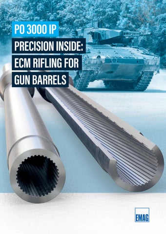
PO 3000 IP PRECISION INSIDE: ECM RIFLING FOR GUN BARRELS
NEW STANDARDS IN PIPE PROCESSING Manufacturing gun barrels places the highest demands on dimensional accuracy, repeatability, and material compatibility. The internal profile with grooves and fields (rifling) in particular requires a precisely defined geometry over the entire length of the barrel—even with tempered or difficultto-machine materials. Conventional processes are reaching their limits here, which is why new, more reliable manufacturing methods are needed. With its electrochemical machining principle, the PO 3000 IP from EMAG ECM sets new standards for the rifling of gun barrels. The machine enables contact-free, stress-free internal machining with exact reproducibility— ideal for calibers up to 63 mm and barrel lengths up to 9,000 mm.
2
Inner Diameter Outer Diameter (optionally extendable)
Component length
Processable calibers (Typical applications in areas such as air defense, small and medium calibers)
PO 3000 IP mm
20–63 (ooptional up to 160)
mm
up to approx. 121
mm
1,000–3,000 (optionally expandable up to 9,000)
mm
20–50
in
in
in
in
0.8–2.5 (optional up to 6.30) up to approx. 4.76
39.4–118.1 (optionally expandable up to 354.3)
0.8–2
PO 3000 IP I New standards in pipe processing
PROCESSING AREA
3
MAIN APPLICATION: RIFLING FOR GUN BARRELS The rifling, i.e., the spiral-shaped internal profile of a gun barrel, gives the projectile a stabilizing rotation as it exits the barrel. This geometry is introduced into the workpiece via the shape of the cathode. The PO 3000 IP enables the economical and highly precise production of these structures.
Gun barrel before ECM rifling
Gun barrel after ECM rifling
ADVANTAGES OF ECM RIFLING: + Machining irrespective of material hardness or structure
+ No influence on the edge zones or mechanical stresses
+ Feasible for complex geometries (e.g., gain twist)
+ No need for straightening processes or thermal posttreatment
ECM rifling is ideal for machining complex internal contours in high-strength materials, such as those used in the defense industry.
4
TECHNOLOGY: ECM – ELECTROCHEMICAL MACHINING
Electrolyte Workpiece = anode
Tool = cathode
Feed
Power source
Voltage U/V
Electrolyte Machining time per workpiece
Udc
Time t/s
PO 3000 IP I Main application: Rifl ing for gun barrels I Technology: ECM – Electrochemical Machining
In the ECM (electrochemical machining) process, material is removed by anodic dissolution of the workpiece in an electrically conductive liquid (electrolyte). The workpiece is the anode, and the tool is a contouring cathode.
KEY FEATURES OF THE ECM PROCESS: Electrolyte flow
» Contactless material removal without mechanical cutting forces » No thermal infl uence on the workpiece
Cathode tool (-)
» No tool wear, as there are no mechanical stresses » Maximum reproducibility thanks to controlled process parameters
Barrel (+)
» Low cathode wear
5
STRUCTURE OF THE PO 3000 IP TECHNICAL DATA
PO 3000 IP
Machining process
Electro Chemical Machining (ECM)
Inner Diameter Outer Diameter (optionally extendable)
Component length
Feed rate
mm
20 – 63 (optional up to 160)
mm
up to approx. 121
mm
1,000 – 3,000 (optionally up to 9,000)
in
0.8 – 2.5 (optional up to 6.30)
in
up to approx. 4.8
in
39.4 – 118.1 (optionally expandable up to 354.3)
mm/min
up to 85
Cycle time (reference)
~35 min at Ø 22 mm / 3,000 mm length
Electrolyte monitoring
Temperature, pressure, flow, pH, Cr⁶+
Workholding technology
Double sleeve with guide rollers
Cathode guide
Non-conductive multipoint guide
Machine design
Portal structure with side loading
1
2
6
COMPARISON WITH CONVENTIONAL METHODS ECM RIFLING (PO 3000 IP)
CLEARING/COLD HAMMERS
Contact-free removal
✔
✖ (high mechanical stresses)
Tool wear
Low cathode wear
High tool wear
Machinable materials
Irrespective of hardness
Limited choice of materials
Post-processing
Not required
Straightening, grinding
Cycle time
~30–60 minutes
~4 hours for the same length
Geometric flexibility
Very high (gain twist, etc.)
Limited
SCALABILITY AND SPECIAL SOLUTIONS The PO 3000 IP is designed for pipes with a length of up to 9 m. Proven concepts are available for larger diameters (> 100 mm) or lengths (> 6 m). In previous projects, systems with a length of up to 24 m (e.g., oil drilling pipes) have already been implemented. This means that the platform can be scaled to specific requirements.
PO 3000 IP I Structure of the PO 3000 IP I Comparison with conventional methods
CRITERION
3
1
Electrical cabinet
2
Cathode
3
Workpiece 7
All EMAG Locations
www.emag.com
Presentation of the machines in trade fair design. 354-1-EN/06.2026· Printed in Germany · © Copyright EMAG · Subject to technical changes.
At Home All Over The World.