


Ball joints are indispensable in our carsas a precise and flexible connection between moving components, where they are used in the stabilizer, steering or suspension, for example. These components are also important in many other industries, such as mechanical engineering.

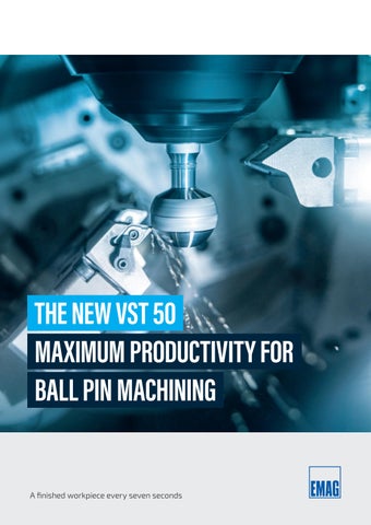
1The components of the joint - such as the ball pin or ball sleeves - are subject to the highest quality requirements and are manufactured with tolerances in the micrometer range. With the new VST 50 machine, EMAG now offers for the first time a machine that has been specially developed for machining the ball and subsequent neck. It ensures extreme leaps in productivity:
» The machine's chip-to-chip time is less than 2 seconds.

» With the help of rapid automation (including three robots), a component leaves the machine approximately every seven seconds.


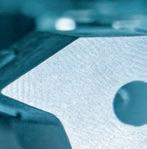
» Focus on high-precision surfaces: The new VST 50 from EMAG ensures high-speed machining of ball pins.

» This means that the machining process on the ball pin is around twice as fast as with other production solutions.
It is important to note that the VST 50 is suitable for both short ball pins (ball diameter 16 to 40 mm, component length 50 to 150 mm) and long ball pins up to 450 mm.


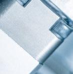
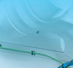
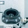
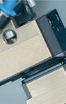
» The VST 50 machines the area marked in green here - i.e. the ball and neck.


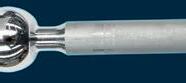

Ball Neck


Spherical surfaces are among the most demanding machining requirements in turning - and EMAG's new machine not only guarantees quality, but also reduces costs per piece. What characterizes the solution in detail?


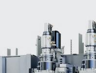

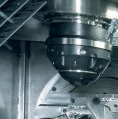
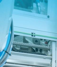
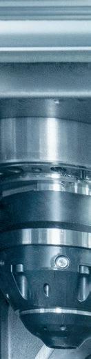
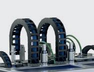
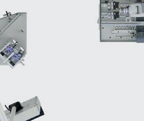
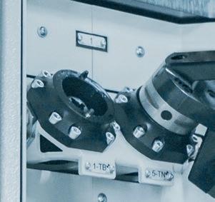
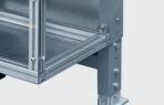
The basic design of the VST 50 includes two workpiece spindles (top) and two tailstocks (bottom).


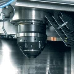
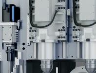
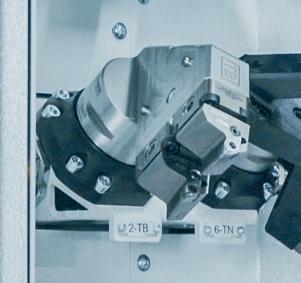
Rotatable B-axis


Tools for turning and rolling the ball
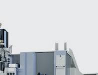
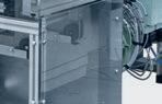
High quality, fast processes, maximum userfriendliness - the designers of the VST 50 had all the factors that stand for economical metal processing in mind. The “technical core” is characterized by a highly stable structure:
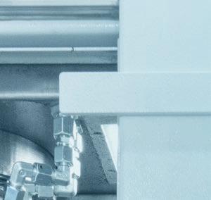
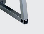
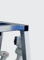
» The basis is a base body made of MINERALIT® polymer concrete, which has eight times better vibration behavior than cast iron. This results in fewer vibrations on the tool, which improves the surfaces during machining.


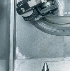
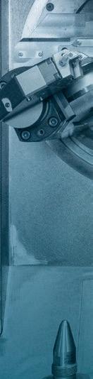
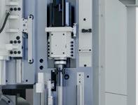
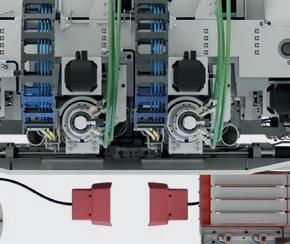
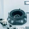
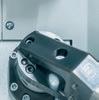
The structure of the compound slides in detail: On the right side are the tools for machining the neck and on the left side are the tools for ball surface. The feed movement for machining the ball is performed by the B-axis. The ball diameter is set by the NC-controlled U-axis.

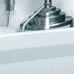
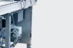
» In the upper area of the work area, there are two suspended workpiece spindles that can be moved irrespective of each other - which means that while one spindle is in use during the machining process, the other can be loaded and unloaded.
» Two tailstocks (in the lower area) can be used as an option - for longer ball pins, for example.
» The “heart” of the machine is located in the middle between the workpiece spindles and tailstocks: the compound slides with the tools.
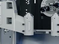
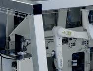
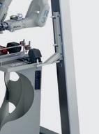
A robot cell is located at the front of the machine for maximum flexibility and speed when loading. The VST 50 can be retooled very quickly. The robots also ensure rapid tool changes, irrespective of the machine operator.


Robot 3:
Parts handling from the transfer station to the outside
Robot 2:
For the right-hand workpiece spindle
Robot 1:
For the left-hand workpiece spindle

Setting master


The tasks of the three robots arranged in parallel are clearly separated from each othereach one takes over a different sub-process in the workpiece flow. Of course, it would be possible to carry out the associated movements with just one robot. However, the desired extremely short cycle times would then not be achieved. The result is a perfectly synchronized interaction at high speed. The overall solution is highly automated:
» The left-hand robot transports the workpieces from the transfer station to the left-hand workpiece spindle (there and back).
» The middle robot transports the workpieces from the transfer station to the right-hand workpiece spindle (there and back).
» The right-hand robot transports the workpieces from the transfer station to the external automation.


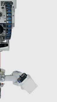


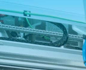
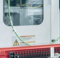
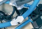
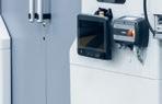
» View of the robot loading of the VST 50: While R1 and R2 load and unload the machine, R3 takes care of the transport between the loading station and the outer conveyor belt in the back ground.


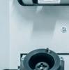
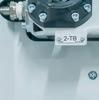
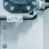


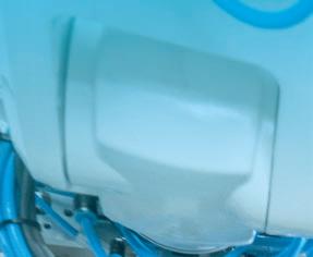
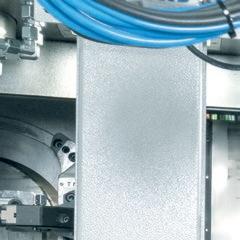
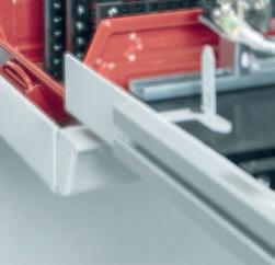
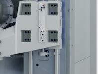
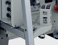
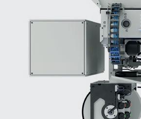
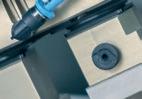
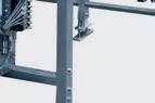
View of the access to the tool magazine on the lefthand side of the machine.


If the operator wants to replace a worn tool, he simply presses a button and the tool magazine swivels outwards for the replacement. Important: The production process is not interrupted during this process!
Once the tool life has expired, the robot changes the two tools.
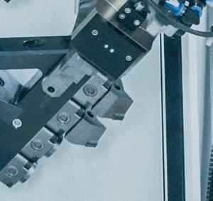
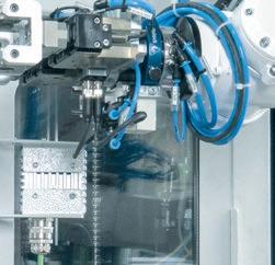
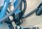
» The robots not only load and unload the machine (pictured here), but also change the tools.

How can you imagine this entire process in detail? The operator loads the tool magazine outside the machine. The magazine is then swung into the work area and the machine carries out the tool changes independently. Once all the tools have been used, the magazine can be swung out again and the operator can replace the tools.
To avoid operating errors, the operator is supported by colored status lights and coded tool receptors.
Minimal downtimes thanks to automatic tool change:
» At the start of the tool change, the robot swaps its workpiece gripper for a tool gripper
» The robot then removes the worn tools from the tool receptors in the work area and places them in the magazine. The new tools are then removed from the magazine and inserted into the tool receptors.
» Tool data can be read and written via an RFID chip before and after machining.


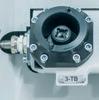
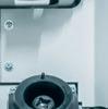
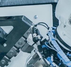
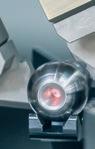
How can high process reliability be guaranteed in demanding machining processes? The answer from EMAG is comprehensive: process cameras and a special light-band micrometer ensure, among other things, consistent component quality and stable production.


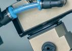
» Camera image of the machine room on the panel: The operator can check here, for example, whether the chip formation is causing a fault in the process.
The machining of the workpiece can be displayed on the control panel using a highresolution camera. This makes it easier for the operator to monitor the process.


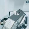
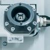
The light-band micrometer determines the required measured values in fractions of a second, whereby the result is very comprehensive: the final ball and neck diameter are determined and any chips are detected at the same time.
Interestingly, all (!) finished components undergo this measurement. Faulty components are automatically rejected.


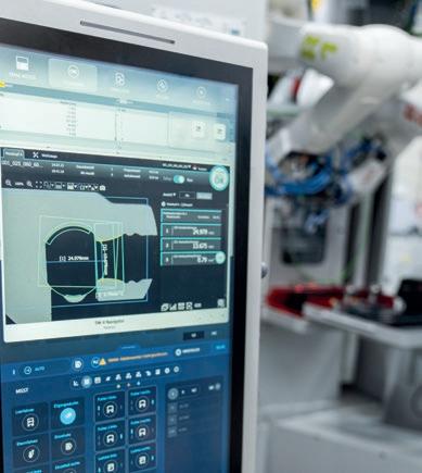
» Comprehensive result:
The recording of the light-band micrometer shows various measured values (see below right).


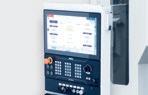


The performance and fl exibility of a CNC machine tool play a decisive role in the ever faster pace of technological development. T he control system, the heart of the machine, has proven to be a key factor for efficient and high-quality production. A current example of this technological progress is the use of the latest control generation SINUMERIK ONE


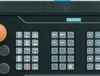


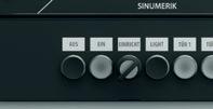

THE ADVANTAGES OF THE SINUMERIK ONE
» Higher performance and efficiency
» Compatibility with previous control systems
» Consistent operation for easy changeover
» Spare parts availability and software updates