Instant digital products (PDF, ePub, MOBI) ready for you
Download now and discover formats that fit your needs...
Visualization, modeling, and graphics for engineering design (non MindTap drafting product; chapters 15-20 not included) Second Edition. Edition Sheryl A. Sorby
Section One: Laying the Foundation Chapter 1 an introduction to graphical communication in engineering 1-2
1.02.01 Ancient History
1.02.02 The Medieval Period
1.02.03 The Renaissance
1.02.04 The Industrial Revolution
1.02.05 More Recent History
1.03.01 Early Years
1.03.02 Instrument Drawing
1.03.03 The Computer Revolution
1.03.04 Graphics as a Design Tool
1.03.05 Graphics as an Analysis Tool 1.03.06 Graphics as a Presentation Tool 1.04 The Modern
2.08.01
3.08.02
3.08.03
4.03.05
4.04.01 Stage 1: Problem Identification
4.04.02 Stage 2: Concept Generation
4.04.03 Stage 3: Concept Selection and Refinement
4.04.04 Stage 4: Design Evaluation and Analysis
4.04.05 Stage 5: Physical Prototyping
4.04.06 Stage 6: Design Documentation
4.04.07 Stage 7: Production
5.02.01 Two-Dimensional CAD
5.02.02 Wireframe Modeling
5.02.03 Surface Modeling
5.02.04
5.03.01 Valid Profiles
5.04.01 Orientation of the Sketch
5.04.02 Geometric Constraints
5.04.03 Dimensional Constraints
5.04.04 Uniqueness of Constraints
5.04.05 Associative and Algebraic Constraints
5.05
5.07.01 The Base Feature
5.07.02 Chamfers, Rounds, and Fillets
5.07.03 Holes
5.07.04 Shells
5.07.05 Ribs and Webs
5.07.06 Other Feature Types
5.07.07 Cosmetic Features
5.07.08 An
5.08.01 Defining Datum Points
5.08.02 Defining Datum Axes
5.08.03 Defining Datum Planes
5.08.04 Chaining Datums
5.08.05 Using Arrays (Rectangular and Circular)
5.08.06 Using Mirrored Features
5.08.07 Using Blends
5.08.08 Sweeps
6.02.01
6.04.01 Concentric Constraints
6.04.02 Mating Surfaces Constraints
6.04.03 Coincident Constraints
6.04.04 Distance Constraints 6.04.05 Adding Constraints to Your Assembly
6.08.01
6.08.02
Metrology Tools for Reverse Engineering
7.03.01 Handheld Calipers
7.03.02 Coordinate Measuring Machine (CMM)
7.03.03 3-D Laser Scanner
7.04 The Reverse Engineering Process 7-5
7.04.01 Defining the Reverse Engineering Project
7.04.02 Dissecting a System
7.04.03 Obtaining Part Sizes
7.04.04 Developing a 3-D CAD Model
7.04.05 Considering Potential Redesign
Geometric Properties Analysis
7.05.01 Measurement Analysis
Mass Properties Analysis 7.06 Finite Element Analysis
7.06.01 Classes of FEA Problems
7.06.02 Finite Element Meshes
7.06.03 Finite Element Boundary Conditions
7.06.04 Finite Element Output
S ECT i O n Three: S ETT ing U P an Engin EE ring d rawing Chapter 8 Orthogonal Projection and Multiview representation 8-2 8.01 Introduction 8-3 8.02 A More Precise Way to Communicate Your Ideas 8-3
8.02.01 Problems with Pictorials
8.02.02 Viewing Planes
8.02.03 Orthogonal Projection
8.02.04 A Distorted Reality
8.02.05 Choice of Viewing Planes
8.02.06 Size and Alignment 8.03 The Glass Box
8.03.01 Standard Views
8.03.02 The Preferred Configuration
8.04 The Necessary Details 8-14
8.04.01 Hidden Lines and Centerlines
8.04.02 The Necessary Views
8.04.03 Hidden Lines versus More Views
8.05 First-Angle Projection versus Third-Angle Projection 8-20
8.06 Breaking the Rules—and Why It Is Good to Break Them Sometimes 8-23
8.06.01 Threaded Parts
8.06.02 Features with Small Radii
8.06.03 Small Cutouts on Curved Surfaces
8.06.04 Small Intersections with Curved Surfaces
8.06.05 Symmetrical Features
8.06.06 Representation of Welds
8.07 When Six Views Are Not Enough 8-28
8.07.01 Features at Odd Angles
8.07.02 Internal Features
8.08 Considerations for 3-D Modeling 8-30
8.09 Chapter Summary 8-31
8.10 Glossary of Key Terms 8-31
8.11 Questions for Review 8-31
8.12 Problems 8-32
9.03.01 Isometric Drawings
9.03.02 Inclined Surfaces
9.03.03 Oblique Surfaces
9.03.04 Cylindrical Surfaces
9.03.05 Ellipses on Inclined Surfaces
9.04 Oblique Drawings 9-16
9.04.01 Types of Oblique Drawings
9.04.02 Construction of Oblique Drawings
9.04.03 Construction of an Object with Circular Features
9.05 Perspective Drawings 9-19
9.05.01 Types of Perspective Drawings
9.05.02 Two-Point Perspective Drawings
9.05.03 Construction of a Two-Point Perspective Drawing
9.05.04 Complex Object in Two-Point Perspective
9.06 Considerations for 3-D Modeling 9-26
9.07 Chapter Summary 9-26
9.08 Glossary of Key Terms 9-27
9.09 Questions for Review 9-27
9.10 Problems 9-28
12.06.01 Different Ways of Specifying the Same Geometry
12.06.02 Identifying and Specifying the Critical Dimensions for Part Function
12.06.03 Baseline versus Chain Dimensioning
12.06.04 What Types of Dimensions Can Be Measured and Checked?
12.07.01 Solid Lines Only
Placement and Spacing
12.08.01 Diameters and Radii
12.08.02 Chamfers
12.08.03 Standard Machined Holes: Countersinks and Counterbores
12.08.04 Slots
13.04.03 English Fits
13.04.04 Metric Fits
13.04.05 Fits Tables 13.05 Conventional Tolerancing versus Geometric Tolerancing 13-15
13.05.01 Features With and Without Size
13.05.02 Conventional Tolerancing and Form
13.05.03 Location of Holes and Pins with Conventional Tolerancing
13.06 Geometric Dimensioning and Tolerancing (GD&T) 13-21
13.06.01 The Datum Reference Frame
13.06.02 Geometry Characteristic Symbols and Feature Control Frames
13.06.03 Order of Precedence for Datums
13.06.04 Position Tolerances versus Conventional Tolerances
14.07.01 Why Construction Drawings Are Different from Manufacturing Drawings
14.07.02 How Construction Drawings Are Different from Manufacturing Drawings
Construction Plans 14-45
14.08.01 Cover Sheet
14.08.02 Site Plan
14.08.03 Elevation Views
14.08.04 Foundation and Floor Plans
14.08.05 Sections
14.08.06 Detail Construction Drawings
14.08.07 Plan and Profile Drawings
14.09 Engineering Scales
14.09.01 Engineer’s Scale
14.09.02 Metric Scale
14.09.03 Architect’s Scale
Chapter 15 working in a Team Environment
15.01 Introduction
15.02 Why Work in a Group?
15.03 What Does It Mean to Be a Team Player?
15.04 Differences between Teaming in the Classroom and Teaming in the Real World
15.05 Team Roles
15.06 Characteristics of an Effective Team
15.06.01 Decisions Made by Consensus
15.06.02 Everyone Participates
15.06.03 Professional Meetings
15.07 Project Organization—Defining Tasks and Deliverables
15.08 Time Management—Project Scheduling
15.08.01 Gantt Charts
15.08.02 Critical Path Method
15.09 Communication
15.09.01 Agreeing How to Communicate
15.09.02 Communicating Outside Meetings
15.09.03 Communicating with the Outside World
15.10 Tools for Dealing with Personnel Issues
15.10.01 Team Contract
15.10.02 Publication of the Rules
15.10.03 Signature Sheet and Task Credit Matrix
15.11 Chapter Summary
15.12 Glossary of Key Terms
Chapter 16 fabrication Processes
16.01 Introduction
16.02 Making Sure It Can Be Made
16.03 Processes for Low-Volume Production
16.03.01 Standard Commercial Shapes
16.03.02 Sawing
16.03.03 Turning
16.03.04 Drilling
16.03.05 Milling
16.03.06 Electric Discharge Machining
16.03.07 Broaching
16.03.08 Rapid Prototyping
16.03.09 Welding and Brazing
16.03.10 Grinding
16.04 Processes for Higher-Volume Production
16.04.01 Sand Casting
16.04.02 Extrusion
16.04.03 Drawing
16.04.04 Rolling
16.04.05 Die Casting and Molding
16.04.06 Forging
16.04.07 Stamping
16.04.08 Sintering
16.05 Burr Removal
16.06 Combined Processes
16.06.01 Example 1: The Retainer
16.06.02 Example 2: The Coupling
16.06.03 Example 3: The Motor Plate
16.07 Considerations for 3-D Modeling
16.08 Chapter Summary
16.09 Glossary of Key Terms
Chapter 17 advanced Visualization Techniques
17.01 Introduction
17.02 Basic Concepts and Terminology in Visualization
17.03 The Possibilities for a Feature Representation
17.04 Other Viewpoints
17.05 Advanced Visualization Techniques
17.05.01 Visualization with Basic Concepts
17.05.02 Strategy for a Holistic Approach to Constructing Pictorials from Multiview Drawings
17.05.03 Strategy for Constructing Pictorials by Inverse Tracking of Edges and Vertices
17.05.04 Strategy for Constructing Pictorials by Inverse Tracking of Surfaces
17.05.05 Strategy for Improving Spatial Skills through Imagining Successive Cuts to Objects
17.06 Chapter Summary
17.07 Glossary of Key Terms
Chapter 18 fasteners
18.01 Introduction
18.02 Screw Threads
18.02.01 Thread Terminology
18.02.02 Single and Multiple Threads
18.02.03 Right- and Left-Hand Threads
18.02.04 Thread Standards
18.02.05 Thread Forms
18.03 Thread Cutting
18.04 Modeling Screw Threads
18.04.01 Thread Representations for Drawings
18.04.02 Thread Representation in Solid Models
18.05 Thread Notes
18.05.01 Metric Threads
18.05.02 Unified National Threads
18.05.03 Other Thread Forms
18.05.04 Thread Notes on a Drawing
18.06 Threaded Fasteners
18.06.01 Bolts and Nuts
18.06.02 Machine Screws and Cap Screws
18.06.03 Studs
18.06.04 Design Considerations for Threaded Fasteners
18.06.05 Set Screws
18.06.06 Self-Tapping Screws
18.07 Rivets
18.07.01 Kinds of Rivets
18.08 Washers
18.09 Pins
18.10 Retaining Rings
18.11 Keys
18.12 Snap-Fit Fasteners
18.13 Chapter Summary
18.14 Glossary of Key Terms
Chapter 19 Technical and Engineering animation
19.01 Introduction
19.02 Animation Process and Technique
19.02.01 The Planning Stage
19.02.02 The Modeling Stage
19.02.03 The Scene Development Stage: Cameras, Lighting, and Rendering
19.02.04 The Animation Stage: Motion and Action
19.02.05 The Output Stage: Editing and Production
19.03 Chapter Summary
19.04 Glossary of Key Terms
Chapter 20 Presentation of Engineering data
20.01 Introduction
20.02 Anatomy of the Information Graphic 20.03 Formats for Quantitative Data
20.03.01 Bar Charts
20.03.02 Line Charts
20.03.03 Pie Charts
20.03.04 Scatter Plots
20.03.05 Tables
20.04 Diagrams
20.04.01 Business Diagrams
20.04.02 Technical Diagrams
20.04.03 Visual Storytelling Diagrams
20.05 Chapter Summary
20.06 Glossary of Key Terms
preface
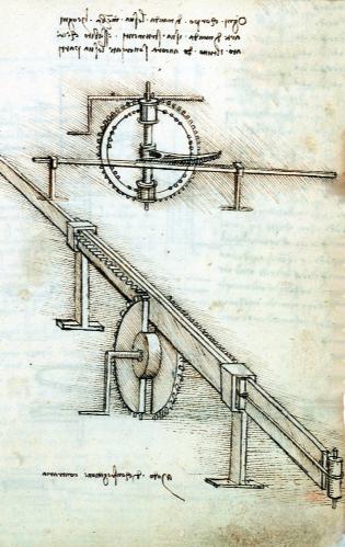
Leonardo da Vinci. You have probably learned that he was a famous Italian artist during the Renaissance. You may even subscribe to some of the conspiracy theories about him that have surfaced recently regarding secret codes and societies. What you may not know about him is that he was one of the very first engineers. (In fact, many people consider him to be the first engineer.) Some even say he was really an engineer who sometimes sold a painting in order to put food on the table. Artists played a prominent role at the birth of modern-day engineering, and some of the first artist-engineers included Francesco di Giorgio, Georg Agricola, and Mariano Taccola. These were the individuals who could visualize new devices that advanced the human condition. Their creativity and willingness to try seemingly “crazy” ideas
propelled technology forward at a much faster pace than had occurred in the previous thousand years.
This marriage between art and engineering has diminished somewhat since the early beginnings of the profession; however, creativity in engineering is still of paramount importance. Would the Apollo spaceship have landed on the moon without the creative thinking of hundreds of engineers who designed and tested the various systems necessary for space travel? Would we be able to instantaneously retrieve information and communicate with one another via the World Wide Web without the vision of the engineers and scientists who turned a crazy idea into reality? Would the modern-day devices that enrich and simplify our lives such as washing machines, televisions, telephones, and automobiles exist without the analytical skills of the engineers and technologists who developed and made successive improvements to these devices? The answer to all of these questions is “no.” The ability to think of systems that never were and to design devices to meet the changing needs of the human population is the purview of the engineering profession.
graphical forms of communication convey design ideas more effectively than do written words. Maybe a picture really is worth a thousand words. As you might expect, the face of engineering graphics has evolved dramatically since the time of da Vinci. Traditional engineering graphics focused on two-dimensional graphical mathematics, drawing, and design; knowledge of graphics was considered a key skill for engineers. Early engineering programs included graphics as an integral topic of instruction, and hand-drawn engineering graphics from 50 years ago are works of art in their own right.
Graphical communication has always played a central role in engineering, perhaps due to engineering’s genesis within the arts or perhaps because
However, in the recent past, the ability to create a 2-D engineering drawing by hand has become de-emphasized due to improvements and advances in computer hardware and software. More recently, as computer-based tools have advanced even further, the demand for skills in 3-D geometric modeling, assembly modeling, animation, and data management has defined a new
Source: NASA/JPL/Cornell University
engineering graphics curriculum. Moreover, three-dimensional geometric models have become the foundation for advanced numerical analysis methods, including kinematic analysis, kinetic analysis, and finite element methods for stress, fluid, magnetic, and thermal systems.
The engineering graphics curriculum has also evolved over time to include a focus on developing 3-D spatial visualization ability since this particular skill has been documented as important to the success of engineers in the classroom and in the field. Spatial visualization is also strongly linked to the creative process. Would da Vinci have imagined his various flying machines without well-honed visualization skills?
We have come full circle in engineering education through the inclusion of topics such as creativity, teamwork, and design in the modern-day graphics curriculum. The strong link between creativity, design, and graphics cannot be overstated. Gone is the need for engineers and technicians who robotically reproduce drawings with little thought involved. With modern-day computational tools, we can devise creative solutions to problems without concern about whether a line should be lightly penciled in or drawn thickly and displayed prominently on the page.
It is for this new, back-to-the-future graphics curriculum that Visualization, Modeling, and Graphics for Engineering Design, Second Edition has been designed. This text is a mixture of traditional as well as modern-day topics, a mixture of analytical and creative thinking, a mixture of exacting drawing technique and freeform sketching. Enjoy.
Development of the Text
Many of the current graphics textbooks were written several years ago with modern-day topics such as
feature-based solid modeling included as a separate add-on to the existing material. In these texts, modern-day computer-based techniques are more of an afterthought: “Oh, by the way, you can also use the computer to help you accomplish some of these common tasks.” In fact, some of the more popular texts were written nearly a century ago when computer workstations and CAD software were figments of some forward-looking engineer’s imagination. Texts from that era focused on drawing technique and not on graphic communication within the larger context of engineering design and creativity.
Modern engineering graphics curricula—and texts—must follow what is happening in the field. Modern product development techniques allow engineers to use computer hardware and software to examine the proper fit and function of a device. Engineers can “virtually” develop and test a device before producing an actual physical model, which greatly increases the speed and efficiency of the design process. The virtual, computer-based model then facilitates the creation of the engineering drawings used in manufacturing and production—an activity that required many hours of hand drafting just a few short decades ago.
In the real world, modern CAD practices have also allowed us more time to focus on other important aspects of the engineering design cycle, including creative thinking, product ideation, and advanced analysis techniques. Some might argue that these aspects are, in fact, the most important aspects of the design process. The engineering graphics curricula at many colleges and universities have evolved to reflect this shift in the design process. However, most engineering graphics textbooks have simply added CAD sections to cover the new topics. Thick textbooks have gotten even thicker. As a wise person has said, “Engineering faculty
are really good at addition, but are miserable at subtraction.”
When we sat down to plan this text, we wanted to produce the engineering graphics benchmark of the future—an engineering graphics approach that teaches design and design communication rather than a vocational text focused on drafting techniques and standards. We wanted to integrate modern-day design techniques throughout the text, not treat these topics as an afterthought.
A strength of this textbook is its focus not only on “what” to do, but also on “why” you do it (or do not do it) that way—concepts as well as details. This text is intended to be a learning aid as well as a reference book. Step-by-step software-specific tutorials, which are too focused on techniques, are very poor training for students who need to understand the modeling strategies rather than just which buttons to push for a particular task. In fact, we believe that mere training should be abandoned in favor of an education in the fundamentals. Students need to learn CAD strategy as well as technique. Students need to develop their creative skills and not have these skills stifled through a focus on the minutiae. In order to prepare for a lifelong career in this fast-changing technological world, students will need to understand fundamental concepts. For example, in the current methodsbased approach to graphics training, students learn about geometric dimensioning and tolerancing. Many texts describe what the symbols mean, but do not explain how, why, and when they should be used. Yet, these questions of how, why, and when are the questions with which most young engineers struggle and the questions that are directly addressed in this text. They are also the important questions—if a student knows the answer to these questions, she or he will understand the fundamental concepts in geometric dimensioning and tolerancing. This fundamental understanding will serve
far into the future where techniques, and possibly the symbols themselves, are likely to change.
Organization of the Text
The textbook is organized into 14 main chapters; a number of supplementary chapters are available in our MindTap product to create custom versions for specific course needs. In organizing the chapters of this text, we were careful to group topics in a way that reflects the modern engineering design process. We purposely did not mimic the decades-old graphics classical texts, which were written in an era when the design process was based on drawings and not computer models, an era when physical and not virtual models were analyzed for structural integrity. For this reason, the order of topics in this text will not match that of the traditional graphics texts where Lettering was often the first topic of instruction.
In this text, we start with foundational topics such as sketching and visualization since these are useful in the initial or “brainstorming” step in the design process and since these are fundamental topics on which many other topics hinge. Also included is a chapter on creativity and design. From there, we move to 3-D modeling because, in the real world, design typically begins with the production of a computer model. In the next stage of the modern design process, a computer model is analyzed either virtually or sometimes physically, and these topics are covered next. Once your model is complete and thoroughly analyzed, engineers move into the design documentation stage where drawings are created and annotated. The text is organized into four major sections as described subsequently. Supplemental chapters cover topics in traditional graphics instruction as well as some modern-day, “not quite ready for primetime” topics such as HTML and web utilization.
Section One—Laying the Foundation
The materials presented here focus on the needs of today’s first-year engineering students who might have well-developed math and computer skills and less-developed hands-on mechanical skills. Incoming engineering students likely no longer work on their cars or bikes in the garage or may not have taken shop and drafting classes in high school. Hands-on tinkering is probably an activity of the past replaced by hands-on web page design and text messaging. (Engineering students of today in all probability have much greater dexterity in their thumbs from “texting” than do the authors of this text!)
Although many engineering students enter college having spent time in a virtual computer environment, the lack of hands-on experiences that involve more than just the thumbs and that also involve real-life physical objects, often results in poorly developed three-dimensional visualization skills. In this section, these skills are explored and developed. This section also includes a project-oriented approach with inclusion of topics in design and creativity to prepare students for a lifetime of professional engineering practice.
Section Two—Modern Design Practice and Tools
The modern topics found in this section reflect the current state of design in industry. Solid modeling has revolutionized engineering graphics. The widespread availability of computers has made three-dimensional modeling the preferred tool for engineering design in nearly all disciplines. Solid modeling allows engineers to easily create mathematical models, parts, and assemblies, visualize and manipulate these models in real time, calculate physical properties, and inspect how they mate with other parts. The modern-day design process is characterized by computer
methods that take advantage of the efficiency and advantages offered by workstations and feature-based modeling software. These new technologies have revolutionized the design process and have enabled around-the-clock engineering. By this model, engineers in Europe hand off (via the Internet) a design project when they leave work to American engineers. The Americans, in turn, hand off the design as they leave the office at the end of the day to Asian engineers. The Asian engineers complete the cycle by passing the design back to the Europeans at the end of their day. The sun never sets on an engineering design. Over your lifelong engineering career, the details of the design process may change again in ways that are unimagined today, but the fundamentals, as described in this section, will migrate from system to system with each advance in technology.
Section Three—Setting up an engineering Drawing
This section contains material found in most conventional textbooks on engineering graphics; however, the content is presented in novel ways and with a fresh approach to problem solving. The topics and techniques in this section are in wide use in engineering graphics classrooms today and are likely to continue to be invaluable into the foreseeable future. These traditional graphics topics continue to be important for several reasons. First, many legacy designs out there were produced prior to the feature-based solid modeling revolution. You may be asked to examine these designs, so it is important that you thoroughly understand drawings. Second, not every company has the capability to go directly from a computer model to a manufactured part, and drawings are still important in these environments. Finally, while the computer can usually automatically generate a drawing for you, certain conventions and dimensioning practices do not translate well. You will need to be
able to verify the integrity of drawings that the computer generates for you and make changes where needed. For all of these reasons, no matter how sophisticated the computer design, hardware and software, or the manufacturing system, engineers must still be able to visualize a three-dimensional object from a set of two-dimensional drawings and vice versa.
Section Four—Drawing Annotation and Design Implementation
The ultimate goal of the engineering design process is to develop devices where everything fits together and functions properly. The sizes of the features that define an object are crucial to the overall functionality of the system. The chapters in this section describe how sizes and geometries of entities are specified. Since no part can be made to an “exact” size even with the best in computer technologies, the allowable errors for part sizes are also described in this section. The final drawings produced in preparation for fabrication must meet exacting criteria to ensure that they are properly cataloged and interpreted for clear communication among all parties. If your drawing includes nonstandard annotations, the machinist or contractor who uses those drawings to produce an engineered system may unknowingly misinterpret the drawing, resulting in higher project costs or even failure. The chapters in this section detail standard practice in drawing annotation to help you avoid making blunders. The ability to make proper, 100 percent correct drawing annotations will likely take you several years to develop. Be patient and keep learning.
Advanced Topics in engineering Graphics
Additional chapters on topics in graphic communication are available in our MindTap product. A chapter is
included to assist you with communicating your thoughts, ideas, analyses, and conclusions through animation, graphs, and charts. You may think that this type of communication is a “no brainer” with modern tools such as a spreadsheet. However, many times the automatically generated graph from a spreadsheet does not follow standard engineering practice for graphic communication and must be edited in order to meet these standards. For example, spreadsheets typically leave axis labels and titles off a graph resulting in a pretty, but meaningless, picture. A picture may be worth a thousand words, but sometimes it takes a few words to describe what a picture is illustrating. For communication with nontechnical (or sometimes even technical) audiences, tremendous amounts of information can be conveyed through the use of animation. If a picture is worth a thousand words, then an animation is surely worth a million.
Chapter Structure
With a few exceptions, each chapter is organized along similar lines. The material is presented with the following outline:
1. Objectives
Chapter-opening objectives alert students to the chapter’s fundamental concepts.
2. Introduction
This section provides an overview of the material that will be presented in the chapter, and discusses why it is important.
3. The Problem
Each chapter directly addresses a certain need or problem in graphical communication. That problem is presented here as if the student had to face such a problem in the field. The presence of a real problem that needs to be solved gives a student added incentive to learn the material in the chapter to solve that problem.
4. Explanation and Justification of Methods
Engineering graphics has evolved and continues to evolve at an increasingly fast pace due to advances in computer hardware and software. Although new methods associated with new technologies exist, these modern methods must remain compatible with conventional graphics practices. This consistency is required to eliminate possible confusion in the interpretation of drawings, maintain sufficient flexibility to create designs unencumbered by the tools available to document them, and reduce the time and effort required to create the drawings.
5. Summary
This section distills the most important information contained in the chapter.
6. Glossary of Key Terms
Formal definitions of the most important terms or phrases for the chapter are provided. Each term or phrase is highlighted the first time it is used in the chapter.
7. Questions for Review
These questions test the student’s understanding of the chapter’s main concepts.
8. Problems
A variety of problems and exercises help to develop skill and proficiency of the material covered in the chapter.
Key Features of the Presentation
We believe that this text will have a broad appeal to engineering graphics students across a wide spectrum of institutions. The following are key features of the text:
• A focus on learning and fundamental skill development, not only on definitions, tools, and techniques. This approach prepares students to apply the material to unfamiliar
problems and situations rather than simply to regurgitate previously memorized material. In the fast-changing world we live in, an understanding of the fundamentals is a key to further learning and the ability to keep pace with new technologies.
• Formal development of visualization skills as a key element at an early stage of the curriculum. Development of these skills is important for students who have not had the opportunity to be exposed to a large number of engineering models and physical devices. Further, the link between visualization and creativity is strong—tools for success over a lifelong career.
• Use of a problem-based approach. This approach presents the student with real problems at the beginning of each chapter, shows the graphics solutions, and then generalizes the solutions.
• A casual tone and student-friendly approach. It is a proven fact that students learn the material better if they are not fast asleep!
• Several common example threads and a common project that are presented in most chapters. The text shows how the material contained in each chapter was actually applied in the context of product development.
One of the case studies to be presented, for example, is the Hoyt AerotecTM Olympic style recurve target bow. The unique geometry of this bow was brought to prominence after it was part of the equipment package used to win the Gold Medal in target archery at the summer Olympic Games in Sydney, Australia. The design history of the development of this product is traced starting from its ideation as an improvement to all other target bows on the market at that time. As a student moves through the chapters of this book, the progress
of the development of this product will be documented. This product was selected as an example for these reasons:
1. It was a very successful design that accomplished all of the goals set forth by its engineers.
2. It was also a product that is relatively unencumbered by the complexity of mechanisms or electronics, which are not the focus of this book.
3. The design is mature, having made it to the consumer market; this means it offers an opportunity to study some of the nontechnical issues that play an important role in engineering design.
Final remarks
This textbook contains a “core” of material covered in a traditional engineering graphics course and also a number of other chapters on modern graphics techniques. The collected material represents over 50 combined years of personal experience in the learning, application, and teaching of engineering graphics. The result is a text that should appeal to both traditional and contemporary graphics curricula. We, the authors, would like to thank you for considering this text.
Dennis K. Lieu
Professor of Mechanical Engineering University of California, Berkeley
Sheryl Sorby
Professor of Engineering Education The Ohio State University
new to This edition
Chapter 1
• The People and Their Skills (Section 1.03) has been removed from the print edition. It can be found in the MindTap course.
Chapter 2
• Strategies for Simple Pictorial Sketches (Section 2.11) has been
removed from the print edition. It can be found in the MindTap course. Caution (pp. 2-27 through 2-29) has been removed from the print edition. It can be found in the MindTap course.
Chapter 3
• New section added discussing the importance of spatial skills.
• Strategies for Developing 3-D Visualization Skills (Section 3.12) has been removed from the print edition. It can be found in the MindTap course.
• Caution (pp. 3-48 through 3-50) has been removed from the print edition. It can be found in the MindTap course.
Chapter 4
• Formerly Chapter 5.
• Patents (Section 5.06) has been removed from the print edition. It can be found in the MindTap course.
Chapter 5
• Formerly Chapter 6.
• Strategies for Making a Model (Section 6.11) has been removed from the print edition. It can be found in the MindTap course.
• Caution (pp. 6-71 through 6-78) has been removed from the print edition. It can be found in the MindTap course.
• Problems 5.1 and 5.4 are new.
Chapter 6
• Formerly Chapter 7.
• The vise assembly example has been removed from the book and is located in the MindTap course.
• Caution (pp. 7-30 through 7-31) has been removed from the print edition. It can be found in the MindTap course.
• Problems 6.2 and 6.5 thru 6.14 are new.
Chapter 7
• Formerly Chapter 8.
• The Finite Element Analysis
Process (Section 8.07) has been removed from the print edition. It can be found in the MindTap course.
• All problems are new.
Chapter 8
• Formerly Chapter 10.
• Strategies for Creating Multiviews from Pictorials (Section 10.06) has been removed from the print edition. It can be found in the MindTap course.
• Caution (pp. 10-51 through 10-62) has been removed from the print edition. It can be found in the MindTap course.
• Problems 8.3 and 8.5 through 8.7 are new.
Chapter 9
• Formerly Chapter 12.
• Step-by-step content has been removed from the print edition. It can be found in the MindTap course.
Chapter 10
• Formerly Chapter 13.
• Procedures for the Creation of Section Views (Section 13.08) has been removed from the print edition. It can be found in the MindTap course.
• Caution (pp. 13-44 through 13-51) has been removed from the print edition. It can be found in the MindTap course.
• Problems 10.5 through 10.9 are new.
Chapter 11
• Formerly Chapter 14.
• Caution (pp. 14-13 through 14-14) has been removed from the print
edition. It can be found in the MindTap course.
• Sketching Techniques for Auxiliary Views (Section 14.06) has been removed from the print edition. It can be found in the MindTap course.
• All new problems.
Chapter 12
• Formerly Chapter 15.
• Problems 12.2 and 12.3 are new.
Chapter 13
• Formerly Chapter 16.
• Caution (pp. 16-44 through 16-48) has been removed from the print edition. It can be found in the MindTap course.
• Examples of Specifying Fits and Geometric Tolerances (Section 16.07) has been removed from the print edition. It can be found in the MindTap course.
Chapter 14
• Formerly Chapter 18.
• Caution (pp. 18-57 through 18-70) has been removed from the print edition. It can be found in the MindTap course.
• All new problems.
Online Content
• Former Chapter 4: Working in a Team Environment has been removed from the print edition. It can be found in the MindTap course.
• Former Chapter 9: Fabrication Processes has been removed from the print edition. It can be found in the MindTap course.
• Former Chapter 11: Advanced Visualization Techniques has been removed from the print edition. It can be found in the MindTap course.
• Former Chapter 17: Fasteners has been removed from the print edition. It can be found in the MindTap course.
Contributors
Holly K. Ault, Worcester Polytechnic Institute (Chapters 5 and 18)
Ron Barr, The University of Texas at Austin (Chapters 4 and 7)
Judy Birchman, Purdue University (Chapter 20)
Ted Branoff, North Carolina State University (Chapters 13 and 18)
Frank Croft, The Ohio State University (Chapter 9)
La Verne Abe Harris, Purdue University (Chapter 20)
Kathy Holliday-Darr, Penn State University, Erie (Chapter 11)
Tom Krueger, The University of Texas at Austin (Chapters 4 and 7)
Jim Morgan, Texas A&M University (Chapter 15)
Bill Ross, Purdue University (Chapter 19)
Mary Sadowski, Purdue University (Chapter 20)
Kevin Standiford, Consultant (Supplemental Chapters 2 and 3)
The authors would like to thank the following people for their contributions to the textbook and their support during its development:
George Tekmitchov and Darrin Cooper of Hoyt USA for their assistance and cooperation with the Aerotec case study material; George Kiiskila of U.P. Engineers and Architects for construction drawings; Fritz Meyers for use of his blueprint drawing; Mark Sturges of Autodesk for graphics materials; Rosanne Kramer of Solidworks for graphics materials; Marie Planchard of Solidworks for graphics materials; James DeVoe of Cengage Learning for his support, confidence, persistence, good humor, and patience in seeing this project through to the end. In
addition, the authors are grateful to the following reviewers for their candid comments and criticisms throughout the development of the text:
Tom Bledsaw, iTT
Ted Branoff, North Carolina State University
Patrick Connolly
Purdue University
richard f. devon
Penn State University
Kathy holliday-darr
Penn State University, Erie
Tamara w. Knott
Virginia Tech
Kellen Maicher
Purdue University
Jim Morgan
Texas A&M University
william a. ross
Purdue University
Mary Sadowski
Purdue University
James Shahan
Iowa State University
Michael Stewart
Georgia Tech
about the authors
Dennis
K. Lieu
Professor Dennis K. Lieu was born in 1957 in San Francisco, where he attended the public schools, including Lowell High School. He pursued his higher education at the University of California at Berkeley, where he received his BSME in 1977, MSME in 1978, and D.Eng. in mechanical engineering in 1982. His major field of study was dynamics and control. His graduate work, under the direction of Professor C. D. Mote, Jr., involved the study of skier/ski mechanics and ski binding function. After graduate studies, Dr. Lieu worked as an advisory engineer with IBM in San Jose CA, where he directed the specification, design, and development of mechanisms and components in the head-disk-assemblies of disk files. In 1988, Dr. Lieu joined the Mechanical Engineering faculty at UC Berkeley. His research laboratory is engaged in research on the mechanics of highspeed electromechanical devices and magnetically generated noise and vibration. His laboratory also studies the design of devices to prevent blunt trauma injuries in sports, medical, and law enforcement applications. Professor Lieu teaches courses in Engineering Graphics and Design of Electromechanical Devices. He was the recipient of a National Science Foundation Presidential Young Investigator Award in 1989, the Pi Tau Sigma Award for Excellence in
Teaching in 1990, the Berkeley Distinguished Teaching Award (which is the highest honor for teaching excellence on the UC Berkeley campus) in 1992, and the Distinguished Service Award from the Engineering Design Graphics Division of ASEE in 2015. He is a member of Pi Tau Sigma, Tau Beta Pi, and Phi Beta Kappa. His professional affiliations include ASEE and ASME. Professor Lieu’s hobbies include Taekwondo (in which he holds a 4th degree black belt) and Olympic style archery.
Sheryl Sorby
Professor Sheryl Sorby is not willing to divulge the year in which she was born but will state that she is younger than Dennis Lieu. She pursued her higher education at Michigan Technological University receiving a BS in Civil Engineering in 1982, an MS in Engineering Mechanics in 1985, and a Ph.D. in Mechanical Engineering-Engineering Mechanics in 1991. She was a graduate exchange student to the Eidgenoessiche Technische Hochshule in Zurich, Switzerland, studying advanced courses in solid mechanics and civil engineering. She is currently a Professor of Engineering Education at The Ohio State University and a Professor Emerita of Mechanical Engineering-Engineering Mechanics at Michigan Technological University. Dr. Sorby is the former Associate Dean for Academic Programs and the former Department
Chair of Engineering Fundamentals at Michigan Tech. She has also served as a Program Director in the Division of Undergraduate Education at the National Science Foundation. She served as a Fulbright Scholar to the Dublin Institute of Technology to conduct research in Engineering Education. Her research interests include various topics in engineering education, with emphasis on graphics and visualization. She was the recipient of the Betty Vetter research award through the Women in Engineering Program Advocates Network (WEPAN) for her work in improving the success of women engineering students through the development of a spatial skills course. She received the Sharon Keillor award for outstanding women in engineering education in 2011. She has also received the Engineering Design Graphics Distinguished Service Award, the Distinguished Teaching Award, and the Dow Outstanding New Faculty Award, all from ASEE.
Dr. Sorby currently serves as an Associate Editor for ASEE’s online journal, Advances in Engineering Education. She is a member of the Michigan Tech Council of Alumnae. She has been a leader in developing first-year engineering and the Enterprise program at Michigan Tech and is the author of numerous publications and several textbooks. Dr. Sorby’s hobbies include golf and knitting.
Chapter 1 An Introduction to Graphical Communication in Engineering 12
Chapter 2 Sketching 21
Chapter 3 Visualization 31
Chapter 4 Creativity and the Design Process 41
The materials presented in this section focus on the needs of today’s beginning engineering students, who typically have welldeveloped math and computer skills but lessdeveloped, hands on mechanical skills compared to students of earlier generations. Incoming engineering students may no longer be people who work on their cars or bikes in the garage and who took shop and drafting classes in high school. Although many engineering students enter college having spent time in a virtual computer environment, the lack of hands on experience often results in a lack of three dimensional visualization skills. So in addition to the classical material on standard engineering graphics practices, these
students need to enhance their visualization skills. Prior to the advent of CAD, the graphics classroom featured large tables topped with mechanical drafting machines and drawers full of mechanical drawing instruments. Engineering students and engineers now have additional time to focus on aspects of the engineering design cycle that are more worthy of their talents as engineers. These aspects include creative thinking, product ideation, and advanced analysis techniques to ensure a manufacturable and robust product. Formalization of the design process allows designers to focus their energies on certain areas in the process and gain more meaningful results.
a n i ntroduction to g raphica L c ommunication in e ngineering c hapter
1
After completing this chapter, you should be able to
• Explain and illustrate how engineering graphics is one of the special tools available to an engineer
• Define how engineering visualization, modeling, and graphics are used by engineers in their work
• Provide a short history of how engineering graphics, as a perspective on how it is used today, was used in the past
1.02
1.01 i ntroduction
Because engineering graphics is one of the first skills formally taught to most engineering students, you are probably a new student enrolled in an engineering program. Welcome!
You may be wondering why you are studying this subject and what it will do for you as an engineering student and, soon, as a professional engineer. This chapter will explain what engineering is, how it has progressed over the years, and how graphics is a tool for engineers.
What exactly is engineering? What does an engineer do? The term engineer comes from the Latin ingenerare, which means “to create.” You may be better able to appreciate what an engineer does if you consider that ingenious also is a derivative of ingenerare. The following serves well enough as a formal definition of engineering:
The profession in which knowledge of mathematical and natural sciences, gained by study, experience, and practice is applied with judgment to develop and utilize economically the materials and forces of nature for the benefit of humanity.
A modern and informal definition of engineering is “the art of making things work.” An engineered part or an engineering system does not occur naturally. It is something that has required knowledge, planning, and effort to create.
So where and how does graphics fit in? Engineering graphics has played three roles through its history:
1. Communication
2. Record keeping
3. Analysis
First, engineering graphics has served as a means of communication. It has been used to convey concepts and ideas quickly and accurately from one person to another without the use of words. As more people became involved in the development of products, accurate and efficient communication became increasingly necessary. Second, engineering graphics has served as a means of recording the history of an idea and its development over time. As designs became more complex, it became necessary to record the ideas or features that worked well in a design so they could be repeated in future applications. And third, engineering graphics has served as a tool for analysis to determine critical shapes and sizes, as well as other variables needed in an engineered system.
These three roles are still vital today, more so than in the past, because of the technical complexity required in making modern products. Computers, three dimensional modeling, and graphics software have made it increasingly effective to use engineering graphics as an aid in design, visualization, and optimization.
a Short history
The way things are done today evolved from the way things were done in the past. You can understand the way engineering graphics is used today by examining how it was used in the past. Graphical communications has supported engineering throughout history. The nature of engineering graphics has changed with the development of new graphics tools and techniques.