Pain Medicine at a Glance 1st Edition
Beth B. Hogans
https://ebookmass.com/product/pain-medicine-at-a-glance-1st-editionbeth-b-hogans/
ebookmass.com
Managerial Economics: Economic Tools for Today’s Decision Makers, 6e 6th Edition Paul G. Keat
https://ebookmass.com/product/managerial-economics-economic-tools-fortodays-decision-makers-6e-6th-edition-paul-g-keat/
ebookmass.com
eTextbook 978-0078021510 Chemistry 12th Edition
https://ebookmass.com/product/etextbook-978-0078021510-chemistry-12thedition/
ebookmass.com
Oxford Casebook of Forensic Psychiatry 1st Edition Nigel Eastman
https://ebookmass.com/product/oxford-casebook-of-forensicpsychiatry-1st-edition-nigel-eastman/
ebookmass.com
McGraw Hill SAT 2023 Christopher Black
https://ebookmass.com/product/mcgraw-hill-sat-2023-christopherblack-2/
ebookmass.com
https://ebookmass.com/product/advances-in-infrastructure-financeraghu-dharmapuri-tirumala/
ebookmass.com
Underwater Inspection and Repair for Offshore Structures
Underwater Inspection and Repair for Offshore Structures
John V. Sharp
Cranfield University
Cranfield UK
Gerhard Ersdal
University of Stavanger Stavanger Norway
This edition first published 2021 © 2021 by John Wiley & Sons Ltd
All rights reserved. No part of this publication may be reproduced, stored in a retrieval system, or transmitted, in any form or by any means, electronic, mechanical, photocopying, recording or otherwise, except as permitted by law. Advice on how to obtain permission to reuse material from this title is available at http://www.wiley.com/go/permissions.
The right of John V. Sharp and Gerhard Ersdal to be identified as the authors of this work has been asserted in accordance with law.
Registered Offices
John Wiley & Sons, Inc., 111 River Street, Hoboken, NJ 07030, USA
John Wiley & Sons Ltd, The Atrium, Southern Gate, Chichester,West Sussex, PO19 8SQ, UK
Editorial Office
The Atrium, Southern Gate, Chichester,West Sussex, PO19 8SQ, UK
For details of our global editorial offices, customer services, and more information about Wiley products visit us at www.wiley.com.
Wiley also publishes its books in a variety of electronic formats and by print-on-demand. Some content that appears in standard print versions of this book may not be available in other formats.
Limit of Liability/Disclaimer of Warranty
While the publisher and authors have used their best efforts in preparing this work, they make no representations or warranties with respect to the accuracy or completeness of the contents of this work and specifically disclaim all warranties, including without limitation any implied warranties of merchantability or fitness for a particular purpose. No warranty may be created or extended by sales representatives, written sales materials or promotional statements for this work. The fact that an organization, website, or product is referred to in this work as a citation and/ or potential source of further information does not mean that the publisher and authors endorse the information or services the organization, website, or product may provide or recommendations it may make. This work is sold with the understanding that the publisher is not engaged in rendering professional services. The advice and strategies contained herein may not be suitable for your situation. You should consult with a specialist where appropriate. Further, readers should be aware that websites listed in this work may have changed or disappeared between when this work was written and when it is read. Neither the publisher nor authors shall be liable for any loss of profit or any other commercial damages, including but not limited to special, incidental, consequential, or other damages.
Library of Congress Cataloging-in-Publication Data
Names: Sharp, John V., 1936- author. | Ersdal, Gerhard, 1966– author.
Title: Underwater inspection and repair for offshore structures / John V. Sharp and Gerhard Ersdal.
Description: First edition. | Hoboken, NJ : Wiley, 2021. | Includes bibliographical references and index.
Identifiers: LCCN 2020042682 (print) | LCCN 2020042683 (ebook) | ISBN 9781119633792 (cloth) | ISBN 9781119633822 (adobe pdf) | ISBN 9781119633815 (epub)
Subjects: LCSH: Offshore structures–Inspection. | Offshore structures–Maintenance and repair.
Classification: LCC TC180 .S46 2021 (print) | LCC TC180 (ebook) | DDC 627/.980288–dc23
LC record available at https://lccn.loc.gov/2020042682
LC ebook record available at https://lccn.loc.gov/2020042683
Cover Design: Wiley
Cover Images: Underwater and above water © SEAN GLADWELL /Getty Images, Oil and gas platform with offshore vessel transporting cargo © Danial_Abdullah / Getty Images, U.S. Navy Diver © Stocktrek Images / Getty Images, A diver inspecting airplane parts in the hold of the Japanese aircraft transport, Fujikawa Maru
© A Cotton Photo / Shutterstock, 3d Rendering of a Subsea ROV Inspecting the Seabed © Vismar UK / Shutterstock
Set in 9.5/12.5pt StixTwoText by SPi Global, Pondicherry, India
Contents
Preface xiii
Definitions and abbreviations xv
1 Introduction to Underwater Inspection and Repair 1
1.1 Background 1
1.2 Why Do We Inspect and Repair Structures 3
1.3 Types of Offshore Structures 6
1.3.1 Fixed Steel Structures 6
1.3.2 Floating Structures 8
1.3.3 Concrete Platforms 9
1.4 Overview of this Book 10
1.5 Bibliographic Notes 11 References 11
2 Statutory Requirements for Inspection and Repair of Offshore Structures 13
2.1 Introduction 13
2.2 Examples of Country Statutory Requirements 14
2.2.1 Introduction 14
2.2.2 Regulation in the US Offshore Industry 15
2.2.3 Regulation in the UK Offshore Industry 16
2.2.4 Regulation in the Norwegian Offshore Industry 17
2.3 Standards and Recommended Practices for Steel Structures 17
2.3.1 Introduction 17
2.3.2 API RP-2A and API RP-2SIM (Structural Integrity Management) 18
2.3.3 API RP-2FSIM (Floating Systems Integrity Management) 21
2.3.4 ISO 19902 22
2.3.5 ISO 19901-9 23
2.3.6 NORSOK N-005 23
2.4 Standards and Recommended Practices for Mooring Systems 24
2.4.1 Introduction 24
2.4.2 API RP-2MIM (Mooring Integrity Management) 25
2.4.3 IACS Guideline for Survey of Offshore Moorings 26
2.5 Standards and Guidance Notes for Concrete Structures 27
2.5.1 Introduction 27
2.5.2 ISO 19903— Concrete Structures 27
2.5.3 Department of Energy Guidance Notes 31
2.5.4 NORSOK N-005— Concrete Structures 32
2.6 Discussion and Summary 33 References 34
3 Damage Types in Offshore Structures 37
3.1 Introduction 37
3.1.1 General 37
3.1.2 Corrosion 38
3.1.3 Cracking Due to Fatigue 40
3.1.4 Dents, Bows and Gouges Due to Impact 41
3.1.5 Cracking Due to Hydrogen Embrittlement 42
3.1.6 Erosion, Wear and Tear 42
3.1.7 Brittle Fracture 43
3.1.8 Grout Crushing and Slippage 43
3.2 Previous Studies on Damage to Offshore Structures 43
3.3 Previous Studies on Damage to Fixed Steel Structures 44
3.3.1 MTD Underwater Inspection of Steel Offshore Structures 44
3.3.2 MTD Review of Repairs to Offshore Structures and Pipelines 46
3.3.3 PMB AIM Project for MMS 47
3.3.4 HSE Study on Causes of Damage to Fixed Steel Structures 50
3.3.5 Single-Sided Closure Welds 51
3.3.6 MSL Rationalization and Optimisation of Underwater Inspection Planning Report 52
3.3.7 Studies on Hurricane and Storm Damage 54
3.4 Previous Studies on Damage to Floating Steel Structures 57
3.4.1 D.En. Studies on Semi-Submersibles 57
3.4.2 SSC Review of Damage Types to Ship-Shaped Structures 57
3.4.3 Defect Type for Tanker Structure Components 59
3.4.4 Semi-Submersible Flooding Incident Data 59
3.5 Previous Studies on Damage Types to Mooring Lines and Anchors 61
3.5.1 Introduction and Damage Statistics for Moorings 61
3.5.2 API RP-2MIM Overview of Damage Types to Mooring Lines 62
3.5.3 HSE Studies on Mooring Systems 63
3.5.4 Studies on Corrosion of Mooring Systems 64
3.5.5 Studies on Fatigue of Mooring Systems 64
3.6 Previous Studies on Concrete Structures 66
3.6.1 Concrete in the Oceans Project 66
3.6.2 Durability of Offshore Concrete Structures 67
3.6.3 PSA Study on Damage to Offshore Concrete Structures 68
3.7 Previous Studies on Marine Growth (Marine Fouling) 70
3.8 Summary of Damage and Anomalies to Offshore Structures 72
3.8.1 General 72
3.8.2 Damage Types Specific to Steel Structures 72
3.8.3 Damage Types Specific to Concrete Structures 75
3.8.4 Summary Table of Damage to Different Types of Structures 75
3.9 Bibliographic Notes 76 References 76
4 Inspection Methods for Offshore Structures Underwater 79
4.1 Introduction to Underwater Inspection 79
4.2 Previous Studies on Inspection 81
4.2.1 Introduction 81
4.2.2 SSC Survey of Non-Destructive Test Methods 81
4.2.3 Underwater Inspection / Testing / Monitoring of Offshore Structures 84
4.2.4 HSE Handbook for Underwater Inspectors 85
4.2.5 MTD Underwater Inspection of Steel Offshore Structures 85
4.2.6 Department of Energy Fourth Edition Guidance Notes on Surveys 86
4.2.7 HSE Detection of Damage to Underwater Tubulars and Its Effect on Strength 87
4.2.8 MSL Rationalization and Optimisation of Underwater Inspection Planning Report 89
4.2.9 Projects on Testing of Inspection Methods and Their Reliability 93
4.2.10 Concrete in the Oceans Programme 96
4.3 Inspection and Inspection Methods 100
4.3.1 Introduction 100
4.3.2 Visual Inspection 100
4.3.3 Ultrasonic Testing Methods 103
4.3.4 Electromagnetic Methods 104
4.3.5 Radiographic Testing 106
4.3.6 Flooded Member Detection 106
4.3.7 Rebound Hammer 108
4.3.8 Chloride Ingress Test 108
4.3.9 Electro-Potential Mapping 109
4.3.10 Cathodic Protection Inspection 111
4.4 Deployment Methods 112
4.4.1 Introduction 112
4.4.2 Divers 113
4.4.3 ROV and AUV 114
4.4.4 Splash Zone Access 116
4.4.5 Summary of Inspection Methods and Their Deployment 117
4.5 Competency of Inspection Personnel and Organisations 117
4.5.1 Introduction 117
4.5.2 Regulatory Requirements on Competency 119
4.5.3 Requirements on Competency in Standards 119
4.5.4 Certification and Training of Inspectors 121
4.5.5 Trials to Study Inspector Competency 121
4.5.6 Organisational Competency 122
4.6 Reliability of Different Inspection Methods Underwater 124
4.7 Inspection of Fixed Steel Structures 126
4.8 Inspection of Concrete Structures 128
4.9 Inspection of Floating Structures and Mooring Systems 133 References 137
5 Structural Monitoring Methods 141
5.1 Introduction 141
5.1.1 General 141
5.1.2 Historical Background 142
5.1.3 Requirements for Monitoring in Standards 145
5.2 Previous Studies on Structural Monitoring Methods 146
5.2.1 MTD Underwater Inspection of Steel Offshore Installations 146
5.2.2 HSE Review of Structural Monitoring 146
5.2.3 HSE Updated Review of Structural Monitoring 148
5.2.4 SIMoNET 150
5.3 Structural Monitoring Techniques 151
5.3.1 Introduction 151
5.3.2 Acoustic Emission Technique 151
5.3.3 Leak Detection 152
5.3.4 Global Positioning Systems and Radar 152
5.3.5 Fatigue Gauge 153
5.3.6 Continuous Flooded Member Detection 153
5.3.7 Natural Frequency Monitoring 153
5.3.8 Strain Monitoring 154
5.3.9 Riser and Anchor Chain Monitoring 155
5.3.10 Acoustic Fingerprinting 155
5.3.11 Monitoring with Guided Waves 155
5.4 Structural Monitoring Case Study 155
5.5 Summary on Structural Monitoring 157
5.6 Bibliographic Notes 159 References 159
6 Inspection Planning, Programme and Data Management 161
6.1 Introduction 161
6.1.1 General 161
6.1.2 Long-Term Inspection Plan 162
6.1.3 Approaches for Long-Term Inspection Planning 163
6.1.4 Inspection Programme 167
6.1.5 Integrity Data Management 170
6.1.6 Key Performance Indicators 173
6.2 Previous Studies on Long-Term Planning of Inspections 173
6.2.1 PMB AIM Project for MMS 173
6.2.2 MSL Rationalization and Optimisation of Underwater Inspection Planning Report 174
6.2.3 HSE Study on the Effects of Local Joint Flexibility 175
6.2.4 HSE Ageing Plant Report 176
6.2.5 Studies on Risk-Based and Probabilistic Inspection Planning 176
6.2.6 EI Guide to Risk-Based Inspection Planning 180
6.3 Summary on Inspection Planning and Programme 180
6.3.1 Introduction 180
6.3.2 Fixed Steel Platforms 181
6.3.3 Floating Steel Structures 182
6.3.4 Concrete Platforms 183
6.4 Bibliographic Notes 184 References 184
7 Evaluation of Damage and Assessment of Structures 187
7.1 Introduction 187
7.2 Previous Studies on Evaluation of Damaged Tubulars 189
7.2.1 Remaining Fatigue Life of Cracked Tubular Structures 189
7.2.2 Static Strength of Cracked Tubular Structures 195
7.2.3 Effect of Multiple Member Failure 199
7.2.4 Corroded Tubular Members 201
7.2.5 Dent and Bow Damage to Underwater Tubulars and Their Effect on Strength 205
7.2.6 Studies on Assessment of System Strength 208
7.2.7 PMB AIM Project for MMS 209
7.2.8 MSL Significant JIP for MMS 211
7.2.9 MSL Assessment of Repair Techniques for Ageing or Damaged Structures 214
7.3 Previous Studies on Evaluation of Damaged Plated Structures 215
7.3.1 Introduction 215
7.3.2 SSC Studies on Residual Strength of Damaged Plated Marine Structures 216
7.4 Previous Studies on Evaluation of Damaged Concrete Structures 218
7.4.1 Department of Energy Assessment of Major Damage to the Prestressed Concrete Tower 218
7.4.2 Department of Energy Review of Impact Damage Caused by Dropped Objects 220
7.4.3 HSE Review of Durability of Prestressing Components 220
7.4.4 HSE Review of Major Hazards to Concrete Platforms 220
7.4.5 Department of Energy Review of the Effects of Temperature Gradients 221
7.4.6 Concrete in the Oceans Review of Corrosion Protection of Concrete Structures 221
7.4.7 Norwegian Road Administration Guideline V441 222
7.5 Practice of Evaluation and Assessment of Offshore Structures 223
7.5.1 General 223
7.5.2 Fixed and Floating Steel Structures 225
7.5.3 Concrete Structures 230 References 232
8 Repair and Mitigation of Offshore Structures 239
8.1 Introduction to Underwater Repair 239
8.2 Previous Generic Studies on Repair of Structures 242
8.2.1 UEG Report on Repair to North Sea Offshore Structures 242
8.2.2 MTD Study on Repairs of Offshore Structures 242
8.2.3 UK Department of Energy Fourth Edition Guidance Notes 247
8.2.4 DNV GL Study on Repair Methods for PSA 248
8.3 Previous Studies on Repair of Tubular Structures 250
8.3.1 Grout Repairs to Steel Offshore Structures 250
8.3.2 UK Joint Industry Repairs Research Project 252
8.3.3 UK Department of Energy and TWI Study on Repair Methods for Fixed Offshore Structures 254
8.3.4 UK Department of Energy–Funded Work on Adhesive Repairs 257
8.3.5 Residual and Fatigue Strength of Grout-Filled Damaged Tubular Members 260
8.3.6 Fatigue Life Enhancement of Tubular Joints by Grout Injection 261
8.3.7 ATLSS Projects on Repair to Dent-Damaged Tubular Members 261
8.3.8 ATLSS Projects on Repair to Corrosion Damaged Tubulars 263
8.3.9 MSL Strengthening, Modification and Repair of Offshore Installations 265
8.3.10 MSL Underwater Structural Repairs Using Composite Materials 266
8.3.11 HSE Experience from the Use of Clamps Offshore 267
8.3.12 MSL Study on Neoprene-Lined Clamps 269
8.3.13 MSL Repair Techniques for Ageing and Damaged Structures 270
8.3.14 MMS Studies on Hurricane Damage and Repair 273
8.3.15 BOEME Report on Wet Weld Repairs to US Structures 274
8.4 Previous Studies on Repair of Concrete Structures 276
8.4.1 Introduction 276
8.4.2 Repair of Major Damage to Concrete Offshore Structures 277
8.4.3 Scaling of Underwater Concrete Repairs 278
8.4.4 Assessment of Materials for Repair of Damaged Concrete Underwater 280
8.4.5 Effectiveness of Concrete Repairs 285
8.5 Previous Studies on Repair of Plated Structures 286
8.6 Repair of Steel Structures 289
8.6.1 Introduction 289
8.6.2 Selection of Mitigation and Repair Methods 290
8.6.3 Machining Methods (Grinding) 295
8.6.4 Re-Melting Methods 297
8.6.5 Weld Residual Stress Improvement Methods (Peening) 297
8.6.6 Stop Holes and Crack-Deflecting Holes 298
8.6.7 Structural Modifications 300
8.6.8 Underwater Welding 301
8.6.9 Doubler Plates 305
8.6.10 Removal of Structural Elements 305
8.6.11 Bonded-Type Repairs 306
8.6.12 Structural Clamps and Sleeves 307
8.6.13 Grout Filling of Members 310
8.6.14 Grout Filling of Tubular Joints 312
8.6.15 Installation of New Structural Elements 312
8.6.16 Summary of Steel Repairs 313
8.7 Repair of Corrosion and Corrosion Protection Systems 316
8.7.1 Introduction 316
8.7.2 Repair of Damaged Coatings 318
8.7.3 Replacement of Corroded Material 318
8.7.4 Repair or Replacement of the Corrosion Protection System 318
8.8 Repair of Mooring Systems 319
8.9 Repair of Concrete Structures 320
8.9.1 Introduction 320
8.9.2 Choice of Repair Method 322
8.9.3 Concrete Material Replacement 323
8.9.4 Injection Methods 325
8.9.5 Repair of Reinforcement and Prestressing Tendons 326
8.9.6 Summary of Concrete Repairs 327
8.10 Overview of Other Mitigation Methods 328
8.11 Bibliographic Notes 329 References 329
9 Conclusions and Future Possibilities 337
9.1 Overview of the Book 337
9.2 Emerging Technologies 338
9.3 Final Thoughts 340 References 341
Index 342
Preface
All structures deteriorate and experience damage with time, particularly due to fatigue cracking, corrosion and damage from extreme and accidental events. This requires inspections, monitoring and appropriate repair of these structures to be performed to avoid an unsafe condition. Significant research and development work have been undertaken related to typical damage types, inspection and monitoring methods, evaluation of damage, and the need and methods for repair. This book aims at giving the reader an overview of this research and development work in addition to providing current practice in these areas, both to inform the reader about the existence of this work and to avoid unnecessary repetition of research and development.
Since early 1980 the first author of this book, John V. Sharp, has been active in the majority of these research programmes through his role initially in managing the relevant UK Department of Energy research work and later as Head of Offshore Research for the UK HSE. Since early 2000 the second author, Gerhard Ersdal, has had similar roles in managing several research programmes funded by the Norwegian Petroleum Safety Authority. Both authors have specific relevant expertise and have published a number of papers on inspection and repair of offshore structures and both are now actively involved in these areas at the universities of Cranfield and Stavanger, respectively, as Visiting (part-time) Professors.
The authors have had the benefit of working closely with John Wintle, Visiting Professor at the University of Strathclyde and Consultant Engineer at TWI, in preparing this book and his contributions have made significant improvements to the final text.
This book has mainly been written by using online web-conferencing and in its later stages this has been forced upon us because of the Covid-19 lockdown in the UK, Norway and many other parts of the world.
The opinions expressed in this book are those of the authors, and they should not be construed as reflecting the views of the organisations the authors represent. Further, the text in this book should not be viewed as recommended practice but rather as an overview of important issues that are involved in the management of inspection and repair.
The authors would particularly like to thank Mostafa Atteya, Eirik Duesten and Rolf Hanson for carefully reviewing the document and providing many valuable comments. We also want to thank Mick Else and Fu Wu for their efforts in enabling copyrights for essential illustrations. Further, the authors would like to thank Stinger (stinger.com), OceanTech (oceantech.com), BSEE, KBR Energo, Fugro and Atkins (MSL) for allowing us to use their illustrations and Magnus Gabriel Ersdal for drafting some of the figures and valuable input on artificial intelligence and machine learning. The authors would also like to thank the helpful and patient staff at Wiley.
Microsoft Teams, East Hendred, Oxfordshire and Stavanger, July 2020
John V. Sharp
Gerhard Ersdal
Definitions and abbreviations
Accidental limit state (ALS)
Acoustic emission
Check of the collapse of the structure due to the same reasons as described for the ultimate limit state but exposed to abnormal and accidental loading situations
The production of sound waves by a material when it is subjected to stress
ACFM Alternating Current Frequency Modulated (type of inspection)
ACPD Alternating Current Potential Drop (type of inspection)
Admixture
Ageing
AIM project
Anomaly
As-built documentation
Asset integrity management (AIM)
Barrier
Material added during the mixing process of concrete in small quantities related to the mass of cement to modify the properties of fresh or hardened concrete
Process in which integrity (i.e., safety) of a structure or component changes with time or use
A project undertaken by the US Mineral Management Services (MMS) for assessment, inspection and maintenance, providing guidance on managing the integrity of existing fixed steel platforms in the Gulf of Mexico.
In-service measurement (damage, deterioration, defect, degradation, etc.) that is outside the threshold acceptable from the design or most recent fitness for service assessment
Documentations that includes as-built documentation collected during in-service
AIM is the means of ensuring that the people, systems, processes and resources that deliver integrity are in place, in use and will perform when required over the whole life cycle of the asset
A measure intended to either identify conditions that may lead to failure or hazardous and accidental situations, prevent an actual sequence of events occurring or developing, influence a sequence of events in a deliberate way, or limit damage and/or loss
Bilge The area on the outer surface of a ship’s hull where the bottom shell plating meets the side shell plating
Caisson
Major part of fixed concrete offshore structure, providing buoyancy during floating phases and the possibility of oil storage within the structure, also used for pipework from topside to underwater typically water lift (intake of firewater, cooling water, etc.) and outlet of wastewater
CFRP Carbon Fiber Reinforced Polymer
Definitions and abbreviations
Clamp
Collapse
A fabricated steel construction encompassing an existing tubular member or a nodal joint. A clamp consists of two or more parts that are bolted together. There are a number of clamp variants depending on whether or not the clamp parts are compressed against the existing member/joint and on whether there is a medium (grout or neoprene) placed between the clamp steelwork and the member/joint. A clamp should not be confused with a guide, which can appear to be superficially similar
Total loss of the load bearing capacity of the platform through failure of one or more structural components
CP Cathodic Protection
Curing
CVI
Defect
Design service life
DFI resume
Discontinuity
Duty holder
DVI
EC, ET
Evaluation
Fairlead
False indication
Fatigue limit state (FLS)
Fatigue Utilisation Index (FUI)
FCAW
Fixed structure
Action taken to maintain favourable moisture and temperature conditions of freshly placed concrete or cementitious materials during a defined period of time following placement
Close visual inspection (type of inspection)
An imperfection, fault or flaw in a component
Assumed period for which a structure is to be used for its intended purpose with anticipated maintenance but without substantial repair from ageing processes being necessary
A document summarising key information concerned with the design, fabrication and installation
A lack of continuity or cohesion; an intentional or unintentional interruption in the physical structure or configuration of a material or component
A UK term for the operator in the case of a fixed installation (including fixed production and storage units) and for the owner in the case of a mobile installation
Detailed visual inspection (type of inspection)
Eddy current testing (type of inspection)
The process of evaluating whether identified changes, defects or anomalies need repair, further inspection or a more detailed assessment
A device to guide a mooring line and to stop it moving laterally before it enters the vessel
An indication that is interpreted to be caused by a discontinuity at a location where no discontinuity exists
Check of the cumulative fatigue damage due to repeated loads or the fatigue crack growth capacity of the structure
FUI is the ratio between the effective operational time and the documented fatigue life
Acronym for Fluxed Cored Arc Welding
Structure that is bottom founded and transfers all actions on it to the sea floor
Flaw An imperfection or discontinuity that may be detectable by non-destructive testing
FRP
Fiber Reinforced Polymer
FSU Floating storage units
FSO Floating storage and offloading units
FPSO
Flooded member detection (FMD)
GMAW
Floating production, storage and offloading units
Inspection technique that relies on the detection of water penetrating a member by using radiographic or ultrasonic methods
Gas Metal Arc Welding
Gross errors
Grout
GTAW
GVI
HAZ
Hazard
High Strength Steels (HSS)
Hydrogen induced cracking (HIC) or hydrogen induced stress cracking (HISC)
Inspection programme
Integrity
Integrity management
Jack-ups
JIP
Kenter shackle
KPI
Life extension
Limit state
Management of change (MoC)
Marine fouling (growth)
Metocean
Microbiologically induced cracking (MIC)
MIG
Mitigation
Significant errors, mistakes and omissions in the form of anomaly or defects that may lead to local or global failures
A mixture of cementitious materials and water, with or without aggregate, to fill cavities and components to form a solid mass when set
Gas Tungsten Arc Welding
General visual inspection (type of inspection)
Heat affected zone related to welding
Situations with potential for human injury, damage to the environment, damage to property, or a combination of these
Steels with yield strengths in excess of 500 MPa
The process by which hydride-forming metals such as steel become brittle and fracture due to the introduction and subsequent diffusion of hydrogen into the metal
Scope of work for the offshore execution of the inspection activities to determine the condition and configuration of the structure
The state of the structure, ideally being fit for service, and with an acceptable level of safety against failure
Continuous process to manage all changes that will occur during operational life that may affect the integrity of structures and marine systems
Mobile offshore unit with a buoyant hull and legs that can be moved up and down relative to the hull
Joint Industry Project, usually in research and development
A device for joining two chain links as a repair
Key performance indicator, measurement of performance against targets
The use of structures beyond their originally defined design life
A state beyond which the structure no longer fulfils the relevant design criteria
A recognised process that is required when significant changes are made to an activity or process which can affect performance and risk
Seaweed, bacteria and other living organisms in the seawater typically adhering to immersed surfaces such as offshore structures, which may build up to significant thicknesses
Syllabic abbreviation of meteorology and (physical) oceanography
A form of degradation that can occur as a result of the metabolic activities of bacteria in the environment. The bacteria that cause MIC can accelerate the corrosion process because the conditions that apply already have elements of a corrosion cell
Metal Inert Gas
Limitation of negative consequence or reduction in likelihood of a hazardous event or condition
MMA Manual Metal Arc
MPI
Mudmat
NDE
NDT
Magnetic Particle Inspection (type of inspection)
A structure used to prevent offshore structures from sinking into soft unconsolidated soil on the seabed.
Non-Destructive Examination
Non-Destructive Testing
Node
Non-redundant
Joining point for brace members in a jacket-type structure
Structure that fails when the first primary structural member fails
OPB Out-of-Plane Bending
Partial safety factor (for materials) factor that takes into account unfavourable deviation of strength from the characteristic value and inaccuracies in determining the actual strength of the material
(for loads) factor that takes into account the possible deviation of the actual loads from the characteristic value and inaccuracies in the load determination
Passive fire protection (PFP)
Peening
Performance standards
Pre-stressing tendons
Primary structure
Progressive collapse
Push-over analysis
PWHT
Redundancy
Reserve strength ratio (RSR)
Residual strength
Return period
Risk based inspection
Robustness
Coatings used on critical areas that could be affected by a jet fire. There are several different types, which include cementitious and epoxy intumescent based
Process of working a metal’s surface to improve its material properties, usually by mechanical means
Statement of the performance required of a structure, system, equipment, person or procedure and that is used as the basis for managing the hazard through the life cycle of the platform
High strength tendons required to maintain the structural integrity of a concrete structure, particularly in the towers (shafts). These tendons are placed in steel ducts, which are grouted following tensioning
All main structural components that provide the structure’s main strength and stiffness
The sequence of component failures (from an initial local failure) that will eventually lead to the collapse of an entire structure or large part of it
Non-linear analysis for jacket structures used for determining the collapse / ultimate capacity
Post Weld Heat Treatment
The ability of a structure to find alternative load paths following failure of one or more components, thus limiting the consequences of such failures
The ratio between the design loading (usually 100-year loading) and the collapse / ultimate capacity
Ultimate global strength of an offshore structure in a damaged condition
An engineering simplification representing the probability (q) of an event by an assumed average period between occurrences of an event or of a particular value being exceeded. For q less than 0.1 this corresponds approximately to a return period of 1/q years
Inspection plans developed from an evaluation of the likelihood and consequences of failure associated with a structure to develop the inspection scope and frequency
Measure of the ability of the structure to be damage tolerant and to sustain deviations from the assumptions to which the structure originally was designed
ROV Remotely Operated Vehicle
RT
Safety critical elements (SCE) and Safety and environmental critical elements (SECE)
Radiographic testing (type of inspection)
Systems and components (e.g., hardware, software, procedures) that are designed to prevent, control, mitigate or respond to a major accident event (MAE) that could lead to injury or death. This was further extended in the 2015 version of the UK safety case regulation to include environmental critical elements
SCF Stress Concentration Factor
Scour
Secondary structure
Erosion of the seabed around a fixed structure produced by waves, currents and ice
Structural components that, when removed, do not significantly alter the overall strength and stiffness of the global structure
Serviceability limit state (SLS)
Sleeve
Definitions and abbreviations
A check of functionalities related to normal use (such as deflections and vibrations) in structures and structural components
A sleeve is a concentric tubular surrounding a leg or brace member that is several diameters long. The annular gap between the sleeve and member is normally grouted. In the case of an existing member, the sleeve is necessarily split longitudinally and the two halves are joined during installation using short bolts
SMR Strengthening, Modification and Repair
SMYS
S-N curve
Splash zone
Specified Minimum Yield Stress
A relationship between applied stress range (S) and the number of cycles (N) to fatigue failure (regarding fatigue failure, see fatigue limit state)
Part of a structure close to sea level that is intermittently exposed to air and immersed in the sea
SSC Ship Structures Committee
SPT
Station keeping system
Stress concentration factor (SCF)
Structural integrity
Structural integrity management (SIM)
Structural reliability analysis (SRA)
Stud (chain)
Studbolt
Subsidence
Surveillance
Testing
Sacrificial pre-treatment technique (used in adhesive repair)
System capable of limiting the excursions of a floating structure within prescribed limits
Factor relating a nominal stress to the local structural stress at a detail
A state of being intact and fit for purpose, with an acceptable level of safety against failure
Means of demonstrating that the people, systems, processes and resources that deliver structural integrity are in place, in use and will perform when required of the whole life cycle of the structure
Method used to analyse the probability of limit state failure of structures
Crossbar in the centre of a link of a chain, either welded or mechanically fixed
A threaded rod, generally used in stressed clamps
Settlement of the structure that results, primarily from extraction of reservoir hydrocarbons
All activities performed to gather information required to assure the structural integrity, such as inspection of the condition and configuration, determining the loads, records, and document review (such as standards and regulations)
Testing or examination of a material or component in accordance with a guideline, or a standard, or a specification or a procedure in order to detect, locate, measure and evaluate flaws
TIG Tungsten Inert Gas
Topsides
Ultrasonic testing
Ultimate limit state (ULS)
Vibration monitoring
Watertight integrity
Wave-in-deck
Structures and equipment placed on a supporting structure (fixed or floating) to provide some or all of a platform’s functions
A family of non-destructive testing techniques based on the propagation of ultrasonic waves in the object or material being tested
A check of failure of the structure of one or more of its members due to fracture, rupture, instability, excessive inelastic deformation, etc.
Natural frequency monitoring to measure stiffness
The capability of preventing the passage of water through the structure at a given pressure head
Waves that impact the deck of a structure, which dramatically increase the wave loading on the structure
Introduction to Underwater Inspection and Repair
The way you learn anything is that something fails, and you figure out how not to have it fail again1 .
—Robert S. Arrighi
Repair is an exacting, technical matter involving five basic steps: (1) finding the deterioration, (2) determining the cause, (3) evaluating the strength of the existing structure, (4) evaluating the need for repair and (5) selecting and implementing a repair procedure2 .
—Sidney M. Johnson
Before anything else, preparation is the key to success3 .
1.1 Background
—Alexander Graham Bell
Offshore structures for the production of oil and gas have a long history. The early offshore oil and gas exploration started in the 1940s in the Gulf of Mexico (GoM) and the Caspian Sea4. This was followed by the development of the North Sea and Brazil in the 1960s and later activities in the Persian Gulf, Africa, Australia, Asia and other areas. More recently offshore structures for wind energy production have been developed, initially in Denmark in the early 1990s followed by significant growth in several European countries, particularly the UK.
1 Source: Robert S. Arrighi, “Pursuit of Power: NASA’s Propulsion Systems Laboratory No. 1 and 2”, 2020.
2 Source: Sidney M. Johnson, “Deterioration, Maintenance, and Repair of Structures Modern Structure Series”, 1965, McGraw-Hill.
3 Source: Alexander Graham Bell.
4 According to the 2020 web-version of the Guinness book of records, the earliest offshore platform was the Neft Daslari in the Caspian Sea 55 km off the coast of Azerbaijan. Construction began in 1949 and it began oil production in 1951. However, other sources report that production in the Gulf of Mexico began in 1946 by the Magnolia Petroleum (now ExxonMobil) platform 18 miles off the Louisiana coast.
Underwater Inspection and Repair for Offshore Structures, First Edition. John V. Sharp and Gerhard Ersdal.
These offshore structures are continuously exposed to:
● a sea-water environment, which can cause corrosion and erosion;
● active and environmental loads, which may cause fatigue cracking and buckling; and
● incidents and accidents causing physical damage such as dents and bows.
Damage of these kinds can cause loss of integrity of the structure and decrease the margin of safety. In addition, many oil and gas structures and the earliest of the wind structures are now ageing and many have been through a life extension process. Nevertheless, there is a continuing requirement to demonstrate that these installations remain safe for the personnel that operate them.
Unfortunately, there have been a number of accidents over the years with considerable loss of life resulting from structural failures related to inadequate inspection or failure to mitigate anomalies. A typical example is the semi-submersible Alexander L. Kielland accident in 1980 resulting in the loss of 123 lives. The cause of the accident was the loss of a brace member from fatigue and fracture leading to overturning and sinking. Fatigue failure initiated at a fabrication defect as a result of a combination of poor welding and lack of in-service inspection, which led to a catastrophic failure.
Other accidents with serious loss of lives have occurred in which structural failure played a part. In the shipping industry the MV Erika and MV Prestige accidents are examples of structural failures in storms where anomalies in these vessels failed to be detected and mitigated. It is clear from these accidents that in-service inspection and repair of structures are vital for the safety of structures. In addition, these are also normally required by regulators and class societies (i.e. ship classification societies, also known as ship classification organisations).
There are numerous incidences of damage and deterioration that had they not been detected by inspection and subsequently repaired or remediated could have led to serious accidents and loss of life. As later shown in this book these types of damage and deterioration include severe corrosion, fatigue cracks, dents and bows from impact loads, and severed members that could have resulted in more widespread structural failure and ultimate collapse of the structure. While these instances are well known to the companies involved and the relevant regulators, they are not necessarily well reported in the public domain. However, they show the importance and value of undertaking inspection and repair in a timely way for the prevention of escalation and maintaining safety. In addition, many offshore structures are now in an ageing phase where inspection and repair are likely to be more important. The authors believe that this is an opportune time to review this previous work on inspection, evaluation, repair and mitigation of such structures.
There are few books on underwater inspection and repair and those that exist are now significantly out of date. However, a significant amount of previous work is available from research and technology developments on the topic providing an extensive expertise accumulated in inspection and repair of structures through many years of offshore operational experience. Unfortunately, many of these reports are presently unavailable in the public domain.
This book is intended to indicate the current practice in these fields for those involved in keeping offshore structures safe, including practicing engineers involved in structural integrity management and also for students in the field.
1.2 Why Do We Inspect and Repair Structures
Although we intend to design, fabricate and install structures for safe operation during their design life, the environment, cyclic loading and accidental events will cause anomalies5, which if not detected and repaired have the potential to cause failure of the structure. Ageing increases the likelihood of such anomalies being present.
Figure 1 shows the drivers for why structures are inspected. These include factors such as the balance between minimizing the life cycle cost and ensuring safe and functional structures (safe operation) by means of inspection and repair. These two drivers will often be in conflict but will also in some cases coincide as failures that lead to major repairs, loss of functionality or in the worst case, collapse of structures will have a major impact on cost also. An optimal integrity management that ensures safe and functionality at a minimum cost is hence often an important goal in planning inspection and repair of a structure.
Inspections and surveys also provide a means to determine the current condition of a structure and if necessary, timely undertake appropriate and cost-effective mitigation and repair measures to preserve the integrity of the structure. This will be discussed further in the book, especially in Chapter 6 on long-term inspection planning. In addition, regulatory and code requirements need to be met and these may define a minimum inspection level.
The diagram also illustrates the different changes and uncertainties in the current condition of the structure that can be detected by different types of inspection and surveys. The primary goal is to identify any changes, damage and anomalies to the structure but inspections that indicate that no anomalies are present are also important. Such information is vital in reducing uncertainty
Minimize life cycle cost
Detect degradation early to enable remedial action
Why inspect? Ensure safe operation
Regulatory and code requirements
Identify changes and reduce uncertainty regarding the safety of the structure
Corrosive environment and fatigue cracking
Variable and environmental loading
Accidental damages
Figure 1 The elements of why we inspect structures.
As-is condition (subsidence, tilt, etc.)
5 Anomalies are in this book used for any deviation in condition (degradation, deformations, defects, damage and deterioration), configuration (change in layout, geometry and weight), design regime (new or updated requirements or practices) and design actions (changes to, e.g., metocean data leading to, e.g., insufficient strength and fatigue life) that may affect the integrity of the structure.
about the condition of a structure and, hence, providing the owner and the responsible engineer with confidence in that the operations remain safe and assumptions are valid when no significant or unexpected anomalies are detected.
The decision to undertake any form of repair or mitigation of an anomaly, detected by inspection, needs to be based on a thorough evaluation and often a more detailed inspection of the anomaly and its effect on the structural safety, based on established standards and knowledge. If repair or mitigation is required, the necessary decisions need to be made on how this can be achieved effectively. Failure to repair or mitigate critical anomalies could cause structural failure with the possibility of significant consequences. Thus, this emphasises the important role of inspection, evaluation, mitigation and repair in maintaining a safe structure.
Structural failures have occurred offshore with significant loss of life. The first of these was the Sea Gem incident in 1965 in UK waters with the loss of 13 lives. The resulting inquiry concluded metal fatigue in part of the suspension system linking the hull to the legs was to blame for the collapse. Fatigue cracking and lack of in-service inspection were significant in the Alexander L. Kielland capsize in 1980 killing 123 people, as already mentioned.
Offshore structures in the Gulf of Mexico have also failed during hurricanes. For example, Hurricane Andrew in 1992 caused significant damage to twenty-two of the offshore regions, with older structures sustaining significant damage. Inspection was needed to determine the extent of the damage and in many cases this information led to the need for repair in order to resume operation. Several examples of hurricane damage in the GoM are reviewed later in this book.
Other offshore accidents have also occurred. Not all of these failures were a result of an anomaly that could be identified by inspection. Some were the results of under-design, underprediction of loading, accidental damage and gross errors. Such failures typically initiate significant subsequent research work providing a better understanding of the cause of failure and appropriate inspection requirements. An example of such is the intensive work that was initiated on fatigue and crack inspection after the Alexander L. Kielland accident.
The reasons for inspection and repair can change over the life of a structure. Ersdal et al. (2019) review the statistics of failure for older offshore structures and show that these structures have a significant failure rate, particularly for floating structures. Figure 2 shows the types of damage to critical hull members; this includes cracking of the hull, corrosion, vibration and other types. This figure also shows the trend for increasing damage with age. This is to be expected knowing that these structures will degrade and accumulate damage, which requires regular inspection and often subsequent repair and mitigation.
As shown in Figure 2, damage rate increases with age, which is also indicated in a traditional bathtub curve as shown in Figure 3. In addition, structures are also known to experience some socalled burn in failures at an early age. These two increases in failure rate are often reflected in a typical bathtub curve as shown in Figure 3. The phases in the life of a structure related to the bathtub curve can be described as:
● an initial phase where anomalies arise from the design, fabrication and installation;
● the maturity phase representing the useful operating life; and
● the ageing and terminal phases representing the first and second part of the end of life.
It is important to recognise that frequency, purpose and method of inspection depend on the phase in the bathtub curve (HSE 2006). In the initial phase, anomalies arising from gross errors in the design, fabrication and installation should be detected by early inspections (baseline inspection). The purpose of these early inspections is to determine the existence of gross errors and to
Figure 2 Damage to hull structural members by different causes and ship age for all ship types. Sources: Based on SSC (1992) “Marine Structural Integrity Programs (MSIP)”, Ship Structure Committee report no 365, 1992; SSC (2000). SSC-416 Risk-Based Life Cycle Management of Ship Structures, Ship Structure Committee report no 416, 2000.
Baseline inspection in initial stage to determine gross defects
Periodic inspection in maturity stage to determine operational defects
Special inspection required to determine increasing # of defects and rate of ageing
Figure 3 Typical bathtub curve. It should be noted that ageing may set in earlier if the structure is not managed properly Source: Based on HSE (2006). Plant ageing—Management of equipment containing hazardous fluids or pressure, HSE RR 509.
provide confidence about the state of the structure. Any anomalies detected are expected to be rectified and the structure should at the end of this period “enter” the maturity phase. In the maturity phase a lower failure rate is expected and the purpose of the inspection is to confirm that changes to the structure’s condition, configuration and loading are in line with expectation.
In addition, identification of unexpected and unforeseen anomalies and damage is needed, such as unexpected early fatigue cracks and corrosion damage and unforeseen accidental damage and load changes. Inspection in the maturity phase will often be periodic and can be calendar-based, condition-based or risk-based. These strategies for inspection are discussed further in later chapters.
In the ageing and terminal phases the failure rate is expected to increase, although this is seldom recognised by structural integrity engineers. The purpose of inspection in these phases is to provide the basis for evaluation and the need for and prioritisation of repairs to ensure that the structure is still fit for purpose. Standards in some cases also require special inspections to be performed in these phases. The frequency of inspection is expected to increase compared to that in the maturity phase and even more so in the terminal phase.
1.3 Types of Offshore Structures
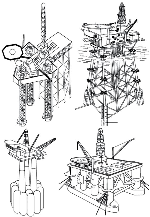
Inspection and repair depend on the type of structure and the material used. The types of platforms primarily used in the offshore industry are fixed with some variation and floating platforms. Examples of offshore structures are shown in Figure 4 and Figure 5.
Fixed platforms typically are of the type:
● fixed steel structures (jacket structures), which are mostly pile supported or suction anchor supported;
● concrete gravity-based structures;
● jack-ups; or
● monopile.
Floating platforms are in general dependent on their watertight integrity and station keeping in addition to their structural integrity to function. The most used types of floating structures in the offshore industry include:
● semi-submersible platforms (mostly in steel, but one in concrete exists);
● tension leg platforms (mostly in steel, but one in concrete exists);
● ship-shaped platforms and barge-shaped platforms (mostly in steel, but a few in concrete have been made); and
● spar platforms.
Structures must adhere to regional regulations (stationary structures) or to flag state regulations in combination with class society rules (mobile units). So-called mobile offshore units (MOUs) are typically at a location for a limited time and inspection and repair are often performed at a yard at regular intervals. These yard periods allow for inspection and repair to be performed in controlled circumstances, often in dry conditions or benign conditions. In comparison, inspection and repair of stationary structures requires inspection and repair to be performed in an offshore environment and often underwater by an ROV. Hence, inspection and repair are rather different for these two types of structures, both with regards to the regulatory regime and the environment in which the inspection and repair is performed.
1.3.1 Fixed Steel Structures
Fixed steel structures (jackets) consist of a steel spaceframe piled to the seabed (Figure 4 b), supporting a deck with space for drilling rigs, production facilities and crew quarters. Fixed steel
Figure 4 Examples of types of offshore structures: (a) is a jack-up placed alongside a jacket structure, (b) is a jacket structure, (c) is a concrete gravity-based structure and (d) is a semi-submersible unit. Source: Sundar, V. (2015), Ocean Wave Mechanics: Application in Marine Structures, © 2015, John Wiley & Sons.
structures are also used as a substructure for wind turbines. Steel jackets are usually made of tubular steel members. A typical six-legged steel platform is shown in Figure 4 b. Historically, the piles were driven directly through the legs and into the seabed. In more recent platforms the piles are typically connected to the legs by pile sleeves where the annulus between the sleeve and the pile is grouted. In a few cases, a specialized suction pile (bucket foundation) has been used, for example the Norwegian platforms Draupner 16/11-E and Sleipner T. In addition to the basic structure there are frames for the conductors, j-tubes, risers and caissons needed for production and operation. J-tubes are typically used to enable small diameter flowlines, electrical cables or pipeline bundles to be connected to the topside facilities. Steel structures are subject to ageing processes such as fatigue and corrosion and hence life extension is a key issue with regard to the structure itself.
(a)
(b)
(c)
(d)
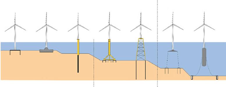
Grounded systems:
Floating systems:
Water depth: < 30 m> 60m 30–60m
Figure 5 Various forms of wind turbine substructures: (a) suction pile caisson, (b) gravity-based concrete foundation, (c) monopile, (d) tripod, (e) fixed steel structure (jacket), (f) tension leg platform, (g) spar buoy.
Source: Bhattacharya, S. (2019), Design of Foundations for Offshore Wind Turbines © 2019, John Wiley & Sons.
Jack-ups (Figure 4 a) are self-elevating units with a buoyant hull and several legs which when on location can be lowered to the seabed and raise the deck above the level of the sea thus creating a more stable facility for drilling and/or production. During operation in an elevated situation, jackups behave like a fixed platform. Jack-up rigs have been primarily used for exploratory drilling, but there are a few instances where they have also been used for production.
Monopiles (Figure 5 c) support the deck on a single pile / tower. These types of structures are particularly used for offshore wind energy production.
1.3.2 Floating Structures
Semi-submersible units (Figure 4 d) have hulls, together with columns and pontoons, with sufficient buoyancy to enable the structure to float. Semi-submersible platforms change draft by means of ballasting and de-ballasting (changing the water level in seawater tanks). They are normally anchored to the seabed by mooring systems, usually a combination of chain and wire rope. However, semi-submersibles can also be kept on station by dynamic positioning (DP), commonly used for semi-submersibles as drilling units and flotels in deep water. The hull supports a deck on which various facilities for drilling and production can be installed. Semi-submersible platforms are also being used for wind energy production, such as on the Kincardine wind farm in Scotland.
A tension leg platform (TLP) is of similar form to the semi-submersible platform but is vertically moored by tension legs, which decrease the vertical motion significantly. A TLP is designed with excess buoyancy to ensure that the tension in the legs remains in all operational conditions.
A spar platform consists of a single moored large-diameter vertical cylinder that is supporting the topside or a wind turbine. The cylinder is ballasted in the bottom (often by solid and heavy material) to provide stability. Spar-type of structures are increasingly being used for floating wind energy production.
A ship-shaped structure is a floating vessel similar in shape to a conventional ship, primarily used by the production and processing of hydrocarbons. These are often called a floating storage unit (FSU), a floating storage and offloading unit (FSO) or a floating production, storage and offloading unit (FPSO). The steel hull typically consists of plates in a main deck, side shells,
turn-of-bilge and a bottom shell in addtion to tank tops and longitudinal bulkheads (wing tank bulkhead and centreline bulkhead) and transverse bulkheads. These main platings together form the ship beam. In most cases these plates are stiffened by girders and stiffeners. The plates are exposed to the loading from hydrostatic and dynamic pressure, which is transferred to the stiffeners and girder beams and into the structure. Ship-shaped structures are usually moored to the seabed by chains or wire ropes, although they can also be held on station using a dynamic positioning system. These mooring systems will require underwater inspection and possibly repair.
Most of the details of floating structures can be inspected from the inside in near dry conditions and are, as such, not a part of this book. However, underwater inspection and repair of the mooring, anchors, outer skin, valves and attatchments are relevant and hence included in the book.
1.3.3 Concrete Platforms
Concrete is used in several different types of offshore structures, which include:
● gravity-based structures, or GBS (for example, the Norwegian platforms Statfjord A-C and UK platform Brent C);
● tension leg platforms, or TLP (the Norwegian platform Heidrun);
● spar platforms, particularly for wind energy production,
● semi-submersible platforms (the Norwegian platform Troll B);
● Jarlan walls enclosing concrete tanks (the UK platform Ninian and the Norwegian platform Ekofisk Tank);
● steel-concrete hybrid (the UK platform Ravenspurn); and
● articulated tower (used as a loading column on Maureen).
The first concrete structure to be installed in the Norwegian sector was the Ekofisk tank in 1973 and the first to be installed on the UKCS was Beryl Alpha in 1975. At the time of writing, there are 22 concrete gravity-based platforms, together with one concrete tension leg platform (Heidrun), one concrete semi-submersible platform (Troll B) and one concrete base for a steel upper section (Harding).
Due to the dominance of GBS-type structures, this book will mainly focus on these, but some aspects will apply for all types of concrete structures. The main parts of a concrete gravity-based structure (GBS) are:
● legs, towers and shafts;
● storage cells (caissons);
● steel-to-concrete transition;
● shaft-to-base junction;
● prestressing anchorages;
● splash zone;
● foundations; and
● cathodic protection system.
Most concrete structures rest on the seabed on a large caisson often with skirts that penetrate the seabed protecting the structure against horizontal and overturning forces (Figure 4 c). The size of the caisson and skirts depends on local soil conditions. The topside steel structure
is usually supported on up to four concrete columns/shafts extending from the caisson through the sea surface. The caisson can be divided into cells, which may be used as compartments for oil storage or as ballast. One or two of the columns are usually drill shafts supporting conductor frames and well-conductors. Some of the shafts, which may be water filled or dry, are normally outfitted mechanically.
1.4 Overview of this