
https://ebookmass.com/product/thoracic-imaging-therequisites-requisites-in-radiology-3rd-edition-jo-anne-o-


https://ebookmass.com/product/thoracic-imaging-therequisites-requisites-in-radiology-3rd-edition-jo-anne-o-
https://ebookmass.com/product/diabetologie-3e-edition-edition-louismonnier/
ebookmass.com

James
H. Thrall, MD
Radiologist-in-Chief Emeritus
Massachusetts General Hospital
Distinguished Juan M. Taveras Professor of Radiology
Harvard Medical School
Boston, Massachusetts
Breast Imaging
Cardiac Imaging
Emergency Imaging
Gastrointestinal Imaging
Genitourinary Imaging
Musculoskeletal Imaging
Neuroradiology Imaging
Nuclear Medicine
Pediatric Imaging
Radiology Noninterpretive Skills
Thoracic Imaging
Ultrasound
Vascular and Interventional Imaging
To my husband Bill and our children Sarah, John, and Bobby with whose love and support all is possible
To my parents
Anne and John O’Malley for their inspiration
Jo-Anne O’Malley Shepard
In memory of our friends and colleagues
Henry J. Llewellyn, MD (1937-2009)
Beatrice Trotman-Dickenson, MBBS (1957-2015)
Joan Curran Dow (1949-2016)
It is a pleasure to help introduce the Third Edition of Thoracic Radiology: The Requisites. Thoracic imaging is a cornerstone of radiology practice that touches more patients than any other area of sub-specialization in radiology. Many of the same technological innovations and advancements that have propelled other areas of radiology forward in the last several years have also substantially changed the landscape in thoracic imaging, making the publication of the Third Edition timely and important.
Dr. Jo-Anne O. Shepard is the editor of the new edition and has assembled a terrific team of co-editors and authors. In this regard, the Third Edition of Thoracic Radiology: The Requisites reflects an important trend in authorship. The original books were each written by a small number of people, many with only one or two authors. Over time, the breadth and complexity of each topic have increased to the point that a multi-author approach is now appropriate for the level of expertise required. Doctors Gerald F. Abbott, Jeanne B. Ackman, Subba R. Digmurthy, Mathew D. Gilman, Amita Sharma, and Carol C. Wu serve as Associate Editors for this edition. Additional contributing authors include Manudeep Kalra, Alexi Otraji, Melissa Price, Bojan Kovacina, Lan Qian (Lancia) Guo, Brett W. Carter, Mylene Truong, Christopher M. Walker, Susan Gutschow, Shaunagh McDermott, Efren J. Flores, Laura L. Avery, John W. Nance, Hristina Natcheva, Thomas Keimig, Jonathan Chung, Rydhwana Hossain, Victorine V. Muse, Milena Petranovic, Florian J. Fintelmann, Bradley S. Sabloff and Justin Stowell. It is difficult to imagine a stronger group of contributors. Dr. Shepard and her co-authors are to be congratulated on producing a high-quality book that will be both practical and manageable for the reader.
The format and layout of Thoracic Radiology: The Requisites remain largely intact with early chapters on technique and normal anatomy and chapters covering major diseases and conditions. However, several new chapters address advances in technology and provide for deeper coverage of increasingly specialized clinical applications. For example, in the interval since publication of the Second Edition of Thoracic Radiology: The Requisites, the National Lung Screening Trial (NLST) demonstrated that screening for lung cancer in a defined population saves lives. This
was a major milestone in medical practice that has created important opportunities for thoracic radiologists but also challenges related to adopting best practices for screening and correct application of the lung cancer staging system. Correspondingly there are two chapters in this book that address these issues, one on screening and one on staging.
The digital transformation in radiology is now substantially complete. This transformation is fully incorporated into the Third Edition of Thoracic Radiology: The Requisites, including a chapter that covers PET/CT and PET/MR. While PET/CT is well established in thoracic imaging, especially for cancer diagnosis and follow-up, the potential for PET/ MR is just becoming more widely available. Many of the chapters with familiar titles are now more richly illustrated with digital images with corresponding emphasis on highresolution cross-sectional methods. The associated improvements in both image quality and diagnostic capabilities are highlighted.
The Requisites books are not intended to be exhaustive. There are “mega” reference texts that catalog rare and unusual cases and that present different sides of controversies. Rather, The Requisites books are intended to provide information on the conditions that radiologists see every day, the ones that are at the core of radiology practice. In fact, one of the requests to authors is to not look up anything unusual or obscure but to put in the book what they teach their own residents every day at the workstation. Since the authors are experienced experts in their respective areas, this is predictably the most important material.
The Requisites series is now well over 25 years old and has served thousands of radiologists. The books are familiar and trusted friends to many people. It is my hope and expectation that radiology trainees as well as practicing radiologists seeking to refresh their knowledge will find the Third Edition of Thoracic Radiology: The Requisites a useful text.
James H. Thrall, MD Radiologist-in-Chief, Emeritus Massachusetts General Hospital Distinguished Taveras Professor of Radiology Harvard Medical School
It is an honor and a privilege to be the Editor of the Third Edition of Thoracic Imaging: The Requisites. The prior editions, edited by Theresa McLoud and Philip Boiselle, have been embraced by students and practitioners of thoracic imaging throughout the world as a reliable source for the essentials of state-of-the-art thoracic imaging.
Much has changed since the earlier editions in 1998 and 2010. Thoracic Requisites has been rewritten to encompass a host of new imaging and interventional techniques, up-todate disease classifications and staging, current approaches to diagnosis and management, and radiation dose reduction strategies. The content has been arranged into 25 focused chapters. An integrated approach to learning normal chest anatomy contains correlative radiographic and CT images. There is new material on acute and critical care imaging, including post-operative complications, trauma, ICU diagnosis, and implantable devices. There is extensive new information on thoracic MRI indications, protocols, and case material, as well as expanded content on interstitial lung disease, infections, and vascular diseases. Updated lung cancer coverage includes new tumor staging and diagnostic techniques, lung cancer screening, and updated
pulmonary nodule management strategies. State-of-the-art interventional content includes diagnostic thoracic biopsy techniques, fiducial placement to aid VATS surgical resection of small pulmonary nodules, and ablative therapies for local control of thoracic tumors. More than 1000 new images encompass current digital radiographs, MDCT images including HRCT, and dual energy CT scanning, FDG-PET/ CT, and PET/MRI. The content has been enhanced by many new diagrams and illustrations in full color. New tables and boxes contain concise differential diagnoses and diagnostic information.
In the tradition of the Requisites series, Thoracic Imaging is designed to provide a requisite curriculum in thoracic imaging for residents and fellows in radiology and allied specialties, as well as practicing radiologists and other healthcare providers. Thoracic imaging is growing as a specialty, and the demand for expertise is increasing within both hospital and community practices. Thoracic Imaging: The Requisites will be an invaluable educational resource for all involved in the diagnosis of thoracic disease.
Jo-Anne O. Shepard, MD
Gerald F. Abbott, MD, FACR
Associate Professor of Radiology
Harvard Medical School;
Radiologist, Thoracic Imaging and Intervention Department of Radiology
Massachusetts General Hospital Boston, Massachusetts
Chapter 2, Normal Anatomy and Atelectasis
Chapter 16, Mycobacterial Infection
Chapter 17, Approach to Diffuse Lung Disease: Anatomic Basis and High-Resolution Computed Tomography
Jeanne B. Ackman, MD, FACR
Assistant Professor of Radiology
Harvard Medical School;
Radiologist, Thoracic Imaging and Intervention Director, Thoracic MRI
Department of Radiology
Massachusetts General Hospital Boston, Massachusetts
Chapter 3, Thoracic Magnetic Resonance Imaging: Technique and Approach to Diagnosis
Chapter 5, The Mediastinum
Chapter 7, The Pleura, Diaphragm, and Chest Wall
Chapter 13, Thoracic Trauma
Laura L. Avery, MD
Assistant Professor of Radiology
Harvard Medical School;
Associate Director, Emergency Radiology
Radiology Clerkship Director Department of Radiology
Massachusetts General Hospital Boston, Massachusetts
Chapter 13, Thoracic Trauma
Brett W. Carter, MD
Assistant Professor of Diagnostic Radiology
Quality Officer, Diagnostic Imaging Director, CT and MRI
Clinical Co-Director, Quantitative Imaging Analysis Core
The University of Texas MD Anderson Cancer Center
Houston, Texas
Chapter 6, The Airways
Chapter 20, Obstructive Lung Diseases
Chapter 21, Pulmonary Tumors and Lymphoproliferative Disorders
Jonathan Chung, MD
Associate Professor of Radiology
Interim Chief of Quality
Section Chief, Thoracic Radiology
Department of Radiology
The University of Chicago Medicine
Chicago, Illinois
Chapter 18, Diffuse Lung Diseases
Subba R. Digumarthy, MD
Assistant Professor of Radiology
Radiologist, Thoracic Imaging and Intervention Division Quality Director, Thoracic Imaging Department of Radiology
Massachusetts General Hospital Boston, Massachusetts
Chapter 1, Radiological Techniques and Dose Reduction
Strategies in Chest Imaging
Chapter 4, PET-CT and PET-MRI: Technique, Pitfalls, and Findings
Chapter 12, The Postoperative Chest
Chapter 19, Pneumoconioses
Chapter 22, Incidental Pulmonary Nodule
Chapter 24, Lung Cancer Staging
Florian J. Fintelmann, MD
Assistant Professor of Radiology
Harvard Medical School;
Radiologist, Thoracic Imaging and Intervention Department of Radiology
Massachusetts General Hospital Boston, Massachusetts
Chapter 25, Interventional Techniques
Efren J. Flores, MD
Instructor of Radiology
Harvard Medical School; Radiologist, Emergency Radiology Director, Radiology Community Health Improvement Department of Radiology
Massachusetts General Hospital Boston, Massachusetts
Chapter 13, Thoracic Trauma
Matthew D. Gilman, MD
Assistant Professor of Radiology
Harvard Medical School; Associate Director, Thoracic Imaging and Intervention Associate Director, Cardiothoracic Imaging Fellowship Department of Radiology
Massachusetts General Hospital Boston, Massachusetts
Chapter 8, Congenital Thoracic Malformations
Chapter 9, Thoracic Lines and Tubes
Chapter 11, Pulmonary Embolus and Pulmonary Vascular Diseases
Lan Qian (Lancia) Guo, MD, FRCP(C)
Radiologist, Division of Cardiothoracic Imaging
Department of Medical Imaging
University of Toronto Sunnybrook Health Sciences Centre Toronto, Ontario, Canada
Chapter 5, The Mediastinum
Chapter 7, The Pleura, Diaphragm, and Chest Wall
Amita Sharma, MD
Assistant Professor of Radiology
Harvard Medical School
Radiologist, Thoracic Imaging and Intervention
Department of Radiology
Massachusetts General Hospital Boston, Massachusetts
Chapter 17, Approach to Diffuse Lung Disease: Anatomic Basis and High-Resolution Computed Tomography
Chapter 18, Diffuse Lung Diseases
Chapter 23, Lung Cancer Screening
Jo-Anne O. Shepard, MD
Professor of Radiology
Harvard Medical School; Director, Thoracic Imaging and Intervention Director, Cardiothoracic Imaging Fellowship
Massachusetts General Hospital Boston, Massachusetts
Chapter 2, Normal Anatomy and Atelectasis
Chapter 6, The Airways
Chapter 16, Mycobacterial Infection
Chapter 20, Obstructive Lung Diseases
Chapter 23, Lung Cancer Screening
Chapter 25, Interventional Techniques
Bradley S. Sabloff, MD
Professor of Diagnostic Radiology
University of Texas MD Anderson Cancer Center
Houston, Texas
Chapter 21, Pulmonary Tumors and Lymphoproliferative Disorders
Justin Stowell, MD
Resident
Department of Radiology
University of Missouri–Kansas City
Kansas City, Missouri
Chapter 8, Congenital Thoracic Malformations
Mylene T. Truong, MD
Professor of Diagnostic Imaging
Section Chief of Thoracic Imaging
University of Texas MD Anderson Cancer Center
Houston, Texas
Chapter 6, The Airways
Chapter 21, Pulmonary Tumors and Lymphoproliferative Disorders
Christopher M. Walker, MD
Associate Professor of Radiology University of Missouri–Kansas City; Saint Luke’s Hospital Kansas City, Missouri
Chapter 8, Congenital Thoracic Malformations
Chapter 10, Acute Thoracic Conditions in the Intensive Care Unit
Carol C. Wu, MD
Associate Professor of Diagnostic Radiology
University of Texas MD Anderson Cancer Center Houston, Texas
Chapter 6, The Airways
Chapter 20, Obstructive Lung Diseases
Chapter 21, Pulmonary Tumors and Lymphoproliferative Disorders
Mannudeep K. Kalra, Alexi Otrakji, and Subba R. Digumarthy
This chapter reviews various x-ray–based techniques used in thoracic imaging, including radiography, fluoroscopy, digital tomosynthesis, and computed tomography (CT).
Merely 1 year after discovery of x-rays by Wilhelm Konrad Roentgen, calcium tungstate was chosen as the material for the first screen cassettes based on Thomas Edison’s assessment of about 5000 chemicals for their light-producing capabilities upon exposure to x-rays. For the next 75 years, conventional radiography remained confined to the radiographic films sandwiched between two calcium tungstate–based fluoroscopic screens. It was not until the mid-1970s that the first computer-based processing of radiographic images began to emerge with concomitant introduction of rare earth chemicals into intensifying screens, which had better x-ray absorption and lower radiation dose requirements.
The earlier versions of computed radiography (CR) used the cassettes with new fluorescent materials, which retained the information of x-ray exposure as a latent image. This information was retrieved by stimulation with a thin focused laser beam, which resulted in re-emission of light. This light was captured with light-sensitive diodes and converted to electrical signals stored and processed with computers. Although initial versions of CR required much higher radiation exposure, subsequent refinements in the detectors resulted in considerable decreases in radiation doses. The cassette-based CR systems also required specific readout stations, which have also decreased in size and cost. These systems are in common use because of their flexibility and lower costs.
Developments in CR technology finally led to direct digital radiography (DR), with electronic detectors. In the direct conversion type of DR system, the incident x-ray photons interact with photodiodes and generate electrons, which form digital images. In the indirect conversion type, x-ray photons interact with a scintillator to generate light photons, which then subsequently interact with photodiodes to release electrons to form digital images (Fig. 1.1).
The indirect conversion type of DR system is most commonly used in chest radiography, and commonly used scintillation detectors are cesium iodide and gadolinium
oxysulfide. The direct type of DR systems is used in mammography units. Compared with CR, DR systems are faster, allow more efficient throughput, have better image quality, and have higher radiation dose efficiency. For these reasons, mobile and wireless DR systems have immense applications in critical care settings, emergency departments, and intraoperative imaging.
Digitization of radiographic images with CR and DR has also enabled benefits in the form of electronic image storage and display on the picture archiving and communication system (PACS) as well as image manipulations such as adjustment of brightness and contrast, edge enhancement, inverted image display, zooming, and subtraction capabilities. Modern radiography units are more radiation dose efficient and use automatic exposure control techniques to terminate the radiographic exposure when the desired quality is reached. It is also important that the operators use appropriate guidelines (e.g., centering, breath-hold instruction, and coning) to minimize unnecessary repetition of radiographs.
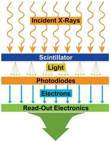
As opposed to readout workstations for CR, which implied some readout time, with DR systems, radiographs could be ready for interpretation in as little as 5 seconds after their acquisition (Fig. 1.2).
The plain chest radiograph is the most commonly performed imaging procedure in most radiology practices, constituting between 30% and 50% of studies. The standard routine chest radiograph consists of an erect radiograph made in the posteroanterior (PA) projection and a left lateral radiograph, both obtained at full inspiration. In the standard PA projection, the patient faces the cassette, and the x-ray tube is located 6 feet behind the patient. The arms are directed away from the chest with the hands resting on the waist. This technique prevents magnification of anterior structures such as the heart. The full inspiration allows complete expansion of the lungs and separation of pulmonary blood vessels to improve detection of pathology. In an ideally performed standard radiograph, the trachea is in midline projection over the spine and is equidistant from the heads of both clavicles. The lung apices, the lateral costophrenic (CP) angles of the lungs, and the diaphragm are completely visualized, and the diaphragm lies at or below the anterior sixth and posterior ninth ribs.
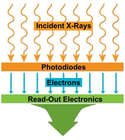
1.1 Digital radiography (DR). Schematic representation of direct conversion type of DR system (A) and indirect conversion type of DR system (B)
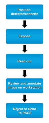
FIGURE 1.2 Workflow chart for computed radiography (CR) (A) and digital radiography (DR) (B) systems. PACS, Picture archiving and communication system.
Chest radiographs should be exposed using a high kilovoltage (kV) technique, usually in the range of 100 to 140 kV. With this technique, a grid or air gap is required to reduce scatter radiation. The main advantage of this technique is that the bony structures appear less dense, permitting better visualization of the underlying parenchyma and the mediastinum. The only drawbacks are the decreased detectability of calcified lesions and loss of bony detail.
With the emergence of CT, the use of additional projections and views in chest radiography has precipitously decreased because additional information in doubtful circumstances is typically resolved with cross-sectional imaging. Furthermore, emerging literature also demonstrates the
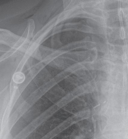
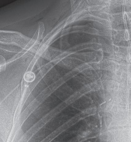
use of digital tomosynthesis in these situations. Additional views of the chest may be required in special instances. Shallow oblique radiographs (15 degrees) may be useful in confirming the presence of a suspected nodule. Forty-five–degree oblique radiographs can be used for the detection of asbestos-related pleural plaques. Apical lordotic views project the clavicles above the chest, improving visualization of the apices and the middle lobe, particularly in cases of middle lobe atelectasis. Lateral decubitus radiographs (Fig. 1.3) can be used to determine the presence or mobility of pleural effusion and to detect small pneumothorax, particularly in patients who are confined to bed and unable to sit or stand erect. A PA radiograph done with nipple markers is useful
ABFIGURE 1.7 Edge enhancement technique. The tip of the right peripherally inserted central catheter (PICC) line is difficult to see on standard chest radiograph (A). With edge enhancement technique (B), the PICC line and its tip are better visualized (arrow)
exposure to body habitus. Fluoroscopic time should be kept to the minimum, and the exposure factors should be recorded.
In digital tomosynthesis, multiple projections (about 60) of very low-dose x-rays are obtained through the region of interest during a breath-hold of 10 seconds. The acquired data are then reconstructed into contiguous coronal images. At total estimated effective dose of about 0.12 mSv, the radiation dose from digital tomosynthesis is higher than typical PA chest radiographs (0.02 mSv) but significantly lower than most chest CT examinations (2–6 mSv). Compared with plain radiography, digital tomosynthesis provides superior lesion detectability from noise reduction, better depth assessment, and superior contrast resolution. Although the driving application of chest digital tomosynthesis is improved detection of pulmonary nodules over conventional radiography, several other applications have been assessed as well—for example, suspected interstitial lung disease, cystic fibrosis, airway evaluation, and evaluation of thoracic skeleton fractures. Studies have shown that digital tomosynthesis can help detect more pulmonary nodules smaller than 9 mm in diameter compared with combined PA and lateral chest radiographs (Fig. 1.8).
Similar to conventional radiography, CT also uses x-rays generated from an x-ray tube. Although x-rays in conventional radiography are projected from one direction only, the x-ray tube in CT revolves 360 degrees around the patient while continuously projecting x-rays so that cross-sectional images of the body can be generated. These x-rays traverse through the patient’s body and reach the detector assembly, where they create a signal. This signal is represented by attenuation value or coefficient, which is a measure of attenuation of x-rays as it traverses through the material or body part being scanned.
The Hounsfield units (HU) or CT numbers are arbitrary units that represent the average of all attenuation values in a voxel of image. The voxel represents a three-dimensional (3D) volume element in the object consisting of each individual number in the image matrix. The Hounsfield value of water is considered “0.” Fat, lung, and air have negative values (-50 to 100, -850 to -910, and -1000, respectively). Soft tissues, bone, and metals have positive values (45 to 65, 700 to 1500, and over 2000, respectively).
The earliest “step-and-shoot” CT scanners involved x-ray tube and detector assemblies with direct wire attachments, which meant that after each revolution, the wires had to “unwind” before rescanning. In the early 1990s, the x-ray tube and detector elements were mounted on a “slip ring” gantry system that was connected to the wires. This arrangement meant that both x-ray tube and detector elements could continuously revolve around the patient while the table moved in or out of the gantry aperture. Dubbed as spiral or helical CT, this enabled a much faster coverage compared with its predecessor step-and-shoot CT systems. Because there was only a single row of detectors along the patient length in the earlier helical scanners, only one image could be created per 360-degree gantry revolution.
Helical CT experienced a breakthrough in the 1990s, when multiple rows of finer detectors were introduced into the detector assembly along the patient length, enabling multiple images or slices per gantry revolution of the x-ray tube. These multidetector-row CT (MDCT) scanners began with a modest 2 to 16 rows, enabling two to four images per 360-degree revolution and led to slice wars among different CT vendors in the early 2000s. Modern MDCT scanners (Box 1.1) can now generate 64 to 640 overlapping images per gantry revolution, encompassing a length of up to 16 cm per gantry revolution!
In addition to wide area coverage, the finer detector rows in modern MDCT scanners can generate submillimeter images (up to 0.5 mm thickness) of the whole chest in under 1 second. Wide area coverage, fast gantry revolution times down to a quarter of a second, and high scanning
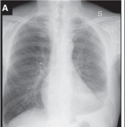
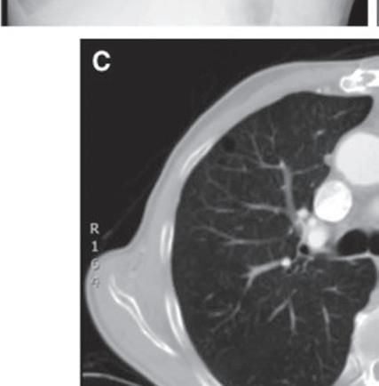
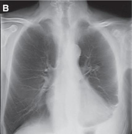
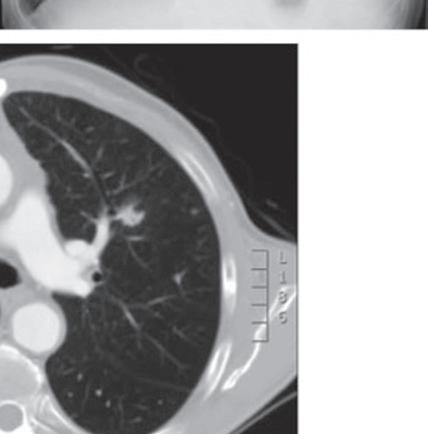
FIGURE 1.8 Digital tomosynthesis. A nodule in the left mid-lung zone on a standard radiograph (arrow) (A) is better seen on a radiograph obtained with the digital tomosynthesis technique (B). Chest computed tomography demonstrates the lung nodule in the left upper lobe (C). (From Terzi A, Bertolaccini L, Viti A, et al: Lung cancer detection with digital chest tomosynthesis: baseline results from the observational study SOS. J Thorac Oncol 2013;8(6):685-692.)
speeds have enabled users to substantially reduce or eliminate motion artifacts from CT images. In fact, some MDCT scanners can now enable free-breathing scanning of the entire chest in less than half a second.
X-ray tubes in newer MDCT scanners have also overcome tube heating issues for nonstop extended coverage examinations (e.g., multiple body part CT angiography) and for large patients. Simultaneous improvements in detector assemblies in certain MDCT scanners with better integration of electronics have helped improve scanner efficiency and have decreased image noise at low-dose levels as well as in very large patients.
Because of simultaneous improvements in computational capabilities, thanks to the video gaming industries and more accurate and efficient methods of image reconstruction, iterative reconstruction techniques have been introduced
on most modern MDCT scanners. These techniques result in less image noise and fewer artifacts compared with the conventional filtered back projection methods, which in turn enables users to reduce radiation dose while maintaining or even enhancing image quality.
Although chest CT is the imaging modality of choice for the evaluation of several clinical indications, chest radiography remains the most commonly performed test in the radiology department for assessment of the chest in both inpatient and outpatient settings. Compared with chest CT, chest radiography has a much lower cost and is associated with a substantially lower radiation dose.
Most DECT datasets can be used to generate additional virtual monoenergetic images (typically between 40 and 60 keV [kilo electron volts]) that have high-contrast enhancement because they are close to the k-edge of the iodine. To minimize contrast streak artifacts and image noise in larger patients, higher keV images ( >70 keV) may be necessary. Iodine or pulmonary blood volume images represent material decomposition images (obtained from subtracting water from contrast-enhanced DECT images) that provide information on distribution of iodine in the lungs or remainder of the chest depending on the selected settings. The absolute iodine concentration expressed as milligrams per milliliter can be calculated from pulmonary blood volume images (Fig. 1.10). One can also generate water or virtual noncontrast images from contrast-enhanced
DECT by subtracting iodine from the image datasets to differentiate calcium, hemorrhage, or high-protein content from iodinated contrast (Fig. 1.11). The DECT technique also allows generation of higher keV images, which can help reduce artifacts with metallic implants or prostheses (Fig. 1.12).
Recent publications on dual-source DECT for chest applications have reported dose parity with single-energy CT protocols. With rapid kV switching DECT, the radiation dose can be higher than for single-energy CT. Given the importance of maintaining radiation dose levels at as low as reasonably achievable (ALARA principle), it is important
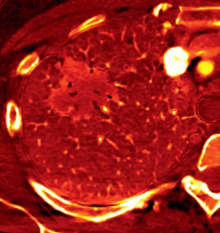
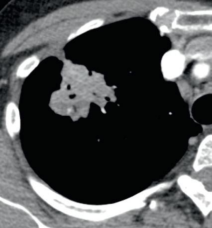
FIGURE 1.10 Estimation of iodine density in lung cancer. A standard computed tomography image (A) demonstrates an enhancing mass in the right upper lobe, particularly in the anterior aspect of the mass. The absolute iodine concentration expressed as milligrams per milliliter can be calculated from pulmonary blood volume (PBV) images (B)
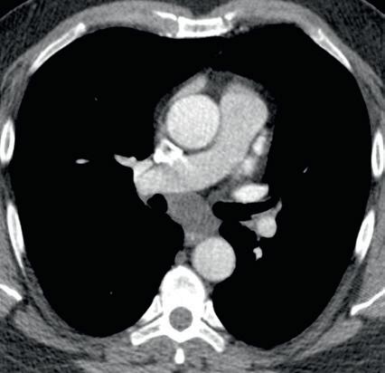
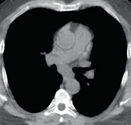
FIGURE 1.11 Virtual noncontrast image. A soft tissue density mass is seen in the subcarinal region on the 140-kV image (A). On the virtual noncontrast (VNC) image (B), after iodine substraction, there is no change in the density of the subcarinal mass, and therefore there is no evidence for enhancement. This mass is consistent with a nonenhancing bronchogenic cyst.
compared with other body regions as well. Likewise, as discussed in the subsequent sections, chest CT examinations are also amenable to effective clinical indication–based protocols and radiation dose reduction.
Optimization of radiation dose for CT begins with determining the appropriateness and justification of CT for a given clinical indication. When chest CT is likely to provide diagnostic and treatment-changing information, it should not be withheld for concerns of radiation dose regardless of patient age or gender. When CT is unlikely to provide meaningful diagnostic information, the lowest dose CT results from avoiding the CT altogether. Several resources are available for determining the appropriateness of chest CT for different clinical scenarios from several organizations such as the ACR, Royal College of Radiologists, and European Commission referral guidelines. In addition, online decision support programs are available to aid referring physicians in ordering the most appropriate imaging test for a given clinical indication. After the appropriateness is established, the next step in radiation dose optimization for CT involves modification of scan parameters based on clinical indication and patient size.
This section discusses the relationship of CT scan parameters with image quality and radiation dose. Box 1.3 provides a list of important scan parameters for chest CT.
Major parameters have profound effects on CT radiation dose. Other parameters have variable effects on radiation dose depending on the CT scanner and vendor.
Tube current (measured in milliamperes [mA]) is the most commonly adjusted scan parameter for adjusting image quality and radiation dose. This is because there is a direct linear relationship between the applied tube current and the radiation dose. Thus, a 50% increase in tube current increases the radiation dose by 50% if other scan parameters are not changed. Likewise, a 50% decrease in tube current decreases the radiation dose by half. CT scanners can operate with fixed tube current specified by the user. Different tube currents are needed for different clinical indications and patient sizes.
Most chest CT examinations on MDCT scanners must be performed with automatic exposure control (AEC) techniques, which automatically adjust tube current based on patient size as estimated from x-ray attenuation during acquisition of scout or planning radiographs. For a smaller or less dense body region, these AEC techniques automatically use less tube current when the x-ray tube revolves around the patient in the x–y plane (angular modulation), along the patient length or z-axis from one scan position to the next (longitudinal modulation), or in both planes (combined angular and longitudinal modulation). Conversely, these techniques increase the tube current for a larger or denser body region. Basically, AEC techniques help adjust the tube current automatically based on the image quality that users specify in the form of noise index (GE), quality reference mAs (Siemens), or standard deviation (Toshiba). The image quality settings should be specified based on clinical indications. When low-radiation-dose CT is desired (e.g., for lung nodule follow-up CT), a lower image quality is specified so that AEC uses a lower tube current.
MAJOR PARAMETERS
Scan length (cm)
Number of phases (inspiration, expiration, prone)
Tube current (mA)
Tube potential (kV)
Gantry rotation time (seconds)
Detector configuration (mm)
Table speed (mm/rotation or mm/sec)
OTHER PARAMETERS
Beam pitch (no unit)
Reconstructed section thickness (mm)
Reconstruction method
Filtered back projection (FBP)
Iterative reconstruction techniques (IRT)
Conversely, when better image quality is needed (e.g., routine chest CT protocols), a relatively higher image quality is specified. Studies have shown that AEC techniques can enable substantial dose reduction (>50%) compared with fixed tube current–based CT protocols.
Tube potential (measured in kilovoltage [kV]) has a more profound effect on radiation dose than tube current. In addition to radiation dose reduction, lower tube potential also increases the image contrast (brightness of intravenous [IV] contrast), an effect not seen with tube current. Traditionally, chest CT examinations were performed at 120 kV. Most nonobese patients should be scanned at 80 to 100 kV for chest CT. Most young children should be scanned at 80 kV to reduce radiation dose while obtaining sufficient contrast enhancement with lower contrast volume and rate of injection.
On most CT scanners, users still need to manually select an appropriate kV for scanning, although some modern MDCT now offer automatic kV selection techniques (KV Assist, GE; Care kV, Siemens) to enable automatic selection of the lowest tube potential while maintaining image quality. This selection is based on patient size (again coming from the initial scout or planning radiograph) and specified type of CT examination (noncontrast, postcontrast vs CT angiography). Lower tube potential (<120 kV) in adult patients undergoing chest CT has also increased with the availability of iterative reconstruction techniques, which help improve the quality of images acquired at lower tube potential or tube current. Some of the advanced MDCT scanners have powerful x-ray tubes to deliver higher tube current at lower tube potential so that advantages of lower tube potential in terms of radiation dose reduction and image contrast improvement can be extended to larger patients as well.
This parameter alludes to the time it takes for the x-ray tube to complete one 360-degree rotation around the patient. If other scan parameters are kept constant, a faster gantry rotation time will imply a shorter scan duration and therefore less radiation dose. Most chest CT scans, particularly on MDCT scanners, regardless of clinical indications, should be performed at a gantry rotation time of less than