ListofFigures
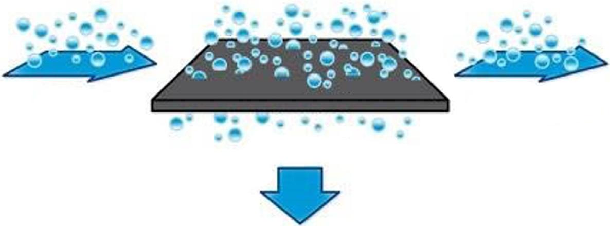
Fig.1.1Generalprocessofapressure-drivenmembrane
Fig.1.2Schematicdiagramofthefiltrationspectrumofrelatedseparationprocessesandseparated
Fig.1.3Demulsificationphenomenaofoil-in-water(O/W)emulsionsusingamembranecoalescence process
Fig.2.1Chemicalstructureofcelluloseacetate
Fig.2.2Schematicrepresentationofosmosisandreverseosmosisprocesses
Fig.2.3ChemicalstructureofpolyamideformedbyinterfacialpolymerizationbetweenMPD
Fig.2.4Schematicdepictionofsecond-generationthin-film-compositemembranestructure
Fig.2.5Processforpreparationofapolymersupportmembrane
Fig.2.6Processforpreparationofthin-film-compositeROmembrane
Fig.2.7Schemeofpolyamidedepositionovertheporoussupportmembrane
Fig.2.8ThetransportprocessofsaltandwaterfluxthroughtheROmembrane.(A)Defect-free ROmembrane;(B)ImperfectROmembrane
Fig.2.9Modulearrayconnectedinserieswithinasinglepressurevessel(A)andpressurevessels connectedinparallel(B)
Fig.3.1(A)Chemicalstructureofmauveand(B)differencebetweendyesandpigments
Fig.3.2Chemicalstructureofreactiveblack5
Fig.3.3Schematicoftheexperimentalsetup
Fig.3.4SchematicoftheNFmembranepolyamidelayerwithandwithouttheCNTlayer(top)andthe SEMcross-sectionalimageoftheTFCmembranewiththeCNTinterlayer(bottom)
Fig.3.5FESEMimageof(A)cross-sectionalimageoftheHFNFmembraneand(B)theinnersurface oftheHFNFmembraneafterthedyeconcentrationexperiment
Fig.3.6Schematicillustrationofthelab-scaleFO-MDhybridprocess
Fig.3.7(A)Dyeremovalefficacyand(B)fluxofpristineandnanocompositemembranes
Fig.3.8DyerejectionpropertiesofPAN-basedmembraneswithdifferentMWCOs
43
45
46
47
48
Fig.3.9SchematicexperimentalsetupofamembranephotocatalyticreactorcoupledwithtightUF49
Fig.4.1Schematicdiagramofpollutantdegradationbyaphotocatalyst.AlthoughTiO2 isusedasthe model,themechanismofthephotocatalyticprocessformostmetaloxideandsemiconductor photocatalystsisthesame
58
Fig.4.2Formationofaparticlebridgeattheneckofthemembranepores 63
Fig.4.3Schematicdiagramofamixedmatrixmembrane 64
Fig.5.1SchematicillustrationofMEUFforheavymetalrecovery 73
Fig.5.2HomogeneousversusheterogenousIEMs.Ionicpathwaysin(A)homogeneousand (B)heterogeneousIEMs,(C)permselectivity,and(D)arealresistances
79
Fig.5.3Schematicillustrationofelectrodialysis(ED).(A)Deionizationprocessand(B)EDsetup81
Fig.5.4Electrodeionization(EDI).(A)Schematicillustrationofdeionizationprocessand(B)stack construction
Fig.5.5Schematicillustrationofmembranecapacitivedeionization(MCDI)process.(A)adsorption and(B)desorption/electroderegeneration
84
87
Fig.5.6Membranedistillation(MD).(A)DesalinationprocessinMD,(B)directcontactMD, (C)sweepinggasMD,(D)vacuumMD,and(E)airgapMD
Fig.5.7Watercontactanglesonmembranesurfacewithvariouswettability
Fig.6.1Pathwayof(A)conventionalnitrification-denitrificationand(B)simultaneous nitrification-denitrification
Fig.6.2Schematicoftheosmosisprocess
Fig.6.3Schematicofthereverseosmosisprocess
Fig.6.4Schematicofacross-flowsystem
Fig.6.5Schematicofadead-endsystem
Fig.6.6AnMBRconfigurations(A)externalcross-flowand(B)submerged/immersedconfigurations112
Fig.6.7ThechallengesoftheFOprocess
Fig.6.8SchematicofaTFCmembrane
Fig.6.9ThecharacteristicsofaTFNmembrane
Fig.6.10HeatandmasstransferintheMDprocess
Fig.6.11DifferenttypesofMDconfigurations.(A)DCMD,(B)AGMD,(C)SGMD,and(D)VMD120
Fig.7.1Pervaporation(PV)system
Fig.7.2Membranedistillationconfigurations:(A)directcontactmembranedistillation(DCMD); (B)airgapmembranedistillation(AGMD);(C)vacuummembranedistillation(VMD), and(D)sweepgasmembranedistillation(SGMD)
Fig.7.3Schematicdiagramofavacuummembranedistillation(VMD)setupbyYaoetal.
Fig.8.1BriefoverviewofFO
Fig.8.2Drawsoluteselectionguide
Fig.8.3Membraneselectionguide
Fig.9.1Conceptofcarboncaptureandstorage(CCS)
Fig.9.2Numberofreferenceswhosekeywordforeachyearis“Polymermembraneandacidicgas”176
Fig.9.3Gasseparationmechanismsinseparationmembranes 177
Fig.9.4Separationofmixturesofacidicandothergasesusing(A)acidicgasrejectivemembranes, and(B)acidicgaspermselectivemembranes
179
Fig.9.5Chemicalstructuresofpolyethylene(PE),polydimethylsiloxane(PDMS),poly(1trimethylsilyl-1-propyne)(PTMSP),tetrafluoroethylene(TFE)/perfluoromethylvinylether (PMVE)copolymer,teflonAF2400,polycarbonate(PC),andpolysulfone(PSF) 184
Fig.9.6Chemicalstructuresofnylon6,celluloseacetate(CA),poly(etherurethaneurea), andfluorine-containingpolyimides(6FDA-HAB) 185
Fig.9.7Chemicalstructuresofpolymersofintrinsicmicroporosity(PIM),thermallyrearranged(TR) polymer,and1-butyl-3-methylimidazolium(bmim)-basedionicliquids 186
Fig.9.8Relationshipbetweencarbondioxide,nitrogen(A),andhydrogensulfide(B)permeability ofpolymericmembranes 187
Fig.10.1Robeson’supperboundcorrelationforO2/N2 separation
Fig.10.2Polymer-basedmembranematerialsforO2/N2 separation
Fig.10.3SynthesisrouteandchemicalstructureofmonomersforPIMs
Fig.10.4Thermalrearrangementmechanism,(A)TR-α polymerand(B)TR-β polymer
Fig.10.5Schemeforfacilitatedtransportofgaseousmoleculesbyacarrier(complex)througha membrane:(A)liquidmembranewithamobilecarrier;(B)solidmembranewithafixed carrier
192
194
198
201
203
Fig.10.6ComparisonofO2/N2 separationperformanceofsomepolymericmembranes
Fig.11.1Thestructuresofgasseparationmembranes
Fig.11.2Schematicofapolymericflatsheetmembrane
Fig.11.3Schematicofapolymerichollowfibermembrane 220
Fig.11.4Generaltypesofmodulesusedforgasseparationprocesses:(A)plate-and-framemodule, (B)spiral-woundmodule,and(C)shellandtube
Fig.11.5Solution-diffusionmechanisminadensemembrane
Fig.11.6Schematicofanintegrallyasymmetricmembrane
Fig.11.7Preparationofintegrallyasymmetricflatsheetandhollowfibermembranesviaphase inversionmethod 225
Fig.11.8Schematicofathin-film-compositemembrane 227
Fig.11.9(A)SchematicdiagramoftheprocedurefortheproductionofaPAmembranederived fromMPDandTMCviaIP(B)chemicalreactionofMPDandTMCmonomerstoproduce aPAoligomerandHCl 228
Fig.11.10Robesongraphstocomparedifferentkindsofmembranesforgasseparation 229
Fig.11.11Schematicsofpolymer/inorganicfillermixedmatrixmembranes.(i)Symmetricflatdense mixedmatrixmembrane.(ii)Asymmetrichollow-fiberwithamixedmatrixselectiveskin230
Fig.11.12IllustrationofdifferenttypesofMMMs.(A)Polymerandinorganicphasesconnectedby covalentbonds,and(B)polymerandinorganicphasesconnectedbyvanderWaalsforceor hydrogenbonds 230
Fig.11.13Schematicofvariousorganic-inorganicinterfacemorphologiesofMMMs 232
Fig.11.14IdealMMM (leftside),(A)interfacevoid,and(B)rigidifiedpolymerlayeraroundthe nanoparticle (rightside) 233
Fig.11.15BCCstructureconsideredforparticledistributioninMMM 235
Fig.11.16SchematicillustrationofexpectedmorphologiesofMMMsHNT/PEIacrossadenseselective skinlayer;Case(I)ideal,Case(II)void(yellow-coloredspace surroundingthefilleristhe void),Case(III)rigidification(blue-coloredspace showstherigidifiedregion),Case(IV) blocking(blacktips showstheblockedparts),andCase(V)blocking+void
Fig.11.17ComparisonbetweenthesmallporesizefillerMMMmorphologydiagram (blackarrows alongwithitalicblackwords) proposedbyMooreandKorostothelargeporesizefiller MMMmorphologydiagramproposedbyHashemifardetal. (colorfulareaalongwithred boldwords)
Fig.11.18GeneralproceduresfollowedtoproduceasymmetricMMMs
Fig.11.19Cross-sectionalSEMimagesof(A)PC/zeolite4A(20%)and(B)PC/pNA(2%)/zeolite 4A(20%)
Fig.11.20SEMcross-sectionviewofthepolyacrylonitrile(PAN)supportmembrane.(A)Crosssection,(B)enlargedcross-section,(C)outerskinlayer,(D)outersurface,(E)outer-inner interface,and(F)innersurface
Fig.11.21TEMimagesofpoly(etherimide)nanocompositemembranescontainingdifferentweight fractions(10,20,30)ofthreefumedsilica(TS610,TS530,TS720).Atlowfumedsilica content,nanoparticlesarewelldistributedinthepolymermatrix
Fig.11.22TGAplotforpurepoly(4-methyl,2-pentyne)(PMP),fumedsilica(FS),and polyoctatrimethylsilsesquixane(POSS)nanoparticlesandnanocomposite membranes.POSSdecomposedquicklywhileFShadalowweightlossataspecific temperaturerange
236
237
240
243
244
245
246
Fig.11.23DSCplotsofthepurepolyurethane(PU)andpolyether-basedPU-silicananocomposites247
Fig.11.24AFManalysisfor(A)polysulfone(PSf)substratewhile(B),(C),and(D)aremodifiedPSf membraneswithdifferentmonomerconcentrationsforinterfacialpolymerization 248
Fig.11.25FTIRplotofpuresilica,purepolyurethane(PU),andpolyether-basedPU-silica nanocomposites.Inthisplot,eachpeakisrelatedtoaspecificbond 249
Fig.11.26Experimentalset-upofgaspermeationtests
Fig.11.27Experimentalset-upofgaspermeationtestatconstantvolume
Fig.11.28Experimentalset-upformeasuringthesolubilityofpuregasinthemembrane
Fig.11.29CO2 membraneseparationplantfromNewpointGas,LLC
Fig.11.30CO2/CH4 upperboundplotfornewpolymermaterials
Fig.11.31HydrogenrecoveryfromammoniapurgestreambyPrismmembranesplantthatinstalledin 1979withcapabilityofpurehydrogenrecoverybyabout90%
Fig.11.32O2/N2 upperboundplotfornewpolymermaterials,TRpolymers(⧫),PIMs(n), TBDA-SBI-P(▲)
Fig.11.33ImageoftheLPGrecoveryunitfromoff-gasinstalledbyMembraneTechnologyand Research(MTR)
Fig.11.34CO2 permeanceinanasymmetricPES/PIhollowfibermembraneasafunctionoffugacity withdifferentcompositionsofthefeed
Fig.11.35Theintroductionofpolar-functionalizedPOSSnanoparticlestothePIMforCO2 separation263
Fig.12.1BedreactorfacilityforH2SandHeschematicdiagram
Fig.12.2BlockdiagramofvarioustypesofH2 separationmembranes
Fig.12.3Maintransportphenomenoninmicroporousstructure.(A)Micrographwithsurfacediffusion domain,(B)micrographwithnormalmicroporousstructure,and(C)micrographwith blockingeffect
Fig.12.4MixedmatrixmembraneforH2/N2 performancereportedfrompreviousstudiespresented inRobesonlinediagram
Fig.12.5MixedmatrixmembraneforH2/CO2 performancereportedfrompreviousstudiespresentedin Robesonlinediagram
Fig.13.1Gasselectivityversuspermeabilityshowingthe“Robeson”upperbound (solidline), highlightingthetrade-offbetweenpermeabilityandselectivity.Theimprovementinthis upperboundfrom1991to2008demonstratestheemergenceofenhancedgas separationmembranes
Fig.13.2Mechanismsofalteringthepermeationofcompositemembranescontaining2Dfillers. (A)Functionalgroupsalteringsolubility,(B)alteringchainstackingandchanging cross-linkingdensity,(C)defectsallowingsomegasmoleculestodiffusethroughthefiller (Knudsendiffusion)whileincreasingthetortuosityofothergasmolecules,(D)interfacial voidscreatedattheinterfaceofthetwophases,(E)PCMRmembraneprovidingcatalytic conversionforselectivegasremoval,and(F)physisorptionofgasmoleculesontothesurface of2Dflakesembeddedwithinthecompositemembrane
275
283
283
294
296
Fig.13.3Compositesynthesistechniques.(A)Insitupolymerizationthatcanresultinthreeoutcomes: (i)thelayeredmaterialisencapsulated,butunperturbedbythepolymer,(ii)thepolymer intercalatesthelayeredmaterial,butthestackremainsagglomerated,and(iii)thepolymer intercalatesanddelaminatesthelayeredmaterial.(B)Meltmixing;and(C)solutionblending300
Fig.14.1SchematicofdifferentMFCconfigurations:(A)dual-chamberMFC,single-chamberMFC, (B)air-cathode,and(C)thecathodethatisputintheanolyte
Fig.14.2Polarizationcurve
Fig.14.3Schematicofelectrontransfermechanisms:(A)DET,(B)MET,and(C)nanowire 313
Fig.14.4Schematicofthreevarioustypesofion-exchangemembranes:(A)CEM,(B)AEM, and(C)BPM
Fig.14.5Schematicofmembrane-lessMFC
Fig.15.1TypicalelectricallychargedmembraneforDMFCapplications
Fig.15.2Asymmetricmembrane
Fig.15.3LayeredelectrospunSPEEK/Cloisite15Ananocompositeelectrolytemembrane
Fig.15.4SandwichedNafion211/PTRu+SiO2 +Nafion/Nafion211electrolytemembrane
Fig.15.5Sulfonatedradiationgraftedpolystyrenepore-filledpoly(vinylidenefluoride)membranes342
Fig.15.6Differentroutesformembranefabricationsviaphaseinversiontechniques
Fig.15.7Ternaryphasediagram
Fig.15.8CAimagesforhydrophobicandhydrophilicsurfaces
Fig.15.9Two-probeimpedancecell
Fig.15.10EISspectrumforuntreatedNafion(R ¼ 0.7 Ω)andNafion/GO(R ¼ 0.9 Ω)membranes348
Fig.15.11Permeationcell
Fig.15.12Methanolpermeationversustime
Fig.15.13TGAthermalcurveforNafion212
Fig.15.14(A)EDXimageand(B)spectrumofPTFE-ZrP-PVAmembrane
Fig.15.15XRDspectrumofChitosanandChitosan/E-MoS2
Fig.15.16AFMimagesof(A)neatSPEESand(B)SPEES/cSMMmembranes
Fig.15.17SchematicdiagramofMEAconstruction
Fig.15.18I-VpolarizationcurveforNafion115at1Mmethanolconcentration
Fig.15.19Chemicalstructuresof(A)Nafionand(B)SPEEKpolymerwithrepeatingunitsof SO3
356
Fig.15.20IonicclusterdomainofnotableNafionandmethanolmolecules 356
Fig.15.21TransportmechanismsinsideclustermodelofnotableNafion 357
Fig.16.1Schematicrepresentationoftheworkingprinciplesofatypicalalkalineanionexchange membranefuelcell(AEMFC)andaprotonexchangemembranefuelcell(PEMFC)
Fig.16.2Polarizationcurvesofcompositemembranesat60°C
369
Fig.16.3Hydroxideconductivityofhybridmembranesaftertreatmentwith2MKOHsolutionat 60°C(A)and80°C(B) 369
Fig.16.4Ionconductivitiesof(A)Me-IL-TiO2,(B)Ethyl-IL-TiO2,and(C)HOEt-IL-TiO2 composite membranes
370
Fig.16.5IllustrationofionicpathwaysinaQPVAcompositeconsistingofelectrospunnanofibers374
Fig.16.6Aschematicof(A)crosslinkedquaternizedpoly(vinybenzyl-divinylbenzene)bipolymer and(B)crosslinkedquaternizedpoly(vinybenzyl-divinylbenzene-hexafluorobutyl methacrylate)terpolymercompositeAAEMs.The boldblacklines representPEchains375
Fig.16.7Aschematicillustrationofpore-fillinganionexchangemembranes.Anionexchange polymersareimmobilizedinsidetheporesoftheporoussubstratebygraftingorcross-linking376
Fig.17.1Schematicrepresentationofthemainconstituentsandthedischargeprocessoflithium-ion batterysystems
384
Fig.17.2Representationofthemainstepsinthethermallyinducedphaseseparationtechnique(TIPS)387
Fig.17.3Illustrationofthenonsolventinducedphaseseparation(NIPS)process
387
Fig.17.4Theschematicdiagramofthesolventcastingandparticulateleachingtechnique
Fig.17.5Thekeystagesofreplicamoldingtechnique
Fig.17.6Theschematicdiagramofafreezeextractionprocess
Fig.17.7Schematicrepresentationoftheelectrospinningtechnique
Fig.17.8Schematicrepresentationofthelarge-scalepreparationofPVDF-HFPseparators 399
Fig.17.9Schematicrepresentationofthepreparationmethodandtheproposedmicrostructureofthe PVDF-HFP/LLZOcompositeseparator
Fig.17.10Schematicrepresentationofseparatorswithdifferentpatterns—hexagons,lines,zig-zags, pillars,andconventionalnonpatterned-designedtoimprovebatteryperformance
399
Fig.17.11Schematicillustrationforthe:(A)preparationand(B)functionalprincipleofPMIA@PVDF nanofiberseparators 401
Fig.17.12IllustrationforthepreparationofaPInanofibrousmembraneseparator 402
Fig.17.13ThermalshrinkageofaPPseparator(left)andaPImembrane(right)overatemperaturerange from150°Cto200°C
Fig.17.14(A)SurfaceSEMimageofaPImatrix.(B)Cross-sectionalSEMimageoftheAPIseparator (insetisthesurfaceimageoftheAlOOHcoatinglayer)
Fig.17.15SEMimages:(A)Celgard-PPseparator,(B,C,andE)BNNTseparators,and(D)low magnificationimageofBNNTs(insetshowsdigitalphotographsofCelgardPPandBNNT separators)
Fig.17.16(A)Photographsofgrapheneoxide(GO)dipcoatingdependingonthepolarityoftheGO solution.(B)Schematicillustrationofthewettabilityofthesolventwithlowsurfaceenergy ontheconventionalhydrophobicseparator.(C)SEMimageoftheGOdip-coatedseparator. (D)Watercontactanglemeasurementand(E)photographoflarge-areawettingfeatureonthe GOdip-coatedseparator
Fig.17.17SchematicillustrationofthefabricationofMCSandanintegratedcathode/MCS/anode assembly
Fig.17.18Schematicillustrationsof(A)glassfiber(GF),(B)theMOF-GFcompositeseparator(MOG), and(C)anenlargedviewshowingiontransportbehaviorinMOG
Fig.17.19MembranepreparationprocessofPEEK
Fig.18.1InitialPROprototypeproposedbySidneyLoeb
403
403
404
405
406
407
407
419
Fig.18.2(A)Duetothefreshwater“lost”tothesea,thisschematicdiagramisreferredtoastheopen loop.(B)Commonlyreferredtoasanosmoticheatengine,thisisaclosed-loopPROsystem schematicdiagram 420
Fig.18.3Thebasicprinciplesof(A)equilibrium(B)FO(ΔP ¼ 0),(C)RO(ΔP > Δπ ),and(D) PRO(ΔP < Δπ )
Fig.18.4SchematicdiagramofthesaltconcentrationprofileinPROmodewherethefeedanddraw solutionsareinacrossflow
Fig.18.5(A)ThepolymerizationproductofMPDandTMCmonomers,and(B)theproductofBDSA andTMC
Fig.18.6Microscopeimagesof:(A)nonwovenmeshandstandardwovenmesh.Thewirediameter (μm)andopeningsize(μm)areasfollows(B)(160,250),(C)(50,75),(D)(32,45), (E)#(20,20),and(F)(53 2,7)
422
423
427
428
Fig.18.7Scanningelectronmicroscopic(SEM)cross-sectionalviewofaTFC-PROmembrane428
Fig.18.8(A)ExternalfoulinginAL-FSorientation;(B)BothinternalandexternalfoulinginAL-DS orientation
Fig.18.9(A)TopfinerfiberlayersurfacemorphologybeforeIP;(B)afterIPsurfacemorphology; (C)cross-sectionsofananofibrousTFCmembraneFESEMimage;(D)and(E)nanofiber layerenlargedimageunderneaththePAlayerandtopfinerfiberlayer,respectively 430
Fig.18.10(A)Diagramofbackwashcleaning,(B)diagramofclean-in-place(CIP),(C)andthediagram ofmaintenancecleaning(MC)
Contributors
FaridehAbdollahi
SustainableMembraneTechnologyResearchGroup(SMTRG),FacultyofPetroleum,Gasand PetrochemicalEngineering(FPGPE),PersianGulfUniversity(PGU),Bushehr,Iran
ArifAizat
AdvancedMembraneTechnologyResearchCentre(AMTEC),SchoolofChemicalandEnergy Engineering,FacultyofEngineering,UniversitiTeknologiMalaysia(UTM),JohorBahru,Johor, Malaysia
MohammadAminAlaeiShahmirzadi
MembraneProcessesResearchLaboratory(MPRL),DepartmentofChemicalEngineering, AmirkabirUniversityofTechnology(TehranPolytechnic),Tehran,Iran
NurHashimahAlias
MembraneTechnologyResearchGroup,FacultyofChemicalEngineering,UniversitiTeknologi MARA,ShahAlam,Selangor,Malaysia
ZahraAlihemati
SustainableMembraneTechnologyResearchGroup(SMTRG),FacultyofPetroleum,Gasand PetrochemicalEngineering(FPGPE),PersianGulfUniversity(PGU),Bushehr,Iran
FarhanaAziz
AdvancedMembraneTechnologyResearchCentre(AMTEC),SchoolofChemicalandEnergy Engineering,FacultyofEngineering,UniversitiTeknologiMalaysia(UTM),JohorBahru,Johor, Malaysia
KyleJ.Berean
SchoolofElectricalandComputerEngineering,RMITUniversity,Melbourne,Australia
WeerapongBootluck
CenterofExcellenceinMembraneScienceandTechnology,PrinceofSongklaUniversity, Songkhla,Thailand
C.M.Costa
CentreofPhysics;CentreofChemistry,UniversityofMinho,Braga,Portugal
PallabiDas
CSIR—CentralInstituteofMiningandFuelResearch,Dhanbad,Jharkhand,India
NurAtiqahDaub
AdvancedMembraneTechnologyResearchCentre(AMTEC),SchoolofChemicalandEnergy Engineering,FacultyofEngineering,UniversitiTeknologiMalaysia(UTM),JohorBahru,Johor, Malaysia
SumanDutta
DepartmentofChemicalEngineering,IndianInstituteofTechnology(ISM)Dhanbad,Dhanbad, India
IG.Wenten
DepartmentofChemicalEngineering,FacultyofIndustrialTechnology;ResearchCenter forNanosciencesandNanotechnology,BandungInstituteofTechnology,Bandung,Indonesia
P.S.Goh
AdvancedMembraneTechnologyResearchCentre(AMTEC),SchoolofChemicalandEnergy Engineering,FacultyofEngineering,UniversitiTeknologiMalaysia(UTM),JohorBahru,Johor, Malaysia
HasrinahHasbullah
AdvancedMembraneTechnologyResearchCentre(AMTEC),SchoolofChemicalandEnergy Engineering,FacultyofEngineering,UniversitiTeknologiMalaysia(UTM),JohorBahru,Johor, Malaysia
SeyedAbdollatifHashemifard
SustainableMembraneTechnologyResearchGroup(SMTRG),FacultyofPetroleum,Gasand PetrochemicalEngineering(FPGPE),PersianGulfUniversity(PGU),Bushehr,Iran
G.P.SyedIbrahim
MembraneTechnologyLaboratory,DepartmentofChemistry,NationalInstituteofTechnology Karnataka,Surathkal,Mangalore,India
SyarifahNazirahWanIkhsan
AdvancedMembraneTechnologyResearchCentre(AMTEC),SchoolofChemicalandEnergy Engineering,FacultyofEngineering,UniversitiTeknologiMalaysia(UTM),JohorBahru,Johor, Malaysia
NoorFauziyahIshak
MembraneTechnologyResearchGroup,FacultyofChemicalEngineering,UniversitiTeknologi MARA,ShahAlam,Selangor,Malaysia
ArunM.Isloor
MembraneTechnologyLaboratory,DepartmentofChemistry,NationalInstituteofTechnology Karnataka,Surathkal,Mangalore,India
AhmadFauziIsmail
AdvancedMembraneTechnologyResearchCentre(AMTEC),SchoolofChemicalandEnergy Engineering,FacultyofEngineering,UniversitiTeknologiMalaysia(UTM),JohorBahru,Johor, Malaysia
JuhanaJaafar
AdvancedMembraneTechnologyResearchCentre(AMTEC),SchoolofChemicalandEnergy Engineering,FacultyofEngineering,UniversitiTeknologiMalaysia(UTM),JohorBahru,Johor, Malaysia
HazlinaJunoh
AdvancedMembraneTechnologyResearchCentre(AMTEC),SchoolofChemicalandEnergy Engineering,FacultyofEngineering,UniversitiTeknologiMalaysia(UTM),JohorBahru,Johor, Malaysia
KouroshKalantar-zadeh
SchoolofChemicalEngineering,UniversityofNewSouthWales(UNSW),Kensington, Australia
AliKargari
MembraneProcessesResearchLaboratory(MPRL),DepartmentofChemicalEngineering, AmirkabirUniversityofTechnology(TehranPolytechnic),Tehran,Iran
DipakKhastgir
RubberTechnologyCentre,IndianInstituteofTechnologyKharagpur,Kharagpur,WestBengal, India
K.Khoiruddin
DepartmentofChemicalEngineering,FacultyofIndustrialTechnology,BandungInstituteof Technology,Bandung,Indonesia
WatsaKhongnakorn
DepartmentofCivilEngineering,FacultyofEngineering;CenterofExcellenceinMembrane ScienceandTechnology,PrinceofSongklaUniversity,Songkhla,Thailand
ArashKhosravi
SustainableMembraneTechnologyResearchGroup(SMTRG),FacultyofPetroleum,Gasand PetrochemicalEngineering(FPGPE),PersianGulfUniversity(PGU),Bushehr,Iran
B.Lakshmi
DepartmentofChemistry,RevaUniversity,Bangalore,India
S.Lanceros-Mendez
BCMaterials,BasqueCenterforMaterials,ApplicationsandNanostructures,Leioa;IKERBASQUE, BasqueFoundationforScience,Bilbao,Spain
WoeiJyeLau
AdvancedMembraneTechnologyResearchCentre(AMTEC),UniversitiTeknologiMalaysia, Skudai,Johor,Malaysia
FauziahMarpani
IntegratedSeparationTechnologyResearchGroup(i-STRonG),FacultyofChemicalEngineering, UniversitiTeknologiMARA,ShahAlam,Selangor,Malaysia
P.M.Martins
CentreofPhysics;InstituteofScienceandInnovationforBio-Sustainability(IB-S),Universityof Minho,Braga,Portugal
IN.Widiasa
DepartmentofChemicalEngineering,FacultyofEngineering,DiponegoroUniversity,Semarang, Indonesia
KazukiyoNagai
DepartmentofAppliedChemistry,MeijiUniversity,Kawasaki,Japan
B.C.Ng
AdvancedMembraneTechnologyResearchCentre(AMTEC),SchoolofChemicalandEnergy Engineering,FacultyofEngineering,UniversitiTeknologiMalaysia(UTM),JohorBahru,Johor, Malaysia
NikAbdulHadiMd.Nordin
DepartmentofChemicalEngineering,UniversitiTeknologiPETRONAS,SeriIskandar,Perak, Malaysia
J.Nunes-Pereira
CentreofPhysics,UniversityofMinho,Braga;CentreforMechanicalandAerospaceScienceand Technologies(C-MAST-UBI),UniversidadedaBeiraInterior,Covilha,Portugal
MohdHafizDzarfanOthman
AdvancedMembraneTechnologyResearchCentre(AMTEC),SchoolofChemicalandEnergy Engineering,FacultyofEngineering,UniversitiTeknologiMalaysia(UTM),JohorBahru,Johor, Malaysia
NurHidayatiOthman
MembraneTechnologyResearchGroup,FacultyofChemicalEngineering,UniversitiTeknologi MARA,ShahAlam,Selangor,Malaysia
MostafaRahimnejad
BiofuelandRenewableEnergyResearchCenter,ChemicalEngineeringDepartment,Babol NoshirvaniUniversityofTechnology,Babol,Iran
MukhlisA.Rahman
AdvancedMembraneTechnologyResearchCentre(AMTEC),SchoolofChemicalandEnergy Engineering,FacultyofEngineering,UniversitiTeknologiMalaysia(UTM),JohorBahru,Johor, Malaysia
ParamitaRay
MembraneScienceandSeparationTechnologyDivision,CSIR-CentralSaltandMarineChemicals ResearchInstitute(CSIR-CSMCRI),CouncilofScientificandIndustrialResearch(CSIR), Bhavnagar,Gujarat,India
MohsenRezaee
SustainableMembraneTechnologyResearchGroup(SMTRG),FacultyofPetroleum,Gasand PetrochemicalEngineering(FPGPE),PersianGulfUniversity(PGU),Bushehr,Iran
WanNorharyatiWanSalleh
AdvancedMembraneTechnologyResearchCentre(AMTEC),SchoolofChemicalandEnergy Engineering,FacultyofEngineering,UniversitiTeknologiMalaysia(UTM),JohorBahru,Johor, Malaysia
ShuichiSato
DepartmentofElectronicEngineering,TokyoDenkiUniversity,Tokyo,Japan
NorazlianieSazali
AdvancedMembraneTechnologyResearchCentre(AMTEC),SchoolofChemicalandEnergy Engineering,FacultyofEngineering,UniversitiTeknologiMalaysia(UTM),JohorBahru,Johor, Malaysia
NorinZamiahKasimShaari
MembraneTechnologyResearchGroup,FacultyofChemicalEngineering,UniversitiTeknologi MARA,ShahAlam,Selangor,Malaysia
MunawarZamanShahruddin
MembraneTechnologyResearchGroup,FacultyofChemicalEngineering,UniversitiTeknologi MARA,ShahAlam,Selangor,Malaysia
S.I.Sharudin
AdvancedMembraneTechnologyResearchCentre(AMTEC),SchoolofChemicalandEnergy Engineering,FacultyofEngineering,UniversitiTeknologiMalaysia(UTM),JohorBahru,Johor, Malaysia
KrishnaKantKumarSingh
CSIR—CentralInstituteofMiningandFuelResearch,Dhanbad,Jharkhand,India
PuyamS.Singh
MembraneScienceandSeparationTechnologyDivision,CSIR-CentralSaltandMarineChemicals ResearchInstitute(CSIR-CSMCRI),CouncilofScientificandIndustrialResearch(CSIR), Bhavnagar,Gujarat,India
ArezooTofighi
BiofuelandRenewableEnergyResearchCenter,ChemicalEngineeringDepartment,Babol NoshirvaniUniversityofTechnology,Babol,Iran
LeoPaulVaurs
DepartmentofCivilEngineering,FacultyofEngineering,PrinceofSongklaUniversity,Songkhla, Thailand
VijayalekshmiVijayakumar
RubberTechnologyCentre,IndianInstituteofTechnologyKharagpur,Kharagpur,WestBengal, India
AnitaK.Wardani
DepartmentofChemicalEngineering,FacultyofIndustrialTechnology,BandungInstituteof Technology,Bandung,Indonesia
NursyazwaniYahya
AdvancedMembraneTechnologyResearchCentre(AMTEC),SchoolofChemicalandEnergy Engineering,FacultyofEngineering,UniversitiTeknologiMalaysia(UTM),JohorBahru,Johor, Malaysia
NorhanizaYusof
AdvancedMembraneTechnologyResearchCentre(AMTEC),SchoolofChemicalandEnergy Engineering,FacultyofEngineering,UniversitiTeknologiMalaysia(UTM),JohorBahru,Johor, Malaysia
Preface
Thisbookconsistsof18chapterswithtopicsrelatedtosyntheticpolymericmembranesforadvanced watertreatment,gasseparation,andenergysustainability.ThecontributorscomefromAsianand Europeancountries,includingMalaysia,Japan,Indonesia,India,Iran,Thailand,Australia,andPortugal. Theauthorsareexpertsinthedevelopmentofsyntheticpolymericmembranesforvariousapplications.
Inparticular,thisbookgathersnumerouspromisingsyntheticpolymericmembranedevelopments forimprovingandenhancingthecurrenttechnologiesusedinwaterandwastewatertreatmentaswell aspurification,gasseparation,andenergyapplications,includingfuelcells.Thosechaptersemphasize thesyntheticpolymericmembranefabricationtechniques,thecharacterizationsthatsuittheproposed applications,andthewayforwardforsyntheticpolymericmembranesforcommercialuse.
Thisbookhasbeenseparatedbasedonthreemajortopics:advancedwatertreatment,gasseparation,andenergysustainability.Thearrangementofthecontentofthebookisasfollows.
Inthefirstpart,Chapters1–8coversyntheticpolymermembranesforadvancedwatertreatment applications.Athoroughdiscussiononthattopicispresented,includingitsmembranestructure,preparation,andapplications.Thistopiciscoveredbyeightchapters:SyntheticPolymer-BasedMembranes forTreatmentofOilyWastewater(Chapter1),SyntheticPolymer-BasedMembranesforDesalination (Chapter2),SyntheticPolymer-BasedMembranesforDyeandPigmentRemoval(Chapter3),SyntheticPolymer-BasedMembranesforPhotodegradationofOrganicHazardousMaterials (Chapter4),SyntheticPolymer-BasedMembranesforHeavyMetalRemoval(Chapter5),Application ofPolymer-BasedMembranesforNutrientRemovalandRecoveryinWastewater(Chapter6),SyntheticPolymer-BasedMembranesfortheRemovalofVolatileOrganicCompoundsfromWater (Chapter7),andForwardOsmosisMembranesforWaterPurification(Chapter8).
Thesecondpartofthebookcoverstheuseofsyntheticpolymericmembranesingasseparation applications.Therearefivechaptersthatcoversthisspecializedtopic:SyntheticPolymer-Based MembranesforAcidicGasRemoval(Chapter9),SyntheticPolymer-BasedMembranesforOxygen Enrichment(Chapter10),SyntheticPolymericMembranesforGasandVaporSeparations (Chapter11),SyntheticPolymer-BasedMembranesforHydrogenSeparation(Chapter12),andPolymericCompositeMembranesforGasSeparation:State-of-the-Art2DFillers(Chapter13).
Duetotherecentacceleratedinterestinmembrane-basedtechnologyapplicationsinenergysustainability,fiveimportantchapterswillcoverthisinterestingtopicinChapters14–18.Thefivechapters thatprovidediscussiononthistopicareSyntheticPolymer-BasedMembranesforMicrobialFuelCells (Chapter14),SyntheticPolymer-BasedMembranesforDirectMethanolFuelCell(DMFC)Applications(Chapter15),PolymericCompositeMembranesforAnionExchangeMembraneFuelCells (Chapter16),SyntheticPolymer-BasedMembranesforLithium-IonBatteries(Chapter17),andPolymericMembranesforPressure-RetardedOsmosis(Chapter18).
Theeditorswouldliketohighlightthatapartfromthegrowingnumberofresearchpublicationsin membranescienceandtechnologyforsolutionstoenvironmentalproblems,theadvantageofthemembraneinasyntheticpolymericmembraneisthatitisforeseenasbeingacommerciallyviablematerial. Withmorethan500pages,thisbookoffersrecentfindingsfromresearchworksfromestablishedresearcherswhospecializeinsyntheticpolymericmembranetechnologiesthatwilldefinitelygivegreat satisfactiontothereaders.Thisbookpossessesitsownuniquenessinthatthechaptersarecontributed
byestablishedresearchersfromallaroundtheglobebasedontheirrecentresearchfindings.Thus, readerswillfindthemostrecentsyntheticpolymericmembranematerialsthatareappropriateforadvancedwatertreatment,gasseparation,andenergysustainability.Thiswillalsogiveaclearpictureon thetrendofadvancedmaterialsasthewayforwardforthementionedapplications.
Theeditorswouldliketoexpresstheirsincerethankstoallauthorsandcoauthorsfortheirkind support,encouragement,andunderstandingofthetimetakenforthebook’swriting.
Syntheticpolymer-basedmembranes fortreatmentofoilywastewater
SyarifahNazirahWanIkhsan,NorhanizaYusof,AhmadFauziIsmail,WanNorharyatiWanSalleh, FarhanaAziz,JuhanaJaafar,HasrinahHasbullah AdvancedMembraneTechnologyResearchCentre(AMTEC),SchoolofChemicalandEnergyEngineering,Facultyof Engineering,UniversitiTeknologiMalaysia(UTM),JohorBahru,Johor,Malaysia
1.5Fluoropolymermembranesfortreatmentofoilywastewater..............................................................
1.6Sulfone-containingpolymermembranesfortreatmentofoilywastewater........................................
1.1 Introduction
Technologicaladvancementhasincreasedthedemandsonenergyusage,whichisstillmajorlyfueled bytheoilandgas(O&G)industry.Thedevelopmentofthisindustryhasraisedconcernsovertheyears duetothereleaseofoilywastewater.Thereleaseofthisdetrimentalwastewaterhasseverelyaffected theenvironmentandconcurrentlyshiftsthefocusofmoreresearcherstowarditstreatment [1].The releaseofoilywastewaterintotheenvironmentwasnotentirelythefaultoftheO&Gindustryalone; othercommercializedindustriessuchasthefoodandbeverageindustry,evenattheresidentiallevel, havealsoplayedsignificantrolesinthereleaseofoilywastewater.Astheemulsionofgreaseinwateris oneofthemostdifficultpollutantstoremove,oilywastewatertreatmentisurgentlyneededintoday’s fieldofenvironmentalengineeringproblems [2].Thechemicalcontaminantsinoilultimatelyimpact
4Chapter1 Syntheticpolymer-basedmembranesforoilywastewatertreatment
thesurvivalratesoftheaffectedaquaticspeciesbypoisoningmarinelifeanddisruptingfeedingwhile alsocausingchronicdiseases,reproductivefailure,anddeformities [3].Besidesthat,italsoposesa threattohumanhealth.Italsocanbemanifestedinairpollutionthroughtheatmosphere.Byaffecting thewaterresources,itindirectlyaffectscropproductionanddestroysthenaturallandscape,probably duetotheoilburnersafetyissuecoalescencethathasraisedconcerns,especiallyinenvironmental sustainability.
Themajorityofconventionaltechnologiesusedintreatingthisstubbornpollutantareneitherentirelyeffectivenorenvironmentallyfriendly.Thereareseveraltechniquesthataretypicallyusedfor oilywastewaterseparation,includinggravityorcentrifugalforce,electrostaticprecipitation,cyclones, floatation,demulsification,heattreatment,adsorption,andmembraneseparationtechnologies [4].The methodssuchascoagulation-flocculationmakeuseofchemicaladditivesthatwillbeeventuallyreleasedintotheenvironment.Astheeraofgreentechnologyhastakenitsplaceintheglobalizedworld, morestudyhasbeenfocusedontreatmentmethodsthatcanbebotheffectiveandecologicallyfriendly. Membraneseparationtechnologies,inparticular,areefficientandmoreeffectiveinremovingoildropletsfromoil-wateremulsionswhencomparedtoconventionalmethods [5].
Thismotivationhasdrivenresearcherstoshifttowardmembranetechnology,whichoffersbetter performancewithcustomizableproperties.Abroadrangeofmaterialscanbeemployedinthedevelopmentofmembranes,whichmakesitpossibletoreusewastematerialssuchaschitinfromcrustacean shellsandevennanoparticlesfromanimalbones.Thesekindsofmaterialscanleadtothedevelopment ofsyntheticpolymericmembranesforeffectiveoilywastewatertreatmentwithafractionofthecost neededbyconventionalmethods.Aceramicmembrane,ontheotherhand,requirescomplexpreparationandhigh-temperaturesintering,whichisunfavorableintermsofcosteffectiveness.Therefore, thischapterwillexploretheuseofsyntheticpolymer-basedmembranesforthetreatmentofoilywastewaterintermsoftheirstructure,preparation,andapplications.
1.2 Componentsinoilywastewater
Inrecentyears,stringentlegislationhasbeenimplementedregardingthedischargecontentofindustrial wastewater.ThenewEuropeanstandardsrequire <10mgL 1 totalhydrocarbonsand <10mgL 1 suspendedsolids.Suchstandardscanbemetusingmembranetechnology.Industrialwastesmaybelower involumebutcontainmuchhigherconcentrationofpollutants [6].Oilandgreasearecommonpollutantsinawiderangeofindustries,suchassteel,aluminum,food,textile,leather,petrochemical, andmetalfinishing [7]
Thepollutantsinoilywastewaterarecategorizedintotwoclassifications,organicandinorganic,as tabulatedin Table1.1.Theorganicpollutantsaremainlypetroleumhydrocarbonsandcanbefurther classifiedintofourmajorcategories [8].Thesecategoriesarealiphatic,aromatic,asphaltenes,andthe compoundsthatcontainoxygen,nitrogen,andsulfur.Thesecompoundsareoftenaccompaniedwith somenickel,cadmium,lead,andvanadiumorganometalliccomplexes.Theorganicpollutantscanalso bepolarornonpolarwithseveralfunctionalgroupalternativessuchasalcohol,carboxyl,phenol,and aminegroups.Thesepollutantstypicallydisperse,emulsify,ordissolvewithintheoilywastewater. Coelhoetal. [9] reportedthatthevolumeofpetroleumwastewatergeneratedduringprocessingis 0.4–1.6timestheamountofthecrudeoilprocessed.Ifpetroleumwastewaterthatcontainedhighorganicmatterwasdischargedintotheaquaticenvironment,whichrequires2mgL 1 fromdissolved
5 1.3 Membranetechnologyfortreatmentofoilywastewater
Table1.1Classificationofoilywastewaterpollutants.
Properties
Organicpollutants
MajorcomponentPetroleumhydrocarbons
Types
Aliphatic,aromatic,asphaltenes
MajorelementOxygen,nitrogen,sulfur
Accompanying element
Distributioninoily wastewater
Nickel,cadmium,lead,vanadium organometalliccomplexes
Inorganicpollutants
Inorganicoils
Hydraulic,turbine,lubricating,cutting, motoroil
–
Gasoline,heavymetals,oilysludge, solvents,particulatematters
Dispersed,emulsified,ordissolvedFloatableorsettleable
oxygenfornormallife,thiswouldresultindecreaseddissolvedoxygenbythebacteria [9a].Inanaerobicsystems,theproductsofchemicalandbiochemicalreactionsproducedispleasingcolorsandodors inwater.So,theoxygenavailabilityinwaterisimportanttoreducethat.Thiscanaffectthecompositionofthewater,leadingtowardthedisruptionoftheaquaticecologicalorders.Theseeffluentsare composedofgreaseandpetroleumcompoundsthatconsistofhydrocarbongroups.Naphthenicacids areaclassofcompoundinwastewatersfromthepetroleumindustryknowntocausetoxiceffects,and theirremovalfromoilfieldwastewaterisanimportantchallengefortheremediationoflargevolumes ofpetrochemicaleffluents [10].Whencrudeoilcontainsappreciablequantitiesofsulfur,itiscalled sourcrude.Sourwaterisaspecificstreamofpetroleumrefineriesthatcontainsslowlybiodegradable compoundsandtoxicsubstances [9].Petroleumwastewatercanvarygreatlydependingontheplant configuration,operationprocedures,andtypeofoilbeingprocessed [11]
Therearewidesourcesofoilywastewater,andmostcomefromtheever-growingoilandrefinery industries.Emulsionsofwater,oil,andsolidsareformedinanumberofindustrieswhereimmiscible organicandaqueousphasesareincontactwitheachother.Whenoilmixeswithwater,itformsanoilwateremulsionorfloatingfilmthatshouldberemovedbeforeitisdischargedintotheenvironment [12].Alargeamountofliquidwasteintheformofoil-in-water(O/W)orwater-in-oil(W/O)emulsions isgeneratedinprocessindustriessuchasthepetrochemical,metallurgical,andtransportationindustries [13]. Table1.2 tabulatesthevarioussourcesofoilywastesandtheindustriesthatproducedthem. Virtuallyeveryrefinery,usedoil,andrerefiningoperation,fromfractionsoilandprimarydistillation throughfinaltreatment,containsvariousoilsandorganosulfurcompoundsinitswastewaters [14].Oily wastewaterderivedfromO&Gprocessesisoftendenotedasoil-producedwater.Fats,oils,andgreases inwastewatersareoftenclassifiedashazardouswasteandhavetoberemovedbeforewaterisreusedin closed-loopprocessesordischargedintosewersystemsorsurfacewaters.
1.3 Membranetechnologyfortreatmentofoilywastewater
Varioustechnologiessuchasairflotation,gravityseparation,oil-absorbingmaterials,coagulation,and flocculationhavebeenusedtoseparateoil/watermixtures.However,thesemethodsareeitherineffectiveintreatingemulsifiedoil/watermixtures,especiallyemulsionswithoildropletsizessmallerthan 20 μm,ordemulsifytheemulsionsuponapplyinganelectricfieldoraddingchemicals,whichusually involvesenergyconsumptionandsecondarypollution.Therefore,oilywastewaterhastobetreated
6Chapter1
Table1.2Oilandgreaseconcentrationsineffluentsofselectedindustries.
Industrialsource Oilandgreaseconcentration(mgL 1)
Hotrolling20
Coldrolling700
Coldrollingcoolant2088–48,742
carefullytoobtainthemostconcentratedoilandwatersothatitcanberecycledaccordingtoenvironmentalstandards [14].Oneofthemainfocusandthemostcriticalfocalpartsofwastewateradministrationinsustainableimprovementistoexpandthereusecapabilityofwastewateraswateris turningouttoberareandcontaminated [15]
Tosolvetheproblemwithstableemulsionsandoilywastewaters,newandmoreeffectivemethods haverecentlybeenelaborated.Biotechnologyofferssomenewapproachesbasedonthebiodegradation andbiotransformationoffatsandoilywastes [16].Nowadays,theutilizationofmembraneseparation technologyistakenintoconsiderationandattractsalotofattentionduetoitssimpleprocessaswellas thefactthatitisrelativelycostefficient.Membraneseparationisatechniquethatemployedaspecial porousmaterialdevelopedforinterceptioninacertaintypeofphysicalremovalofcontaminants’ trappedparticlesize [17].
Theseparationmechanismofthemembraneischaracterizedbyitspressure-drivendifference.The fourdifferentcategoriesofmembraneseparationprocessesaremicrofiltration(MF),nanofiltration (NF),ultrafiltration(UF),andreverseosmosis(RO) [18].Ageneraldepictionofthepressure-driven membraneprocessisshownin Fig.1.1.Afewadvantageshaveariseninusingmembraneseparation technologytotreatoilywastewater.Ingeneral,theprocesshasnophasechangeandthere’snopharmaceuticaldosingneeded,sofewerpollutantsarereleased.Althoughtheoil-to-waterseparationhas lowoilconcentration,itbearsagoodeffect.Preferably,theprocessisrelativelysimple,hasalow reprocessingcost,andrequireslessenergyconsumption.Becausethemembraneoperationusually doesnotrequireadditionalchemicalsforittofullywork,itismorepreferableasthisleadstoenvironmentallyfriendlyprocesses [18].Noadditionalsludgeorsecondarypollutantisyieldedatthe endoftheprocessandthewatercanbereused.Thisopensupopportunitiesformoresustainable andrenewabletechnologiesthatrequirefewerresourcesandenergy.Besidesthat,membranetechnologyhasnophasetransitionandsmallfloorcoveragewhilealsobeingeasyforoperationwithgood treatmentefficiency [19].
Theutilizationofmembranetechnologiesisalsoadvantageousasitcanachieveahighefficiencyof separationinconjunctionwithahighqualityofpermeate,whichisnotachievablebyothermethods,as
1.4 Polymericmembranesfortreatmentofoilywastewater
Membrane bases separation process
FIG.1.1
Generalprocessofapressure-drivenmembrane.
AdaptedfromM.N.DePinho,M.Minhalma,IntroductioninMembraneTechnologies,SeparationofFunctionalMoleculesinFoodby MembraneTechnology,ElsevierInc.,2019,doi:10.1016/B978-0-12-815056-6.00001-2.
wellaslowoperatingcosts.However,membraneseparationstillrequirestheusageofdifferentmaterialsandmethodsofpreparingthenewandcost-effectiveperformanceoffilmtoenhancetheexisting treatmentprocesses,henceovercomingsomeofthetechnologylimitations.Theexistingtechnology hasseverallimitations,includingthermalstability,corrosionresistance,contamination,andvolume ofrecovery [20]
1.4 Polymericmembranesfortreatmentofoilywastewater
Duetotheaveragesizeofoilparticles,researchersoftenchoosemembraneswithMFandUFporesizes asmostoilparticlescan’tpassthroughthepores,whichstilleffectivelyletwaterflowthrough.Thisis illustratedin Fig.1.2.Comparedtoconventionalmethods,theuseoftheUFandMFmethodsoffers moreenergysavingsandhasconsistentproductquality [1].Typicalfiltrationprocessesforemulsified oilywastewatercanreachanoilrejectionrateof80–99 [21].TheapplicationofUFtotheseparationof oilemulsions(O/W)fromoilywastewaterstreamshasbeenextensivelyexamined.TheabilityofUF membranesinseparatingoil-in-wateremulsionswithhighTOCrejectionhasbeenobserved [22] ThereareafewstudiesthathaverecordedthesuccessfulapplicationoftheUFmembraneintreating wastewater.
Yietal. [23] reviewedsomeoftheliteraturethatleanedtowardtheeffectivenessoftheUFmembraneintreatingoilfieldwastewater.Theirstudyhasoptimizedtheconditionsunderwhichpollutant rejectioncoefficientwasstrengthenedintheuseofUFmembraneforthetreatmentofoilfieldwastewater.JamshidiGoharietal. [24] successfullysynthesizedanewtypeofadsorptivemicroporousUF membranethatwascomposedofanorganicpolyethersulfone(PES)andaninorganicFe–Mnbinary oxidenanomaterialthathashelpedintheremovalofarsenicinwastewater.Muricetal. [25] also experimentedwithaUFmembraneatwhichtheoilywastewaterwastreatedusingbothceramic andpolymericmembranes.Thecross-flowfiltrationwasemployedinthisstudywherebytheobtained resultispromisingthattheoildropletsdidnotcoalesceatthepermeatewhenthefeedwasinthealkalinemedium.
FIG.1.2
Schematicdiagramofthefiltrationspectrumofrelatedseparationprocessesandseparatedcomponents.
Meanwhile,Luoetal. [26] employedUFoftheoil-waterseparationusingatriangle-shapedtribore hollowfibermembranefromsulfonatedpolyphenylsulfone.Theresultshowedthatthewaterpermeatesafterfiltrationareveryclearwithlowturbidity.ThesestudiesshowthepromisingabilityofUFin oil-waterseparationandtherearedifferentopportunitiesinenhancingitsabilityevenfurther.
Intermsofmaterialsformembranefabrication,polymericmaterialsarethemostcommon.Alarge numberofpolymermaterialsareavailable;therefore,itispossibletoselectapolymersuitableforthe specificseparationproblem.PolymermaterialsthatarecommonlyusedtoprepareMF/UFmembranes arepolysulfone(PSf),PES,polyvinylidenefluoride(PVDF),polyacrylonitrile(PAN),andcellulose acetate [27].Toimprovetheirperformance,however,ablendingapproachisusedforpolymericmembranefabricationbecauseofitsfacilepreparationprocedure,versatilitytoincorporatedesirablepropertiesonthemembrane,andprofoundabilitytomodifythemembranepropertiesduringthephase inversionprocess [28]
Polymericmembranes,extendingfromMFtoRO,offersomeadvantages,includinghighefficiency toremoveparticlesaswellasemulsifiedanddispersedoil;smallsize;lowenergyrequirements;and lessexpensivethanceramic-basedmembranes.Thistypeofmembrane,however,possessessomedisadvantagessuchastheinabilitytoseparatevolatilecompoundsandthetendencytofoulmorequickly, whichresultsinfluxdeclineandrejectiondeterioration,particularlyfortreatingoilywastewater [29,30].
Numerousapproacheshavebeenconductedinmanystudiespriortoimprovethehydrophilicityand antifoulingpropertyofthepolymericmembranebyeitherblendingwithhydrophilicadditivesor
alteringitssurfacepropertiesviachemicalorphysicalmodification.Itisgenerallyagreedthatbyusing highlyhydrophilicmembranes,theadhesionofoilonthemembranesurfacecouldbedecreased,which subsequentlyresultsinthereductionofmembranefoulingandtheenhancementofwater productivity [31].
1.5 Fluoropolymermembranesfortreatmentofoilywastewater
Oneofthemostintensivelyusedpolymersinoilywastewatertreatmentbelongstotheflouropolymers, inwhichthemembranesmadeofthispolymeraresymmetricwithhighporosities,resultingingood flowrates.SomeoftheexamplesofmembranesfromthisparticulargroupofpolymersincludePTFE andPVDF.PTFEhastheadvantageofbeingrelativelythermallystablewithanoperatingtemperature of >260°Candaresistivityagainstallknownsolvents [32].PVDF,ontheotherhand,hasoutstanding antioxidation,superiorthermalandhydrolyticstabilities,andgoodmechanicalandmembrane-forming properties.However,itshydrophobicnature,whichoftenresultsinseveremembranefoulinganda declineofpermeability,hasbeenabarrierforapplicationinwatertreatment.Althoughitexhibitshigh hydrophobicityduetoitshydrolyticstabilities,morestudieshavebeendonetomodifyPVDFtobetter performintheseparationofoilywastewater [33],asshownin Table1.3.
Table1.3ExamplesofmodificationsonPVDFultrafiltrationmembranesforoilywastewater separationoverthepast20years.
PVDFmembranePreparationtechnique
NiCo-LDH/PVDFHydrothermalmodificationPWP:600Lm 2 h 1 R(%):99.7% [34]
PVDF/PA-APTESAPTESmodificationandatomic transferradicalpolymerization(ATRP) PWP:1250Lm 2 h 1 R(%):99% [35]
PVDFElectrospinningPWP:652Lm 2 h 1
PVDF-SiO2 Delayedphaseinversion
PVDF/PDA Highlyefficientdepositionof polydopamine(PDA)coating
R(%):99% [36]
R(%):99.95 [37]
PWP:11934Lm 2 h 1
R(%):99.93 [38]
PVDFNIPSandcross-linking [39]
PVDF/CS-SiO2-GACoatingofCS-SiO2 usingGA R(%):99% [40]
PVDF/TiO2 DirectgraftingofTiO2 ontoPVDF usingKH550 R(%):99% [41]
PVDF/SiO2 NIPS
PVDF/ZVT
R(%):88.13;FR(%):77.14; FD(%):51.77 [42]
R(%):93.82;FR(%):91.11; FD(%):49.95
PVDF/TiO2-PDAFreeradicalpolymerizationandNIPSFD(%):16.7;FR(%):100; PF(Lm 2 h 1):172 [43]
PVDF/TiO2/PVPDry-jetwetspinphaseinversionR:99.7%;PF(Lm 2 h 1): 70.48 [44]