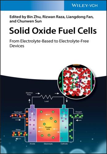
SolidOxideFuelCells
FromElectrolyte-BasedtoElectrolyte-FreeDevices
Editedby BinZhu RizwanRaza LiangdongFan ChunwenSun
Editors
BinZhu SoutheastUniversity SchoolofEnergyandEnvironment No.2SiPaiLou Nanjing210096 China
RizwanRaza COMSATSUniversityIslamabad CleanEnergyResearchLab(CERL) DepartmentofPhysics LahoreCampus Lahore54000 Pakistan
LiangdongFan ShenzhenUniversity CollegeofChemistryandEnvironmental Engineering DepartmentofNewEnergyScience andTechnology NanhaiAvenue3688 Guangdong Shenzhen518060 China
ChunwenSun
BeijingInstituteofNanoenergy andNanosystems ChineseAcademyofSciences No.30Xueyuanroad HaidianDistrict Beijing100083 China
CoverImages:SolidOxidefuelcell structure©Graphic_BKK1979/Getty Images,Electrolyte-freedeviceCourtesy ofProf.BinZhu,Background©Chad Baker/GettyImages
Allbookspublishedby Wiley-VCH arecarefullyproduced.Nevertheless, authors,editors,andpublisherdonot warranttheinformationcontainedin thesebooks,includingthisbook,to befreeoferrors.Readersareadvised tokeepinmindthatstatements,data, illustrations,proceduraldetailsorother itemsmayinadvertentlybeinaccurate.
LibraryofCongressCardNo.: appliedfor
BritishLibraryCataloguing-in-Publication Data
Acataloguerecordforthisbookis availablefromtheBritishLibrary.
Bibliographicinformationpublishedby theDeutscheNationalbibliothek TheDeutscheNationalbibliotheklists thispublicationintheDeutsche Nationalbibliografie;detailed bibliographicdataareavailableonthe Internetat <http://dnb.d-nb.de>
©2020Wiley-VCHVerlagGmbH& Co.KGaA,Boschstr.12,69469 Weinheim,Germany
Allrightsreserved(includingthoseof translationintootherlanguages).No partofthisbookmaybereproducedin anyform–byphotoprinting, microfilm,oranyothermeans–nor transmittedortranslatedintoa machinelanguagewithoutwritten permissionfromthepublishers. Registerednames,trademarks,etc.used inthisbook,evenwhennotspecifically markedassuch,arenottobe consideredunprotectedbylaw.
PrintISBN: 978-3-527-34411-6
ePDFISBN: 978-3-527-81278-3
ePubISBN: 978-3-527-81280-6
oBookISBN: 978-3-527-81279-0
Typesetting SPiGlobal,Chennai,India PrintingandBinding
Printedonacid-freepaper 10987654321
Contents
Preface xiii
PartISolidOxideFuelCellwithIonicConducting Electrolyte 1
1Introduction 3 BinZhuandPeterD.Lund
1.1AnIntroductiontothePrinciplesofFuelCells 3
1.2MaterialsandTechnologies 5
1.3NewElectrolyteDevelopmentsonLTSOFC 10
1.4BeyondtheStateoftheArt:TheElectrolyte-FreeFuelCell(EFFC) 20
1.4.1FundamentalIssues 23
1.5BeyondtheSOFC 25 References 28
2Solid-StateElectrolytesforSOFC 35 LiangdongFan
2.1Introduction 35
2.2Single-PhaseSOFCElectrolytes 37
2.2.1OxygenIonicConductingElectrolyte 37
2.2.1.1StabilizedZirconia 37
2.2.1.2DopedCeria 39
2.2.1.3SrO-andMgO-DopedLanthanumGallates(LSGM) 42
2.2.2Proton-ConductingElectrolyteandMixedIonicConducting Electrolyte 42
2.2.3AlternativeNewElectrolytesandResearchInterests 44
2.3IonConduction/TransportationinElectrolytes 49
2.4CompositeElectrolytes 52
2.4.1Oxide–OxideElectrolyte 52
2.4.2Oxide–CarbonateComposite 53
2.4.2.1MaterialsFabrication 54
2.4.2.2PerformanceandStabilityOptimization 57
2.4.3OtherOxide–SaltCompositeElectrolytes 60
2.4.4IonicConductionMechanismStudiesofCeria–Carbonate Composite 62
2.5NANOCOFCandMaterialDesignPrinciple 66
2.6ConcludingRemarks 67 Acknowledgments 69 References 69
3CathodesforSolidOxideFuelCell 79 TianminHe,QingjunZhou,andFangjunJin
3.1Introduction 79
3.2OverviewofCathodeReactionMechanism 80
3.3DevelopmentofCathodeMaterials 82
3.3.1PerovskiteCathodeMaterials 82
3.3.1.1Mn-BasedPerovskiteCathodes 83
3.3.1.2Co-BasedPerovskiteCathodes 85
3.3.1.3Fe-BasedPerovskiteCathodes 88
3.3.1.4Ni-BasedPerovskiteCathodes 89
3.3.2DoublePerovskiteCathodeMaterials 89
3.4MicrostructureOptimizationofCathodeMaterials 94
3.4.1NanostructuredCathodes 94
3.4.2CompositeCathodes 97
3.5Summary 102 References 103
4AnodesforSolidOxideFuelCell 113
ChunwenSun
4.1Introduction 113
4.2OverviewofAnodeReactionMechanism 114
4.2.1BasicOperatingPrinciplesofaSOFC 114
4.2.1.1TheAnodeThree-PhaseBoundary 115
4.3DevelopmentofAnodeMaterials 117
4.3.1Ni–YSZCermetAnodeMaterials 117
4.3.2AlternativeAnodeMaterials 118
4.3.2.1FluoriteAnodeMaterials 118
4.3.2.2PerovskiteAnodeMaterials 120
4.3.3Sulfur-TolerantAnodeMaterials 124
4.4DevelopmentofKinetics,ReactionMechanism,andModelofthe Anode 126
4.5SummaryandOutlook 135 Acknowledgments 137 References 137
5DesignandDevelopmentofSOFCStacks 145 WanbingGuan
5.1Introduction 145
5.2ChangeofCellOutputPerformanceUnder2DInterfaceContact 145
5.2.1Designof2DInterfaceContactMode 145
5.2.2VariationsofCellOutputPerformanceUnder2DContactMode 147
5.2.32DInterfaceStructureImprovementsandEnhancementofCell OutputPerformance 149
5.2.4Contributionsof3DContactin2DInterfaceContact 151
5.2.5MechanismofPerformanceEnhancementAftertheTransitionfrom 2Dto3DInterface 153
5.3ControlDesignofTransitionfrom2Dto3DInterfaceContactand TheirQuantitativeContributionDifferentiation 156
5.3.1ControlDesignof2Dand3DInterfaceContact 156
5.3.2QuantitativeEffectsof2DContactontheTransientOutput PerformanceofaCell 158
5.3.3QuantitativeEffectsof2DContactontheSteady-StateOutput PerformanceoftheCell 161
5.3.4QuantitativeEffectsof3DContactonCellTransient Performance 163
5.3.5QuantitativeEffectsof3DContactontheSteady-StatePerformanceof aCell 166
5.3.6DifferencesBetween2Dand3DInterfaceContacts 169
5.4Conclusions 171 References 172
PartIIElectrolyte-FreeFuelCells:Materials,Technologies, andWorkingPrinciples 173
6Electrolyte-FreeSOFCs:Materials,Technologies,andWorking Principles 175 BinZhu,LiangdongFan,Jung-SikKim,andPeterD.Lund
6.1ConceptoftheElectrolyte-FreeFuelCell 175
6.2SLFCUsingtheIonicConductor-basedElectrolyte 177
6.3DevelopmentsonAdvancedSLFC 179
6.4FromSLFCstoSemiconductor–IonicFuelCells(SIFCs) 184
6.5TheSLFCWorkingPrinciple 196
6.6Remarks 204 Acknowledgments 207 References 207
7CeriaFluoriteElectrolytesfromIonictoMixedElectronicand IonicMembranes 213
BaoyuanWang,LiangdongFan,YanyanLiu,andBinZhu
7.1Introduction 213
7.2DopedCeriaastheElectrolyteforIntermediateTemperature SOFCs 214
7.3SurfaceDopingforLowTemperatureSOFCs 216
7.4Non-dopedCeriaforAdvancedLowTemperatureSOFCs 222 References 235
8ChargeTransferinOxideSolidFuelCells 239 JingShiandSiningYun
8.1OxygenDiffusioninPerovskiteOxides 239
8.1.1OxygenVacancyFormation 239
8.1.2OxygenDiffusionMechanisms 242
8.1.3AnisotropyOxygenTransportinLayeredPerovskites 244
8.1.3.1OxygenTransportinRuddlesden–Popper(RP)Perovskites 244
8.1.3.2OxygenTransportinA-SiteOrderedDoublePerovskites 244
8.1.4OxygenIonDiffusionatGrainBoundary 246
8.1.5FactorsControllingOxygenMigrationBarriersinPerovskites 248
8.2ProtonDiffusioninPerovskite-TypeOxides 249
8.2.1ProtonDiffusionMechanisms 249
8.2.2Proton–DopantInteraction 253
8.2.2.1InfluenceofDopantsinA-site 253
8.2.2.2InfluenceofDopantsinB-Site 254
8.2.3Long-rangeProtonConductionPathwaysinPerovskites 255
8.2.4Hydrogen-InducedInsulation 256
8.3EnhancedIonConductivityinOxideHeterostructures 259
8.3.1EnhancedIonicConductionbyStrain 259
8.3.2EnhancedIonicConductivitybyBandBending 263
8.3.2.1SurfaceState-inducedBandBending 263
8.3.2.2BandBendinginp–nHeterojunctions 265
8.3.2.3p–nHeterojunctionStructuresinSOFC 265
8.4Summary 266 Acknowledgments 267 References 267
9MaterialDevelopmentII:NaturalMaterial-basedComposites forElectrolyteLayer-freeFuelCells 275 ChenXiaandYanyanLiu
9.1Introduction 275
9.1.1MaterialsDevelopmentforEFFCs 275
9.1.2NaturalMaterialsasPotentialElectrolytes 276
9.2Industrial-gradeRareEarthforEFFCs 279
9.2.1Rare-earthOxideLCP 280
9.2.2Semiconducting–IonicCompositeBasedonLCP 281
9.2.2.1LCP–LSCF 282
9.2.2.2LCP–ZnO 284
9.2.3StabilityOperationandSchottkyJunctionofEFFC 288
9.2.3.1PerformanceStability 288
9.2.3.2InSituSchottkyJunctionEffect 288
9.2.4Summary 290
9.3NaturalHematiteforEFFCs 291
9.3.1NaturalHematite 292
9.3.2Semiconducting–IonicCompositeBasedonHematite 295
9.3.2.1Hematite–LSCF 295
9.3.2.2Hematite/LCP–LSCF 297
9.3.3Summary 300
9.4NaturalCuFeOxideMineralsforEFFCs 302
9.4.1NaturalCuFe2 O4 MineralforEFFC 302
9.4.2NaturalDelafossiteCuFeO2 forEFFC 305
9.4.3Summary 308
9.5Bio-derivedCalciteforEFFC 308
9.5.1Bio-derivedCalciteforEFFC 309
9.5.2Summary 312 References 314
10ChargeTransfer,Transportation,andSimulation 319 MuhammadAfzal,MustafaAnwar,MuhammadI.Asghar,PeterD.Lund, NaveedJhamat,RizwanRaza,andBinZhu
10.1PhysicalAspects 319
10.2ElectrochemicalAspects 320
10.3IonicConductionEnhancementinHeterostructureComposites 321
10.4ChargeTransportationMechanismandCouplingEffects 326
10.5SurfaceandInterfacialState-InducedSuperionicConductionand Transportation 330
10.6IonicTransportNumberMeasurements 331
10.7DeterminationofElectronandIonicConductivitiesinEFFCs 332
10.8EISAnalysis 334
10.9SemiconductorBandEffectsontheIonicConductionDevice Performance 335
10.10Simulations 339 Acknowledgments 343 References 343
11Electrolyte-FreeFuelCell:PrinciplesandCrosslink Research 347 YanWu,LiangdongFan,NaveedMushtaq,BinZhu,MuhammadAfzal, MuhammadSajid,RizwanRaza,Jung-SikKim,Wen-FengLin,andPeterD. Lund
11.1Introduction 347
11.2FundamentalConsiderationsofFuelCellSemiconductor Electrochemistry 353
11.2.1PhysicsandElectrochemistryatInterfaces 353
11.2.2Electrochemistryvs.SemiconductorPhysics 355
11.3WorkingPrincipleofSemiconductor-BasedFuelCellsandCrossing LinkSciences 356
11.4ExtendingApplicationsbyCouplingDevices 367
11.5FinalRemarks 368 Acknowledgments 372 References 373
PartIIIFuelCells:FromTechnologytoApplications 377
12ScalingUpMaterialsandTechnologyforSLFC 379 KangYuan,ZhigangZhu,MuhammadAfzal,andBinZhu
12.1Single-LayerFuelCell(SLFC)EngineeringMaterials 379
12.2ScalingUpSingle-LayerFuelCellDevices:TapeCastingandHot Pressing 383
12.3ScalingUpSingle-LayerFuelCellDevices:ThermalSprayCoating Technology 386
12.3.1TraditionalPlasmaSprayCoatingTechnology 387
12.3.2NewDevelopedLow-PressurePlasmaSpray(LPPS)Coating Technology 388
12.4ShortStack 395
12.4.1SLFCCells 395
12.4.2BipolarPlateDesign 396
12.4.3SealingandSealant-FreeShortStack 396
12.5TestsandEvaluations 397
12.6DurabilityTesting 399
12.7ACaseStudyfortheCellDegradationMechanism 400
12.8ContinuousEffortsandFutureDevelopments 404
12.9ConcludingRemarks 409 References 411
13PlanarSOFCStackDesignandDevelopment 415 ShaorongWang,YixiangShi,NaveedMushtaq,andBinZhu
13.1InternalManifoldandExternalManifold 415
13.2InterfaceBetweenanInterconnectPlateandaSingleCell 416
13.3AntioxidationCoatingoftheInterconnectPlate 418
13.4DesigntheFlowFieldofInterconnectPlate 419
13.4.1MathematicalSimulation 420
13.4.2EffectofCo-flow,Crossflow,andCounterflow 422
13.4.3AirFlowDistributionBetweenLayersinaStack 424
13.5TheImportanceofSealing 424
13.5.1ThermalCyclingoftheSealing 428
13.5.2DurabilityofSealing 428
13.6TheLifeoftheStack:TheChemicalProblemsontheInterface 429
13.7TowardMarketProducts 431
13.8ConcludingRemarks 443 References 443
14EnergySystemIntegrationandFuturePerspectives 447 GhazanfarAbbas,MuhammadAliBabar,FidaHussain,andRizwanRaza
14.1SolarCellandFuelCell 447
14.2FuelCell–SolarCellIntegration 450
14.3SolarElectrolysis–FuelCellIntegration 452
14.4FuelCell–BiomassIntegration 453
14.5TheFuelCellSystemModelingUsingBiogas 454
14.5.1ActivationLoss 457
14.5.2OhmicLoss 457
14.5.3ConcentrationVoltageLoss 458
14.6TheFuelCellSystemEfficiency(HeatingandElectrical) 458
14.6.1TheEffectofDifferentTemperaturesonSystemEfficiency 458
14.6.2TheFuelUtilizationFactorandEfficienciesoftheSystem 458
14.6.3TheSystemEfficienciesandOperatingPressure 460
14.7IntegratedNewCleanEnergySystem 460
14.8Summary 462
References 462
Index 465
Preface
Thefuelcellisapromisingcleanenergytechnology,whichisnotyetfullycommercialized.Therearedifferenttypesoffuelcellsbasedonthechemicalreactionsandchargetransportationmechanismsemployed,butthesolidoxidefuel cell(SOFC)technologyexhibitsmajorpotentialforlarge-scaleapplications.This technologyis,however,stillsubjecttomaterialandtechnologychallengesaccompaniedwithhighcosts.ThoughtheliteratureontheSOFCtechnologyisample coveringvariousaspectssuchasmaterials,devices,electrochemistry,andapplications,thecontributionsonthelatestdiscoveriessuchasthenon-electrolyte fuelcellprinciplesarerare.
Thisbookisauniquecollectionofcontributionsonthedevelopmentofsolid oxidefuelcellsfromelectrolytebasedtonon-electrolyte-basedtechnology.Since thescientificdiscoveryofthefuelcellprinciplesome180yearsago,afuelcellhas beenconstructedwiththreebasiccomponents,namely,theanode,electrolyte, andcathode,ofwhichtheelectrolyteplaysakeyrolefortheoperationofafuel cell.Theelectrolyteservesseveralimportantrolessuchasiontransportation,and itsupportsthefuelcellredoxreactions(hydrogenoxidationontheanodeand oxygenreductiononthecathode).Butitalsoprovidesaseparatortoblockagainst electronspreventingthemtopassthroughthedeviceandforcingthemtomove throughanexternalcircuit,thuspreventingthefuelcellfromshort-circuiting. Thus,thequestion:howcouldafuelcelldeviceatallworkwithouttheconventionalelectrolytelayerishighlyjustified?
Thisbookaimsatgivingamorecomprehensiveunderstandingontheadvances infuelcellsandtobridgetheknowledgefromtraditionalSOFCtothenew concepts.WewilltrackthedevelopmentfromtheconventionalSOFCtothe non-electrolyte(layer)orsingle-componentfuelcell,coveringresearchon theanode,electrolyte,andcathodecomponentmaterials,anddevelopment ofdevicesandstacksforapplications.Akeyareaofunderlyingscienceof thebookdealswithsemiconductorandsemiconductor–ionicprinciplesfor non-electrolyte-basedfuelcells.
Thisbookisdividedintothreeparts.PartIisontheconventionalSOFC, providinganupdateonthelatestdevelopmentofanode,electrolyte,andcathode materialsaswellastheSOFCtechnologies.PartIIdiscussesthenon-electrolyte orsemiconductor-basedmembranefuelcells.Thisnewconceptfuelcell deviceshavebeendevelopedinrecentyearswithextensiveeffortsandbroad innovationsfrommaterials,technologies,devices,andscientificprinciplesby
crosslinkresearchfromsemiconductorphysicsandbandtheory.Thisnewtype SOFCshadbeendevelopedfromthesingle-layerfuelcells(SLFCs)orelectrolyte (layer)-freefuelcells(EFFCs)inthefirstinventionstowardsemiconductor andsemiconductor–ionicfuelcells.Westartwiththeconceptualproofofthis technologyemployingbothexistingSOFCstate-of-the-artmaterialsandthen introducingnewfunctionalsemiconductor–ionicmaterialstodemonstrate varioussingle-componentandsemiconductor–ionicfuelcelltechnologies withoutusingtheelectrolyteseparator.TheemphasisofPartIIisonvarious newsemiconductorsandsemiconductor–ionicmaterialsincludingthescientific principles,materials,deviceconcepts,andfuelcelltechnology.Semiconducting materialswithionicpropertiesandmobilityandthephysicsofsemiconductor energybandstructures,whichplayasignificantroleinasingle-component fuelcell.PartIIIofthebookfocusesonengineeringeffortsfrommaterials,technology,devicetostackdevelopments,andvariousapplicationsand newopportunitiesofSOFCusingboththeelectrolyteandnon-electrolyte technologies,includingintegratedfuelcellsystemswithelectrolysis,solar energy,etc.Twoimportantissueshavebeenseriouslyaddressedtoaccelerate SOFCcommercialization:(i)technicallytheinterfacesoftheplanarcelland stackand(ii)commerciallydesignedSOFCstackproductstomeetdemands ofcustomersandapplicableuses.Thenextcommercialpotentialofthese technologieswilldependontheiradvantagesanddisadvantages,butthenew semiconductor-basedmaterialsandtechnologiesexhibitquiteafewadvantages overtheconventionalelectrolyte-basedfuelcells.
Thoughthisbookusesaspecificfuelcelltechnology,thesolidoxidefuelcells, asbasisfordescribingadvancesinfuelcells,theintentionisalsotoprovidea strongervisioninfuelcellmaterialsandtechnologiesingeneral.Seriousandconcreteresearcheffortsarenecessarytostrengthenthisfieldandtoprovidenew pathsforinnovationsandbreakthroughthinkingonfuelcells.
Thebookwillserveasimportantreferenceworktostudents,researchers,and technologydevelopersinthefuelcellfield.Wehopethisbookwouldgivereaders freshideas,newknowledge,andinspiration.
10August2019
BinZhu,RizwanRaza,LiangdongFan, andChunwenSun (Editors) PeterD.Lund (Scientificadviser) StockholmandHelsinki
PartI
SolidOxideFuelCellwithIonicConductingElectrolyte
Introduction
BinZhu 1,* andPeterD.Lund 2,*
1 SoutheastUniversity,SchoolofEnergyandEnvironment,No.2SiPaiLou,Nanjing210096,China
2 AaltoUniversity,SchoolofScience,P.O.Box15100,Puumiehenkuja2,EspooFI-00076,Finland
1.1AnIntroductiontothePrinciplesofFuelCells
Fuelcellshavebeenunderdevelopmentformorethan180yearssinceits discoveryintheearlynineteenthcentury.Severaltypesoffuelcellshaveresulted fromextensiveresearchanddevelopmentwork,butonlytwotypeshavereached astageofcommercialization.Oneisthepolymerelectrolytemembranefuel cell(PEMFC)andtheotheristhesolidoxidefuelcell(SOFC).Itisagenerally acceptedopinionthattheformerisbetterapplicablefortransportationandthe latterforstationarypowerapplications.ThisbookfocusesonSOFCsranging fromtraditionalelectrolyte-basedtoelectrolyte-freeornon-electrolyte-based devices.Thefocusofcontentswillbeonmaterialsandtechnologies.
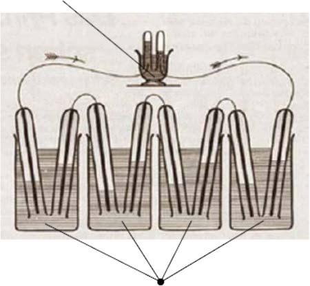
Goingbacktothehistoryoffuelcells,thefirstmajorstepindevelopmentwas thediscoveryofthewaterelectrolysistosplitwaterintohydrogenandoxygen usingelectricityatthebeginningofthenineteenthcentury.Electrolysisisactuallyareverseprocesstothefuelcell.Thefuelcellprinciplewasdiscoveredby HumphryDavyintheearlynineteenthcentury,whichwasfollowedbythepioneeringworkbyChristianFriedrichSchönbeinandSirWilliamGrovein1838, whorealizedthefuelcellconceptbyinventingthe“gasvoltaicbattery.”InGrove’s seriesofexperimentsonagasbatteryin1838/1839,anelectriccurrentcouldbe producedfromanelectrochemicalreactionbetweenhydrogenandoxygenover acatalystelectrodecouple[1].Figure1.1showsthefirstlaboratoryprototype deviceusingironandcoppersheetsashydrogenandoxygenredoxelectrodes (anodeandcathode),andasolutionofsulfateofcopperanddiluteacidasthe electrolyte.Thisisverysimilartoaphosphoricacidfuelcell.
Thetermfuelcellappearedinliteraturefirstin1889,whenresearchersdevelopedcoalgas,alsoreferredtofuelgas,andcoaldirectlyasafueltogenerate electricity.ThusGrove’sgasbatterywasnaturallynamedas“fuelbattery”and then“fuelcell.”Thefuelcell(FC)ismoresuitabletopresentGrove’sinvention,
*Correspondingauthors:Dr.BinZhu,binzhu@kth.se;Dr.PeterD.Lund,peter.lund@aalto.fi
SolidOxideFuelCells:FromElectrolyte-BasedtoElectrolyte-FreeDevices, FirstEdition.EditedbyBinZhu,RizwanRaza,LiangdongFan,andChunwenSun. ©2020Wiley-VCHVerlagGmbH&Co.KGaA.Published2020byWiley-VCHVerlagGmbH&Co.KGaA.
Figure1.1 SketchofWilliam Grove’s1839fuelcell,Grove’s 1839gasvoltaicbattery diagram.Source:Grove1839 [1].Reproducedwith permissionofTaylor& Francis.
whichalsoindicatesitscleardifferencefrombatteryenergystorageduetothe natureofconversion.Shortlysincedemonstratedin1839bySirGrove,allFCs havebeenconstructedwiththreefunctionalcomponents:anode,electrolyte,and cathode,togethercalledthemembraneelectrodeassembly(MEA).Inallcurrent FCtechnologies,theelectrolytehastobedensetopreventgaspermeability[2]. Theanodeandcathodeneedhydrogenandoxygencatalystsandsufficientionic andelectronicconductivitytocreatefuel(e.g.H2 )oxidationandoxidant(e.g. O2 )reductionprocesses.H+ orO2 ionsaresubsequentlytransportedthrough theelectrolytetoconvertthefuel’schemicalenergyintoelectricity,asshownin Figure1.2.
Phosphoric acid
Figure1.2 Classicalfivetypesofelectrolyte-baseddevicesinfuelcellfamily.
Thethree-componentMEAtechnologyrequiresacomplexFCstructureand technologyasallcomponentshavetobestableandcompatible.Theinterfaces betweenelectrolyteandanodeandcathode,respectively,contributetomajor polarizationlosses[3],whiletheFCdeliverspower,andacomplextechnology leadstohighcostsaswell,delayingFCcommercialization.Amongthethreecomponents,theelectrolyteisthekey[4].Itisoftencalledasamembranebecause afuelcelldeviceisanassemblybasedontheelectrolytemembrane,whichacts astheseparatorbetweentheanodeandcathodetoblockelectronicconduction toavoidelectronshort-circuitingproblem.Therefore,theelectrolyteisthepure ionicconductor,andanyelectronicconductioncanmakeelectrochemicalleakageleadingtolossesinthedevicevoltageandpoweroutput.Ontheotherhand, theelectrolytemusttransportionstosupportthefuelcellredoxreactions,i.e. hydrogenoxidationreaction(HOR)andoxygenreductionreaction(ORR).
SeveraltypesofFCshavebeendevelopedbasedonthetypeofelectrolytes, suchasPEMFCbasedonH+ transportinapolymerelectrolyte,AFC(alkaline fuelcell),OH ionsinasolution,PAFC(phosphoricacidfuelcell)withH+ in phosphoricacid,MCFC(moltencarbonatefuelcell)withCO= 3 inmoltencarbonates,andSOFCwithO2 inceramicoxides[4,5].Theelectrolytetypeandits electricalpropertiesdeterminewhichtypeofFCtechnologiesandfinalsystem canbeusedandwhichenergyconversionefficiencycanberealizedatacertain temperature.Figure1.2showsthesefivetypesofclassicalfuelcellsclassifiedby theelectrolyteused.
PAFC,MCFC,andAFChavebeenusedindifferentspecialapplications:e.g. kW-sizedAFCwasusedinApollo’smoonlandingprograminthe1960sand 1970swithsuccesstoproducebothpowerandwater.PAFCandMCFCwereprecommercializedinthelate1980s,andtherearestillongoingMCFCcommercial demonstrationplants,butthesetechnologiesneverreachedthescaleofcommercialization.OnlyPEMFCandSOFCareleftpushingtowardcommercialization.
1.2MaterialsandTechnologies
SOFCresearchanddevelopmentaredominatedbytheyttria-stabilizedzirconia (YSZ)electrolyte.In1899NernstfirstdiscoveredthatYSZcouldreachoxideion conductionataround1000 ∘ C(0.1Scm 1 ).Today,theYSZisstillthechoiceofthe electrolytematerialforhigh-temperatureSOFC.Atemperatureof800–1000 ∘ C istypicallyneededfortheYSZelectrolyteinordertoobtainasufficientlyhigh ionicconductivity[6,7],whichputsmajorconstraintstothechoiceofconstructionmaterialsandhasresultedinhighcosts,thusslowingthecommercialization forthelastdecades.Therehasbeenmuchefforttodevelopalternativeelectrolyte materialsforSOFCstolowertheoperatingtemperature[4,8,9].Examplesare fluorite-structuredion-dopedceria[10],perovskite-typeoxides[11],O2 conductingoxides[12],andprotonconductingceramics[13]aswellasothercomplexmaterialssuchasLa2 Mo2 O9 [14],BaIn-basedoxides[15],andapatite-type oxides[16].GoodenoughproposedthatSOFCshouldbedevelopedtowardlower enoughtemperaturestomakeittechnicallyuseful[17].Hisapproachwasto developoxideionconductorsbydesignfromstructuresbasedondiscovered
Figure1.3 Goodenoughproposedoxideionconductorbydesign:astructuralmethodby cationdopingtocreateoxygenvacancy.Source:Reproducedwithpermissionfrom Goodenough[17].Copyright2000,SpringerNature.
materials.Forexample,theYSZfluoritestructureispresentedinFigure1.3.By usingalowervalencycation,e.g.2+ or3+,toreplacehighervalentZr4+ ,some oxygenvacancymustbeproducedinordertomaintaintheelectricalneutrality inthecrystal.Inmostcases,trivalentY3+ ischosentoreplacetetravalentions, Zr4+ ,tocreatetheoxygenvacancysothatO2 canmovethroughvacanciesin theY-dopedzirconiastructure.
However,thisapproachisconstrainedbythestructureandtheobjectivehas notyetbeenrealized(tobediscussedlater).Usingmodernthinfilmtechnologies toreducethethicknessoftheYSZelectrolytefrommillimetertometer,toeven nanometerlevel,theelectrolyteresistanceandtheoperationaltemperature couldbereduced.Followingthis,strongdevelopmenteffortshavebeenmadeon employingvariousadvancedthinfilmtechnologiessuchassputtering,atomic layerdeposition(ALD),molecularextensiongrowth,laserdeposition,spark plasmasintering,andinsitusurfacenanoparticleexsolutionmethods,tofabricatethinfilmYSZ-basedelectrolyte.Forexample,Kosackipreparedathin(down to15nm)filmwithhighlytexturedYSZmembranethroughPLD(plasmalayer deposition)[18].Surprisingly,theconductivitiescouldbesignificantlyenhanced to0.6Scm 1 at800 ∘ Cwithsignificantlowactivationenergy(E a )of0.45eV.This conductivityisaboutoneorderofmagnitudehigherthanthatofaconventional YSZatthistemperature.ThebulkYSZreaches0.1Scm 1 ataround1000 ∘ C
O2– ion
Dopant Cation (2+ or 3+)
Host cation (4+) Vacancy
Current collector:
Cathode: LSC
Electrolyte: YSZ
Anode: NiO–YSZ
Substrate: LSTN–YSZ/STS
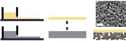
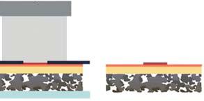
Figure1.4 Schematicsofthefabricationprocessofmicro-SOFCsupportedonLSTN–YSZ/STS substrate.(a)Tapecasting.(b)Lamination.(c)FiredsubstrateinH2 .(d)MEAdeposition.(e) Currentcollectordeposition.(f)Micro-SOFC.Source:Kimetal.2016[21].Reproducedwith permissionofSpringerNature.
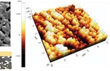
andactivationenergyisaround1.0eV.Thefirstdevelopmentofmicro-SOFCs (μSOFCs)usingthethinfilmYSZmembranesof50–150nmthicknesseswas successfullyfabricatedusingsputteringtechnologywiththePtelectrode.The devicedelivered60and130mWcm 2 at350and400 ∘ C,respectively[19].The pinhole-free,composition-controllable,andconformableelectrolytemembranes werefabricatedbyALDtechnology[20];thedeviceoperationaltemperature wasfurtherreducedto265 ∘ Cwhilemaintainingsufficientperformance.These pioneeringstudieshaveinturnstimulatedextensiveresearchonnanofilms for μSOFCs,bothfromfundamentalandappliedperspectives.Kimetal.[21] reportedsomedetailson μSOFCfabricationbyPLD(seeFigure1.4);achieving decentperformance,thepeakpowerdensitywas235,370,and560mWcm 2 at 450,500,and550 ∘ C.Figure1.5displaysitsmicrostructurewithacross-sectional viewofthedenseYSZaround1.5nminthickness.
Withlowtemperature(LT) <600 ∘ CSOFCdevelopmentsinadditionto reducingelectrolyteresistancebythinfilmtechnologies,anothercriticalissue arisesinvolvinginsufficientkineticprocessandcatalystfunctionleadingtoespeciallyslowerORRforthecathodereactionandpoweroutput.Thisisactually alimitingfactortodeterminethedeviceperformanceandefficiencyforlow temperatureoperations.Toovercomethesluggishkineticsfromtheelectrodes, especiallytominimizethecathodicpolarizationlossandenhancetheORR, toenablethedevicesufficientefficiencyandpoweroutput,mostresearchand developmenthavebeenfocusedonnewfunctionalcathodematerialstogether withmicrostructurecontrollinginthedevicefabrications.Variouseffectson themicrostructureincludethecomposition,particleandporesizesandtheir distributions,particleconnections,porosity,tortuosity,specificsurfacearea, ionicandelectronicconductivities,electrodethickness,andinterfacialbonding, whicharenotedforresearchanddevelopmentofanewcathodematerial,

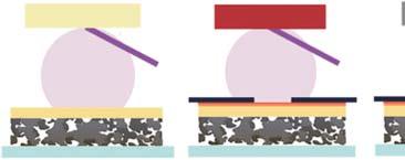
Figure1.5 Imageofmicro-SOFC.(a)SchematicofathinfilmMEAsupportedonporousSTS substrate.(b)Photographofacell.AlogoisatrademarkofPohangUniversityofScienceand Technology(POSTECH)andisprotectedbycopyright;itisusedinthisfigurewithpermission. Cross-sectionalSEMimageof(c)Pt/LSC/YSZ(Inset:magnifiedviewofPt/LSC),(d) YSZ/Ni-YSZ/LSTN-YSZ,and(e)LSTN-YSZcontactlayer.Source:Kimetal.2016[21].Reproduced withpermissionofSpringerNature.
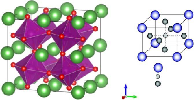
especiallybelow600 ∘ C[22,23].Perovskite-structuredoxides,ABO3 ,asshown inFigure1.6,havebeenusedsuccessfully[24].La(Mn/Co)O3 basedonA-site andB-sitedopingbyrareearth,alkalineearth,andtransitionelementsare successfulexamplesofhighperformance,moredurableandcomparablewith otherSOFCdevicecomponents.
A-cationsarelocatedineveryhole,whichiscreatedbyeightBO6octahedra, asshowninFigure1.6,thushavinga12-foldcoordinatesite,andtheB-cations in6-foldoxygencoordination.TherearemanyABO3 compoundsforwhich theidealcubicstructureisdistortedtoalowersymmetry(e.g.tetragonal, orthorhombic,etc.).Oxygenvacanciescanbecreatedbyionicdopingwithin theperovskitestructure,similarwithfluoritestructure.Iondopingeffect cancreateanimpactonbothelectronandiontransport.Oneofthebest perovskitecathodesforlow-temperaturesolidoxidefuelcells(LTSOFCs)is Ba0.2 Sr0.8 Co0.6 Fe0.4 O3 [25];itselectronicandoxygenionicconductivitiesat 600 ∘ Care200and0.1Scm 1 ,respectively.
Figure1.6 PerovskitestructureoxidesforfunctionalLTSOFCcathodecatalystmaterial.In ABO3 ,thereare(a)corner-sharing(BO6 )octahedrawithAionslocatedin12-coordinated intersticesand(b)B-sitecationatthecenterofthecell.Source:Kanetal.2016[24]. ReproducedwithpermissionofRoyalSocietyofChemistry.
Othertypesofperovskitestructureoxideshavebeenalsodevelopedfor LTSOFCs.Atypicalexampleisdoubleperovskites,Sr2 FeMoO6 (SFM)[26], becausetheunitcellistwicethatofperovskite.Ithasthesamearchitecture of12-coordinateAsitesand6-coordinateBsites,buttwocationsareordered ontheBsite.InthecaseofSr2 FeMoO6 ,theFeandMoatomsareorderedin a3Dchessboard-typefashion.Also,theratiobetweenFeandMocanmakea significanteffectonelectricalandcatalystfunctions.Typically,Sr2 Fe1.5 Mo0.5 O6 �� (SF1.5 M0.5 )hasbeenreportedforremarkableelectricalconductivityof550Scm 1 inairand310Scm 1 inhydrogenat780 ∘ C,asoneofthebestredoxstable electrodesforLTSOFCs;thismakesitavailableforbothanodeandcathode materialsinSOFCs.InthecaseofSFM0.5astheanodeandcathodetoconstruct asymmetricalSOFC,thedevicehasachievedapeakpowerdensityofover 835mWcm 2 at900 ∘ CusingH2 asfuelandambientairastheoxidant[26].
TheSFMshowsalsoagoodcatalystforoxidationofhydrocarbonfueloperation,e.g.directoxidationmethanolusingtheSFM0.5astheanodeandperovskite andBa0.5 Sr0.5 Co0.8 Fe0.2 O3 (BSCF)asthecathodebasedonperovskiteionicelectrolyte,La0.8 Sr0.2 Ga0.83 Mg0.17 O3 toconstructtheallperovskiteSOFCdevice, inaconfigurationofSF1.5 M0.5 /La0.8 Sr0.2 Ga0.83 Mg0.17 O3 (electrolyte)/BSCF.This deviceobtainedamaximumpowerdensityof391mWcm 2 at800 ∘ C[27].
Inadditiontoperovskitecathodes,othertransitionmetaloxidesarealsoefficientforlowtemperatureoperations,typicallynickeloxide,ironoxide,cobalt oxideandtheircomposites,orlithiatedoxides,suchaslithiatedorLicompound layerstructureoxides,suchasLix M(M = Ni,Fe,Co)O2 .Theseoxideshaveshown mucheffectivecatalystfunctionsduetoitsgreatprotonconductivity,sofarthe bestofprotonceramicmaterials,0.1Scm 1 at500 ∘ C[28],andotherunique advantages,e.g.triplechargecarriersofH+ ,O2 ande asshowninFigures1.7 and1.8[29,30].
Li xAl0.5Co0.5O2
Li x H yAl0.5Co0.5O2
Figure1.7 Layerstructurereportedhavingthehighestprotonconductivity0.1Scm 1 at 500 ∘ C.Source:ReproducedwithpermissionfromLanandTao[28].Copyright2014,John Wiley&Sons.
Pure e– conductor
Pure H+ conductor
Mixed O2–/e– conductor
Mixed H+/e– conductor H2O evolution point at triple phase boundary (TPB)
Ternary H+/O2–/e– conductor
H2O evolution point and line at double phase boundary (DPB) (a)(b) (d) (c)
Figure1.8 TriplechargetransferinLTSOFCcathodeandschematicillustrationsoftheoxygen reductionandwatergenerationpathwaysinvariouscathodes:(a)pureelectronicconductor; (b)mixedO2 /e conductor(mixedelectronicandionicconductor[MIEC],left)andMIEC compositedwithH+ conductingoxide(right);(c)mixedH+ andeconductor(mixedproton andelectronconductor[MPEC])and(d)triple-conducting(H+ /O2 /e )oxides.Source: ReproducedwithpermissionfromFanandSu[29].Copyright2016,Elsevier.
Figure1.8displaysthelayerstructureofLiNi0.8 Co0.2 O2 withatriple (H+ /O2 /e )conductingcatalystmaterial.Thetriplechargeconductingmaterial canspeedupthecathodicORRprocess,toreducesignificantlythecathodic polarization,thusenhancingthedeviceperformance.
1.3NewElectrolyteDevelopmentsonLTSOFC
AsproposedbyGoodenough,newmaterialsneedtobedevelopedtoreplace YSZ[19]tomakeSOFCoperationalatlowenoughtemperatures.Thismeans