RFIDandWirelessSensorsUsingUltra-Wideband Technology1stEditionAngelRamos
https://ebookmass.com/product/rfid-and-wireless-sensorsusing-ultra-wideband-technology-1st-edition-angel-ramos/
Instant digital products (PDF, ePub, MOBI) ready for you
Download now and discover formats that fit your needs...
Sensors and Probes for Bioimaging 1st Edition Young-Tae Chang
https://ebookmass.com/product/sensors-and-probes-for-bioimaging-1stedition-young-tae-chang/
ebookmass.com
Wideband Microwave Materials Characterization John W. Schultz
https://ebookmass.com/product/wideband-microwave-materialscharacterization-john-w-schultz/
ebookmass.com
Advising the Ultra-Wealthy: A Guide for Practitioners 1st ed. Edition Gregory Curtis
https://ebookmass.com/product/advising-the-ultra-wealthy-a-guide-forpractitioners-1st-ed-edition-gregory-curtis/
ebookmass.com
The Day Without Yesterday by John Farrell Desconocido
https://ebookmass.com/product/the-day-without-yesterday-by-johnfarrell-desconocido/
ebookmass.com
Brocklehurst’s Textbook of Geriatric Medicine and Gerontology 8th Edition Howard M. Fillit
https://ebookmass.com/product/brocklehursts-textbook-of-geriatricmedicine-and-gerontology-8th-edition-howard-m-fillit/
ebookmass.com
2019 novel coronavirus (2019-nCoV) outbreak: A new challenge Tommaso Lupia
https://ebookmass.com/product/2019-novel-coronavirus-2019-ncovoutbreak-a-new-challenge-tommaso-lupia/
ebookmass.com
Adobe Moon: Wyatt Earp: An American Odyssey Mark Warren
https://ebookmass.com/product/adobe-moon-wyatt-earp-an-americanodyssey-mark-warren/
ebookmass.com
Business of the Heart: Religion and Emotion in the Nineteenth Century John Corrigan
https://ebookmass.com/product/business-of-the-heart-religion-andemotion-in-the-nineteenth-century-john-corrigan/
ebookmass.com
Fundamental Things 1st
Edition
Louis Derosset
https://ebookmass.com/product/fundamental-things-1st-edition-louisderosset/
ebookmass.com
America’s Courts and the Criminal Justice System 13th Edition – Ebook PDF Version
https://ebookmass.com/product/americas-courts-and-the-criminaljustice-system-13th-edition-ebook-pdf-version/
ebookmass.com
RFID and Wireless Sensors using Ultra-Wideband Technology
Angel Ramos
Antonio Lazaro
David Girbau
Ramon Villarino
First published 2016 in Great Britain and the United States by ISTE Press Ltd and Elsevier Ltd
Apart from any fair dealing for the purposes of research or private study, or criticism or review, as permitted under the Copyright, Designs and Patents Act 1988, this publication may only be reproduced, stored or transmitted, in any form or by any means, with the prior permission in writing of the publishers, or in the case of reprographic reproduction in accordance with the terms and licenses issued by the CLA. Enquiries concerning reproduction outside these terms should be sent to the publishers at the undermentioned address:
ISTE Press Ltd
27-37 St George’s Road
Elsevier Ltd
The Boulevard, Langford Lane London SW19 4EU Kidlington, Oxford, OX5 1GB UK UK
www.iste.co.uk
www.elsevier.com
Notices
Knowledge and best practice in this field are constantly changing. As new research and experience broaden our understanding, changes in research methods, professional practices, or medical treatment may become necessary.
Practitioners and researchers must always rely on their own experience and knowledge in evaluating and using any information, methods, compounds, or experiments described herein. In using such information or methods they should be mindful of their own safety and the safety of others, including parties for whom they have a professional responsibility.
To the fullest extent of the law, neither the Publisher nor the authors, contributors, or editors, assume any liability for any injury and/or damage to persons or property as a matter of products liability, negligence or otherwise, or from any use or operation of any methods, products, instructions, or ideas contained in the material herein.
For information on all our publications visit our website at http://store.elsevier.com/
© ISTE Press Ltd 2016
The rights of Angel Ramos, Antonio Lazaro, David Girbau and Ramon Villarino to be identified as the authors of this work have been asserted by them in accordance with the Copyright, Designs and Patents Act 1988.
British Library Cataloguing-in-Publication Data
A CIP record for this book is available from the British Library Library of Congress Cataloging in Publication Data
A catalog record for this book is available from the Library of Congress
ISBN 978-1-78548-098-0
Printed and bound in the UK and US
Pre ace
Wireless sensor networks WSNs for smart cities, smart homes and Internet of Things IoT applications require low-power, low-cost and simple radio interfaces for a very large number of scattered sensors. UWB in time domain is used here as an enabling radio communications technology.
A comprehensive circuit model is explained for time-coded UWB RFID. Reader setups based on commercial impulse radars are combined with signal processing techniques. As a starting point, several chipless time-coded RFID tag designs are shown as examples. Then, the tags’ performance is shown in terms of a number of possible IDs, maximum reading distance, polarization, influence of attached materials, angular behavior and bending for tags on flexible substrates .
Chipless wireless sensors are derived based on these tag designs. Specifically, for temperature and concrete composition the latter enabled by permittivity sensing chipless sensors are shown as possible options.
In order to have more complex, more robust, and longer read range solutions, two chip-based semi-passive sensing platforms are inferred from the chipless tag designs. A wake-up link is used to save energy when the sensor is not being read.
Using an analog semi-passive UWB platform, a wireless temperature sensor powered by solar energy and a wireless nitrogen dioxide sensor enabled with carbon nanotubes and powered by a small battery are explained. Using a digital with a low-power microcontroller semi-passive UWB platform, a multi-sensor tag capable of measuring temperature, humidity, pressure and acceleration is analyzed.
In order to even further increase the read range, two active timecoded RFID systems are illustrated, based on the use of signal amplifiers within the tag.
Finally, a smart floor application for indoor localization is introduced, by joining the proposed designs with ground penetrating radar technology.
February 2016
Angel RA OS Antonio LA ARO
David GIRBAU, Ramon VILLARINO
Ac no ledgements
The authors would like to acknowledge the Spanish Government Projects TEC2008-06758-C02-02 and TEC2011-28357-C02-01, the Universitat Rovirai Virgili grant 2011BRDI-06-08, the AGAUR Grant FI-DGR 2012 and the 2020 Grant Agreement 645771 E ERGENT. The authors would also like to acknowledge the undergraduate students Sergi Rima, Xavier Domenech, Eduard Ibars and Cristian ernandez.
Introduction to RFID and hi less RFID
Automatic identification ID of goods is widely used in industry, logistics, medicine and other fields. The aim is to obtain the ID information of a good in transit. Giant electronic commerce platforms such as Amazon, Alibaba or eBay are becoming the main choice for buyers worldwide LOE 14 . Instead of buying from a small retailer, final customers are directly in contact with a wholesaler or distributor. In this context, accurate tracking of each good to its final customer is a major concern in a massive and growing logistics market. An efficient, automatic organization of the stock in large warehouses both sellers’ and logistics companies’ is also crucial to reduce costs and delivery times.
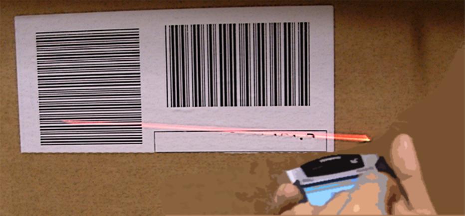
Nowadays, the barcode see Figure 1.1 is the most used automatic ID solution PAL 07 . It consists of a reader that optically reads a tag. The tag is created by printing black stripes on a white background. Depending on the number, width and separation of stripes, a unique ID is generated. In order to code more information in a smaller space, variations such as R codes DEN 14 have recently arisen. The cost of each barcode tag is extremely cheap because it only requires paper and ink. In addition, barcode readers are cheap, and even low-cost compact mobile phone cameras can provide high-resolution images to read barcodes O B 04 . owever, it requires a direct line of sight
between the reader and the tag. A specific positioning of the object is required in order to orientate the barcode toward the reader, and normally only one tag can be read at a time. Barcode storage capacity is also limited, and they cannot be reprogrammed. Another common problem with barcodes is misreading due to a low-resolution printing of the tag, or ink wearing away in harsh environments.
RFID state of the art
Introduction to RFID
In order to overcome barcode limitations, radio frequency identification RFID technologies have been developed in recent years FIN 10 . RFID systems are used to remotely retrieve data from target objects tags without the need for physical contact or line of sight by using magnetic or electromagnetic E waves. With some RFID systems, it is also possible to measure several tags at the same time and rewrite the tag information.
Figure 1.2 shows a basic scheme of an RFID system. There are two main families: near-field RFID Figure 1.2 a and far-field RFID
Figure 1.2 b WAN 06 . Near-field RFID is based on Faraday’s principle of magnetic induction magnetic coupling . Both the reader and the tag have coils. The reader powers up the tag’s transponder chip, which can be rewritten. Near-field RFID based on this inductive communication is used for small distances, typically below / 2 where is the wavelength WAN 06 . ISO 15693 and 14443 standards
Figure Photograph of a barcode system
Introduction to RFID and hi less RFID
set frequencies below 14 z, which results in a range of a few centimeters. Near-field RFID is widely used for cards and access control, but not for goods management due to its limited range. Far-field RFID uses E waves propagated through antennas both in the reader and the tag. A reader can be monostatic if it only has an antenna that acts for transmission Tx and reception Rx . On the contrary, if the reader has separate Tx and Rx antennas, it is bistatic. The reader sends an E wave that is captured by the tag’s antenna at a distance of several meters. There are several standards for far-field RFID, with the Electronic Product Code EPC Gen2 standard, at the Ultra igh Frequency U F 868 z in Europe or 915 z in the United States band, being the most used.
Figure Scheme of an RFID system; a) near-field and b) far-field
Even though the barcode is still the defacto standard, RFID is one of the fastest growing sectors of the radio technology. As of 2014, nearly every commercially available smartphone integrates near-field RFID with the Near Field Communication NFC forum’s standards AR 14 . Wal- art and Tesco, some of the largest retailers in the United States the and the United Kingdom, respectively, are adopting RFID WAN 06 . Furthermore, wireless ID has developed
into an interdisciplinary field. Radio frequency RF technology, semiconductor technology, data protection and cryptography, telecommunications and related areas come together to develop cheap, secure, reliable, long-range and self-powered RFID tags.
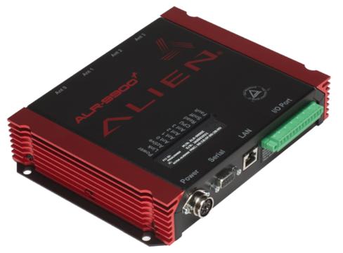
Far-field RFID systems can be classified depending on how the tags get the necessary energy to respond to the readers. Active tags are the most expensive tags, since they need their own power supply i.e. batteries not only to power their own chip but also to generate the radio signal with the response to the reader. Semi-passive tags are less expensive than active tags, since they need batteries, but only to power their own logic circuitry, not a transmitter. The response is achieved by changing the reflected signal from the reader in a process called backscattering. This means that the batteries can be smaller and have longer life times usually years . Finally, passive tags are the cheapest ones and have the largest commercial potential for largescale spreading VIT 05, COL 04 . Passive tags use the reader’s RF signal to harvest the necessary power for themselves VIT 05 . Specifically, passive U F EPC tags are the type of RFID tags most widely used for large-scale applications. Depending on the region, there are different frequency bands and maximum allowed powers allocated for RFID applications GS1 14 . In Europe, the most used band is 865.6 867.6 z, with a maximum transmitted power of 2 W of effective radiated power ERP , or, equivalently, 3.28 W of effective isotropic radiated power EIRP . Similarly, in the United States the allowed RFID band is 902 928 z, with a maximum transmitted power of 4 W EIRP, or, equivalently, 2.44 W of ERP. It can be observed that American regulations permit more transmitted power than European regulations, allowing for longer read ranges. ost manufacturers provide U F RFID tags and readers compatible with both European and American bands. Figure 1.3 shows an example of a typical commercial U F EPC Gen2 reader and tag from Alien Technology ALI 16 . These types of tags have a sensitivity of about 20 dBm I P 14, ALI 14 , and read ranges between 6 and 10 m depending on the region EXT 10 . Recent research has increased the read range to about 25 m by assisting the tag with a battery battery-assisted passive tags E 14 .
Introduction to RFID and hi less RFID
There have also been recent developments in millimeter wave bands. illimeter wave identification ID has been presented in PUR 08 as a concept of RFID operating at 60 G z. ID is not a replacement of RFID, since its read range is much shorter a few centimeters . ID, however, permits high data rate communications even gigabit . Directive antennas at millimeter wave frequencies are also very small compared to U F, permitting the possibility of selecting a tag by pointing toward it. The use of nonlinear devices for RFID tags has also been studied recently. Tags based on the inter-modulation distortion of devices have been presented in CAR 07 using a diode for localization applications, and in VII 09 using the micro electromechanical system.
Figure a) Alien ALR-9900 UHF EPC Gen2 RFID reader; b) Alien ALN9740 UHF RFID tag
Chipless RFID
Chipless tags are a specific type of passive RFID tags. In these tags, instead of storing the ID in a digital IC, it is stored in physical permanent modifications when the tag is fabricated. These modifications change from one tag to another. A notable reduction in costs for passive U F tags has been achieved recently VIT 05 due to the popularization in using RFID technology. owever, each U F tag price is fixed by the chip and by the process of connecting it to the tag antenna. Consequently, using chip-based tags is non-viable for identifying large volumes of paper or plastic documents such as banknotes, postage stamps, tickets or envelopes, since the price of the tag is larger than the document itself COL 04 . U F RFID technology also presents some weaknesses. U F frequency-band
allocation depends on the region, as well as the readers’ output signal power, which directly affects the read range the more power allowed, the longer the read distance . U F tags are affected by multipath propagation LA 09a , interference between readers LA 09b and frequency detuning due to different materials used as the tag physical support LOR 11 , factors that can lead to smaller read ranges. It is also necessary to consider special tags, used when attached to metal surfaces, which increase the total price.
baFigure a) Scheme of a chipless RFID system. b) Classification of chipless RFID tags [KAR 10]. For a color version of the figure, see www.iste.co.uk/ramos/rfid.zip
Chipless tags can be a promising low-cost alternative for RFID systems, since they do not need an IC to work KAR 10, TED 13 . In chipless tags, the ID is stored in physical permanent modifications in a scattering antenna. The modifications are unique for each tag, and change its RF backscattered response, or signature. Figure 1.4 a shows a scheme of a chipless RFID system. It is important to note that
Introduction to RFID and hi less RFID
chipless tags cannot change their information once they have been fabricated, since their physical characteristics are permanent. owever, chipless RFID can provide a low-cost alternative, which could increase the capabilities of barcodes. Since a standard for chipless RFID does not exist, there are several types of approaches undergoing active research to achieve chipless RFID tags. Figure 1.4 b shows a classification of chipless RFID tags given in KAR 10 . One drawback with chipless RFID tags compared with chip-based tags is the small number of possible IDs KAR 10, TED 13 . owever, this drawback is not very important if the chipless tag integrates additional capabilities beyond ID such as sensing.
Time-domain based time-coded tags encode the ID in the time delay of a reflected peak. Surface acoustic wave SAW technology offers a nonprintable alternative for chipless RFID AR 02, REI 98, REI 01 . SAW RFID is usually based on passive RFID systems, where the signal from the reader is converted into an acoustic wave. A scheme of a SAW tag is shown in Figure 1.5. The acoustic wave hits the tag substrate. Then, multiple reflections occurring at different time instants modify the wave. Then, it is reconverted to an RF signal and sent to the reader. These types of systems have great immunity to temperature changes, have high data transfer rates, can integrate sensors, and have a high read range AR 02 . owever, SAW tags are expensive and cannot be made easily due to their piezoelectric nature. Therefore, SAW chipless RFID cannot be used with low-cost products COL 04 . Thin film transistor circuit TFTC tags can be printed at high speeds on low-cost films DAS 06 . They are small in size and have low power consumption. owever, manufacturing TFTCs is not a low-cost process, and they are limited to several megahertz. Delay line-based chipless tags consist of an antenna followed by a delay line. Similar to SAW tags, delay line-based tags code the ID in reflections introduced by the delay line. Delay line-based tags can operate either at a narrowband S R 07 or wideband DOU 10 frequencies, but their ID capacity number of bits for a given tag size is small. owever, the read range of these types of tags is larger than frequency-coded or amplitude/phase backscatter modulation, as will be detailed next. Delay line-based chipless tags at wideband frequencies are studied in detail in this book.
Figure Scheme of a SAW tag. For a color version of the figure, see www.iste.co.uk/ramos/rfid.zip
Spectral signature based frequency-coded chipless tags encode the ID using resonant structures. Each bit state corresponds to a presence or absence of a resonance at a given frequency. Frequencycoded tags are printable, robust, have a moderate ID capacity and are low cost. owever, a large spectrum is often required in order to encode a large number of IDs, which may not be under regulation at all frequencies. Frequency-coded tags are more sensitive to orientation and distance than delay line based tags, and their read range is shorter. Chemical tags are designed from a deposition of resonating fibers or special electronic ink COL 06 . In COL 06 , tags fabricated from particles of chemicals that resonate at specific frequencies when illuminated by E waves are presented. Ink-tattoo chipless tags use electronic ink patterns printed on the surface of the object being tagged: no actual substrate is required ON 07 . Planar circuit frequency-coded chipless RFID has been the subject of research by several groups. In AL 05 , a tag consisting of an array of vertically polarized identical dipoles, capacitive tuned, is presented. Each dipole is tuned at different frequencies to code a data bit. In CV 06 , a frequency-coded tag based on space-filling curves at 900 z is presented. Space-filling curves can create resonances with very small footprints compared to the frequencies they are resonating. The main drawback with these types of tags is the difficulty in creating the appropriate layouts to achieve the required resonant frequencies. LC resonant chipless tags consist of a magnetic resonant coil at a particular frequency. Instead of working at a predetermined frequency, as with NFC standards, the reader sweeps a frequency band searching for a resonant frequency peak, which corresponds to the unique tag frequency ID . Commercial LC resonant chipless tags are widely
Introduction to RFID and hi less RFID
used for surveillance portals and antitheft purposes at supermarkets and retail stores FLE 02 . One interesting type of multi resonatorbased frequency-coded tag consists of a structure with two antennas in cross-polarization KAR 10 . The antennas are connected with a transmission line, loaded by resonators at different frequencies. The backscattered response codes the information in the presence or absence of the resonant peaks, determined by the resonators loading the transmission line in the tag. Finally, in TED 13 , another type of multi-resonant structure is presented. In this case, the structure is created by several dipoles that backscatter the incident wave in its orthogonal polarization. Each dipole is tuned at a predetermined frequency, and its presence or absence codes the corresponding bit state. The use of orthogonal polarization mitigates the clutter reflections and coupling between the reader’s antennas, allowing a better detection of the tags.
Amplitude-phase backscatter modulation-based chipless RFID tags operate at narrower bandwidths compared with time- or frequencycoded tags. These types of tags encode the ID varying the amplitude or phase of the backscattered signal due to the load connected to an antenna. Left-hand L delay line based tags consist of a narrowband antenna connected to a series of cascaded L delay lines SC 09 . Each L section produces a discontinuity in the phase of an incident wave. The reader interrogates the L -based tag using a modulated signal, such as quadrature phase shift keying. Each tag produces a unique phase variation on the carrier signal. Remote complex impedance-based chipless tags UK 07 are formed by a printable scattering antenna for instance a patch antenna loaded with a lossless reactance. Each tag has a unique reactance that generates a unique inductive loading. The backscattered signal thus has a different phase for each tag. Stub-loaded patch antenna based tags BAL 09a are similar to remote complex impedance-based tags, with increased robustness. In this case, a stub loads a patch antenna. The ID is coded in the cross-polarized phase difference between electric E and magnetic planes. Finally, carbon nanotube CNT loaded chipless tags consist of RFID antennas loaded by CNTs, which modify the scattering signature depending on their state. In AN 09 , a
conformal U F RFID antenna is loaded with single-walled CNTs to realize a chipless RFID gas sensor.
In summary, chipless RFID is a field of interest in RFID. There is not a common standard as in passive U F RFID. Therefore, chipless RFID is still the subject of active research. There are advantages and disadvantages between each approach, and the final application will decide which approach is chosen. ost of the published work on chipless RFID relies on using high-cost laboratory instruments as readers to demonstrate the feasibility of the proposed tags. owever, there is an increasing interest in developing custom readers TED 13 , which would reduce costs and enable the adoption of chipless RFID for specific market niches.
tending RFID ca abilities from ID to sensing
There have been many advances in the miniaturization and cost reduction of advanced sensors IC 08 . A large number of applications can benefit from the information about their environment these sensors can obtain. Smart homes EL 05 or smart cities EL 05 are concepts that have flourished recently. In both cases, one of the main ideas is to fill an area either houses or cities with small, self-autonomous and low-cost sensors. These sensors are connected creating so-called sensor networks IC 08 . For largescale applications, wiring each sensor is not viable. Also, some sensors can be placed in areas difficult to access. Therefore, wireless radio technologies that enable the sensors to be read remotely, creating a sensor node, are desired. The association of these wirelessly readable sensor nodes is called a wireless sensor network WSN . Apart from smart homes or smart cities, WSNs also have a great potential in a large number of applications such as IC 08 military target tracking and surveillance, natural disaster relief, biomedical health monitoring, hazardous environment exploration and seismic sensing. Low-power communication technologies are required to achieve years of lifetime for wireless sensors. Careful design for these technologies, based on small data rates for small amounts of information, only sensor readings , has to be taken into account.
Introduction to RFID and hi less RFID
Sensor nodes and readers or reading points RP can be associated in several ways. A direct wireless link between each sensor and RP see Figure 1.6 a , centralized star topology is a solution that requires high RF power transmitters if distances are long, with a consequent impact on battery lifetime or the need for a power supply to each sensor. A second possibility is to link the sensors in what is called a wireless network. In this way, the sensors also act as a bridge for other sensors see Figure 1.6 b , mesh topology . A third solution might be the use of a mobile link between sensors and RP see Figure 1.6 c , mobile topology . This means taking advantage of the mobility of vehicles inside a city, by using them to also transport information. For instance see Figure 1.6 d , buses can be good candidates. A bus always performs the same route, and stops periodically and repeatedly in bus stops. If a wireless sensor is installed in a bus stop and the reader at the bus, the sensor can be read every time the bus stops there. The information recorded in each trajectory can be downloaded at a point normally another bus stop , which is connected to the data management point. The main advantage of this solution is that lowpower consumption wireless sensors can be used, since read ranges are in the order of few meters,


Figure Sensors: green points. Reader point (RP): red point. a) Centralized topology, b) mesh topology, c) mobile RP topology and d) scheme of transmission between the bus and the bus station. For a color version of the figure, see www.iste.co.uk/ramos/rfid.zip
Existing technologies for WSNs
There are several commercial low-power solutions on the market for WSNs NAP 11, S I 11, GUN 09, TEX 14, DE 13 . Some of the most popular solutions are now compared in terms of cost, power consumption, speed and range. Table 1.1 summarizes typical values of these parameters for bluetooth low-energy LE , ANT and igBee technologies. Other technologies such as Wi-Fi IEEE 802.11 , NFC or infrared IrDA S I 11 were discarded in this comparison because they are not intended for wireless sensor applications either their power consumption is extremely high for miniaturized portable devices Wi-Fi or their read range is very short for a wireless sensor NFC or IrDA .
BluetoothLE: although its original aim was for mobile devices and accessories, the latest specification version 4.0 LE in 2010 takes into account low-power devices. Wearable devices, such as cardiac sensors or pedometers, companions for smartphones, are enabled with bluetooth LE WAN 13 .
ANT: a proprietary technology by Dynastream, working at 2.4 G z as bluetooth. It is aimed towards wearable devices in combination with smartphones D N 15 .
ZigBee: a specification given by the IEEE 802.15.4 standard, which is specifically intended for home automation and larger areas than bluetooth LE or ANT W E 07 .
Table Comparison between existing technologies for WSNs with typical values
Introduction to RFID and hi less RFID
As can be observed, bluetooth LE has very low average power consumption however, its peak current is very large for battery-less devices, which rely on external sources PAR 05 . These external sources can be the reader’s RF signal, solar energy or movement, for instance KI 13 . As introduced in section 1.1, passive RFID tags are powered from the reader’s signal.
RFID-enabled wireless sensors
The RFID reader uses a wireless communication link when it retrieves the ID from one or several tags. This link can also be exploited to collect data from a sensor connected to or embedded into the tag KI 13, WAN 04 . Adding sensing capabilities to RFID permits possibilities beyond what barcode systems offer. In addition, RFID systems have less complicated protocols and data frames than igBee or Bluetooth, for instance. Also, even though igBee or bluetooth can offer faster absolute data rates, the communication with RFID is established faster because the tag does not need to associate and authenticate with the reader at the beginning. One typical application for RFID-enabled wireless sensors is monitoring the cold chain in perishable products. The customer, as well as the seller and logistics companies, can determine the temperature range of the item from its production to its final destination. Accelerometers can also be used in fragile products in order to detect hits or bad package handling. As an example, in GON 14 , an RFID-enabled sensor tag is embedded in cork wine bottle stoppers to monitor their temperature.
RFID systems also have a several advantages for WSNs in smart homes or smart cities applications. The cost of RFID tags can be very low when using low-cost substrates and inkjet printing technology OL 03 . The architecture of RFID systems is also simpler than other systems such as bluetooth LE or igBee see section 1.2.1 , because the sensor tags do not require dedicated transceivers. It is also possible to integrate RFID systems in conventional WSNs, as shown in LIU 08 . RFID-enabled sensors are integrated with materials that are sensitive to physical parameters, for instance water-absorbing materials for humidity sensors and carbon nanostructures for gas sensors VEN 13a . The electrical parameters of the materials such as
RFID and Wireless Sensors Using Ultra-Wideband Technology
permittivity and conductivity are changed by the physical parameters. These electrical changes are translated in changes in the RFID signal. In the last few years, some platforms based on microcontrollers that emulate the behavior of passive U F EPC Gen2 tags have been presented. The best known example is the wireless ID and sensing platform SA 08 from Intel Research Seattle. A photograph is shown in Figure 1.7. Other similar platforms based on inkjet printing on paper substrates have been presented V K 09 .
Figure Photograph of the wireless identification and sensing platform (WISP) RFID-enabled sensing platform
Ultra- ideband technology for RFID a lications
Introduction to ultra-wideband technology
Ultra-wideband UWB radio technology uses very short nanosecond order time domain pulses FCC 03, OS 04 . Using these kinds of pulses widens the signal in the frequency domain to be much wider than traditional communications that use narrowband frequency-multiplexed signals. A UWB signal is defined as a signal with a bandwidth higher than 20 of its center frequency, or a signal with a bandwidth higher than 0.5 G z.
The American Federal Communications Commission FCC specified a band of operation for UWB signals from 3.1 to 10.6 G z in 2002 FCC 03 . This band can be used freely, with the only limitation of radiated power. Therefore, UWB signals cannot affect traditional narrowband communications. In Europe, the European Telecommunications Standard Institute ETSI and the European Conference of Postal and Telecommunications Administrations specified a slightly different power mask for UWB communications ETS 08, AST 09 . Figure 1.8 shows the maximum allowed indoor
Introduction to RFID and hi less RFID
and outdoor levels by both ETSI and FCC. Evidently, European regulations are more restrictive than American regulations. The FCC also allowed operation of UWB in 2002 while Europe did in 2005. Since the ETSI does not regulate a single country as the FCC does, approving the standard is slower and the final mask is more restrictive, to comply with all countries’ existing narrowband systems A 11 . From Figure 1.8, there is a band below 1 G z that is intended for ground penetrating radar GPR systems. GPR systems point the radar antenna s toward the ground floor, and therefore are not likely to cause interference on other systems DAN 05 . Figure 1.9 compares the transmitted power of a UWB signal and a narrowband signal as a function of frequency. It can be clearly seen that UWB signals require less power than narrowband signals, but their bandwidth is much higher than narrowband systems.
Figure Maximum indoor and outdoor levels of power spectral density (PSD) as a function of frequency for ETSI and FCC regulations. For a color version of the figure, see www.iste.co.uk/ramos/rfid.zip
Figure Comparison between power levels and frequency bandwidth of a narrowband and a UWB signal
Since UWB pulses have this large bandwidth, a UWB system permits better immunity to multipath propagation and narrowband interferences, because these kinds of interferences only affect a part of the complete spectrum. UWB also has good penetration in materials. Another advantage of UWB technology for RFID resides in the size of the antennas, which is usually smaller than traditional narrowband RFID due to the increase in the operating frequency. There exists rising demand for new antenna designs to have small dimensions. The higher frequencies of UWB enable compact hand readers and an increase in resolution position for localization systems. RF circuitry can be simpler with UWB, and data transfer rates can be higher. Therefore, an interest in UWB technology has arisen in industry and research fields FON 04 .
UWB-based RFID
UWB technology can be a promising solution for next-generation RFID systems due to the advantages inherent to its large bandwidth. any frequency bands from 9 k z to 24 G z are theoretically capable of being used in RFID. Some of these allocated bands are denominated industrial, scientific and medical IS , and they are usually free to use without any license in many countries. In front of the U F band for RFID, IS bands, especially the most popular one at 2.4 G z, is saturated because of wireless LAN and bluetooth applications, leading to a poor performance when using it for RFID. owever, UWB presents a frequency band that is much higher than allocated narrowband frequencies.
Additionally, even though IS bands do not need licenses, their emitting power is limited to avoid interferences, leading to a majority of active-only RFID tags in these bands, and the highest power consumption is precisely in the RF transmission part. UWB impulses need less power than narrowband signals, which means that UWB can be used to develop low-power active and semi-passive tags in the future. oreover, UWB is able to resolve the growing demand for higher data transmission speeds. The bandwidth with U F and IS bands is usually not sufficient for the resolution required in indoor localization applications. One of the most important commercial
Introduction to RFID and hi less RFID
applications of UWB and GPR is indoor localization due to their large bandwidth.
Despite all these potential advantages, it is still necessary to improve certain aspects such as cost reduction, tag tracking precision regardless of its speed or read rate and reading reliability. Recently, UWB-based chipless RFID systems have been proposed in the literature BAL 09b, A 06 . The number of IDs that chipless frequency-coded RFID can encode depends on the allowed bandwidth. Thus, the UWB is often used in these tags. In BAL 09b , chipless printable RFID tags are proposed by using several resonators in frequency domain. In SC 09, DOW 09 , sensors are integrated with chipless RFID tags to remotely read the sensor. In chipless passive RFID UWB tags, the read range is not limited by the power threshold to activate the chip, which is the main limitation for read distance of passive U F tags LA 09b .
oreover, multipath interferences can positively or negatively affect the read when working with U F RFID tags. The tag may not be readable even though it is inside the read range due to multipath LA 09b . This situation can be resolved using UWB technology, since different responses originated by the multipath interference can be minimized by using signal-windowing techniques in time domain.
An alternative method of using several resonators in the frequency domain consists of coding the information in the time delay DOU 10, DAR 08 . ere, the simplest way to code information is by varying the physical length of an open-ended transmission line connected to a scattering UWB antenna. The length of the transmission line changes the time delay of the reflection due to the tag antenna, and therefore different states can be coded. Although this idea has been proposed by some authors DOU 10, DAR 08 , there are few experimental results, which have been obtained by means of highcost instruments such as vector network analyzers. Future implementations of commercial readers should be based on low-cost equipment, such as impulse radio UWB radars.
rgani ation of this boo
The book is organized as follows. Chapter 2 describes the chipless time-coded UWB RFID theory, signal processing techniques and reader alternatives. Several designs of chipless tags are shown and characterized. A study and discussion on read range, resolution, number of bits, influence of angle, polarization, materials and tag bending are presented. Chapter 3 uses foundations and tags shown in Chapter 2 to design chipless sensors. Amplitude-based continuous and threshold temperature and delay-based permittivity for concrete composition detection chipless sensors are presented as examples. Chapter 4 describes semi-passive sensing platforms based on timecoded UWB RFID. Two topologies based on analog and digital approaches are explained. Chapter 5 integrates sensors in the semipassive sensing platforms from Chapter 4, and a temperature and a gas sensor this later based on CNTs are shown as examples. Chapter 6 shows a smart floor application where chipless Chapter 2 and semipassive Chapter 4 tags are combined with GPR techniques. Finally, Chapter 7 presents active long-range platforms based on time-coded UWB RFID intended for localization applications.
Introduction