& PRACTICAL Radiation Oncology Physics
A Companion to GUNDERSON TEPPER’S CLINICAL RADIATION ONCOLOGY
Sonja Dieterich, PhD, DABR
Associate Professor
Department of Radiation Oncology University of California Davis, California
Eric Ford, PhD, DABR
Associate Professor
Department of Radiation Oncology
University of Washington School of Medicine Seattle, Washington
Dan Pavord, MS, DABR
Chief Medical Physicist
Radiation Oncology
Health Quest Poughkeepsie, New York
Jing Zeng, MD, DABR
Assistant Professor
Department of Radiation Oncology
University of Washington School of Medicine
Seattle, Washington
1600 John F. Kennedy Blvd. Ste 1800 Philadelphia, PA 19103-2899
PRACTICAL RADIATION ONCOLOGY PHYSICS: A COMPANION TO GUNDERSON & TEPPER’S CLINICAL RADIATION ONCOLOGY
Copyright © 2016 by Elsevier, Inc. All rights reserved.
ISBN: 978-0-323-26209-5
No part of this publication may be reproduced or transmitted in any form or by any means, electronic or mechanical, including photocopying, recording, or any information storage and retrieval system, without permission in writing from the publisher. Details on how to seek permission, further information about the Publisher’s permissions policies and our arrangements with organizations such as the Copyright Clearance Center and the Copyright Licensing Agency, can be found at our website: www.elsevier.com/permissions
This book and the individual contributions contained in it are protected under copyright by the Publisher (other than as may be noted herein).
Notices
Knowledge and best practice in this field are constantly changing. As new research and experience broaden our understanding, changes in research methods, professional practices, or medical treatment may become necessary.
Practitioners and researchers must always rely on their own experience and knowledge in evaluating and using any information, methods, compounds, or experiments described herein. In using such information or methods they should be mindful of their own safety and the safety of others, including parties for whom they have a professional responsibility.
With respect to any drug or pharmaceutical products identified, readers are advised to check the most current information provided (i) on procedures featured or (ii) by the manufacturer of each product to be administered, to verify the recommended dose or formula, the method and duration of administration, and contraindications. It is the responsibility of practitioners, relying on their own experience and knowledge of their patients, to make diagnoses, to determine dosages and the best treatment for each individual patient, and to take all appropriate safety precautions.
To the fullest extent of the law, neither the Publisher nor the authors, contributors, or editors, assume any liability for any injury and/or damage to persons or property as a matter of products liability, negligence or otherwise, or from any use or operation of any methods, products, instructions, or ideas contained in the material herein.
Library of Congress Cataloging-in-Publication Data
Dieterich, Sonja, author.
Practical radiation oncology physics: a companion to Gunderson & Tepper’s Clinical radiation oncology / Sonja Dieterich, Eric Ford, Daniel Pavord, Jing Zeng. p. ; cm.
Per publisher’s web site, this book is a companion to the fourth edition of Clinical radiation oncology, by Drs. Leonard Gunderson and Joel Tepper.
ISBN 978-0-323-26209-5 (pbk. : alk. paper)
I. Ford, Eric (Radiation oncologist), author. II. Pavord, Daniel, author. III. Zeng, Jing (Radiation oncologist), author. IV Clinical radiation oncology (Gunderson). 4th ed. Supplement to (expression): V Title.
[DNLM: 1. Radiation Oncology. 2. Physics. QZ 269]
RC270.3.R33
616.99′40757—dc23
Senior Content Strategist: Suzanne Toppy
Senior Content Development Specialist: Dee Simpson
Publishing Services Manager: Hemamalini Rajendrababu
Senior Project Manager: Beula Christopher
Design Manager: Amy Buxton
Illustrations Manager: Karen Giacomucci
Marketing Manager: Deborah Davis
Printed in China Last digit is the print number: 9 8 7 6 5 4 3 2 1
2015013608
Reference Dosimetry for Ionizing Radiation
1.1 Introduction
The key to the accurate delivery of radiation is the ability to establish the absolute dose delivered. In radiation therapy clinical practice the primary tool used to measure absorbed dose is the ion chamber. The use of ion chambers has been well described by international codes of practice. While some of the details may differ slightly, the basic concepts of the various codes of practice are the same. The ionization measured by the chamber (typically filled with air) is converted to absorbed dose by applying a calibration factor (determined by an accredited calibration lab) and other correction factors based on the chamber design. The calibration factor may be a direct calibration in water (megavoltage (MV) photons, MV electrons, protons) or a calibration based on air kerma (kilovoltage (kV) photons, brachytherapy sources). The end goal is to determine absorbed dose to water in either case.
The starting point for these calibrations is the absorbed dose standard developed at a primary standard dosimetry laboratory (PSDL). End users obtain a calibration factor for their equipment at a secondary standard dosimetry laboratory (SSDL), also known as an accredited dosimetry calibration lab (ADCL). The SSDL applies the standard developed by the PSDL using the available radiation sources at that lab. All SSDLs have 60Co sources available for calibration but may not have linac-generated beams. Some labs do have other high energy photon beams available and can provide a calibration at multiple beam qualities. In the absence of this, correction factors must be applied to the calibration determined at 60Co energy to determine the calibration for the beam quality of interest. Further corrections are needed if the beam of interest is protons or other heavy ions. For a more complete discussion of the interaction between PSDLs, SSDLs, and the end user, the reader is referred to section 2.1 of International Atomic Energy Agency (IAEA) TRS-398, Absorbed Dose Determination in External Beam Radiotherapy: An International Code of Practice for Dosimetry Based on Standards of Absorbed Dose to Water.1
The regulations on the frequency of a full calibration in water may vary from country to country but are generally required at least once per year. The suggested regulations by the Conference of Radiation Control Program Directors (CRCPD) and implemented by many states in the United States require full calibrations at intervals not to exceed 12 months (section X.7.iii). More frequent constancy checks are required but can be done using solid phantoms and dosimetry equipment that is not calibrated by a calibration laboratory. These constancy devices should be compared with the calibrated system immediately after the annual full calibration. The equipment used for the full calibration should be sent for recalibration every 2 years. A constancy check should be performed before sending equipment to the calibration lab and after receiving it back to ensure that nothing happened during the process to change the response of the chamber. For new radiation therapy treatment machines, a second check of the absolute dose calibration should be obtained prior to treating patients.2 This could be accomplished by using
a mail-order reference dosimetry service or a second check by a colleague using an independent dosimetry system.
1.2 Standard Megavoltage Photon Beams
Several international codes of practice are used to determine absorbed dose for MV photon beams, the American Association of Physicists in Medicine (AAPM) TG-51, Protocol for Clinical Reference Dosimetry of High-Energy Photon and Electron Beams,3 IAEA TRS-398, Absorbed Dose Determination in External Beam Radiotherapy,1 Deutsche Industrie-Norm (DIN) 6800-2, Dosimetry Method for Photon and Electron Radiation—Part 2 Dosimetry of High Energy Photon and Electron Radiation with Ionization Chambers,4 Institute of Physics and Engineering in Medicine (IPEM) 1990, Code of Practice for High-Energy Photon Therapy Dosimetry,5 and others. An addendum to AAPM TG-51 has been published containing new kQ values.6 They are all based on absorbed dose in water calibrations of cylindrical ion chambers. The charge reading obtained from the ion chamber is corrected for temperature, pressure, ion recombination, and polarity. Corrections are then made to account for the perturbation to the medium (water) caused by the presence of the ion chamber. The calibration factor is then used to convert charge to absorbed dose. All of the protocols use a reference field size of 10 cm × 10 cm but the depth and source-to-surface distance (SSD) can vary among them. It is important to note that the reference depth for the calibration protocol is likely not the depth of absorbed dose specification in the clinic. For example, the protocol may specify measurement at 10 cm depth but the output of the machine is adjusted to 1.0 cGy/MU at depth of dose maximum (dmax). This will require the use of accurate percent depth dose to correct the readings taken at 10 cm depth to dmax depth. The general equation to calculate absorbed dose from a charge reading of an ion chamber measured with an electrometer is:
DzMNkkkkz wD,wpsQ ()() = ρ
where D w(z) = absorbed dose to water at depth z
M = the ion chamber reading corrected for the electrometer calibration
ND,w = calibration factor for absorbed dose to water for 60Co energy
kp = polarity correction. The value is generally less than 1% from unity. The value should be stable from year to year and any deviation greater than 0.5% from the running average should be investigated. For new chambers, it should be measured several times to establish consistency.
ks = ion recombination factor. The value is generally less than 1.01 and AAPM TG-51 recommends not using a chamber if the correction is greater than 5%. The same recommendation regarding year-to-year stability applies.
k
ρ = air density correction factor (often formulated as a temperature/pressure correction)
kQ(z) = beam quality correction factor for the measured beam versus the 60Co beam (in which Nw is determined). kQ is specific to the beam energy being measured and the ion chamber used to make the measurement. Typical values range from 1 to approximately 0.96 for MV photon beams.
A comparison of the four codes of practice is shown in Tables 1.1 to 1.5. Comparisons among the codes of practice show variations within the expected uncertainty levels of 1% to 1.5%.8-10 Standards labs are moving toward offering calibrations at beam qualities other than 60Co. This has the advantage that the kQ factor determined will be for the specific chamber used in the clinic, not a generic kQ for a given chamber model. There are two possibilities for implementing this strategy:
TABLE 1.1 ■ Polarity Correction (kp) Determination for the Various Protocols
DIN 6800-2 ()[()] MM/M/MM/M Co 121121 + +
IPEM 1990 none
When determining polarity corrections and comparing among systems, care should be taken to understand the bias configuration used. This can vary among manufacturers. The value can either be less than or greater than 1 depending on which polarity is used for the final output determination but should not exceed 1%. In general kp is a smaller effect with increasing energy. It should be noted that if kp is known for the calibration beam quality (Q0), kp will then be determined as kp = kp,Q/kpQ0. It follows from this that if the user beam quality (Q) is the same as the calibration beam quality (Q0), kp = 1. This must be done if kp exceeds 0.3% for 6 MV or 60Co energies.
TABLE 1.2 ■ Ion Recombination (ks) Determination for the Various Protocols for Pulsed Beams
AAPM TG-51 1 VV MMVV HL HL HL / rawraw// IAEA TRS-398
DIN 6800-2
IPEM 1990
1+X% for an X% decrease in reading when chamber voltage is halved
Since MMHLrawraw > , the value is always >1. It should be noted that ion recombination is mostly dependent on dose per pulse and therefore will be different for flattening filter free beams.7
TABLE 1.3 ■ kρ Determination for the Various Protocols
AAPM TG-51 2732 2732220 10133 . .. . + + × T P where T = water temperature in °C and P = pressure in kPa. Humidity must be between 20% and 80%.
IAEA TRS-398
DIN 6800-2
IPEM 1990
Standard temperature is 20 instead of 22. Therefore the denominator is 273.2 + 20.0 in the temperature term.
1. The calibration lab determines ND,w for the chamber along with a series of kQ values across the range of beam qualities including electrons. This has the advantage that because the beam energy dependence for the chamber is not expected to change, future calibrations will only require determination of ND,w at the reference quality, Q 0
2. The calibration lab determines a series of ND,w values, eliminating the need for kQ
TABLE 1.4 ■ Photon Beam Quality Correction Factors for the Various Protocols
AAPM TG-51
IAEA TRS-398
Table of values for various ion chambers across a range of beam energies. Beam quality is specified by the percent depth dose (PDD) at 10 cm depth, 100 cm SSD with electron contamination removed or PDD(10)x for energies ≥10 MV. To measure the photon component PDD, a thin lead foil (1 mm) is placed at 50 cm from the source to eliminate electron contamination from the beam at energies of 10 MV or greater. This lead foil is used for measurement of the PDD only and must be removed for the output measurement.
Table of values for various ion chambers across a range of beam energies. Beam quality is specified by the ratio of the TPR at 20 cm depth and the TPR at 10 cm depth for the reference field size or TPR20,10. This can be measured directly or calculated from PDD measurements using the equation 1.2661* (PDD(20)/ PDD(10)) 0.0595. Recommend using a measured value rather than a generic value.
DIN 6800-2
Same as IAEA.
IPEM 1990 Beam quality is specified by the ratio of the TPR at 20 cm depth and the TPR at 10 cm depth for the reference field size or TPR20,10
TABLE 1.5 ■ Ion Chamber Location for the Various Protocols
AAPM TG-51 Reference point (center of chamber) at measurement depth.
IAEA TRS-398 Reference point at measurement depth.
DIN 6800-2
Reference point 0.5 r below measurement depth. DIN 6800-2 also explicitly uses a perturbation correction to account for the difference in chamber position at the calibration lab (reference point at measurement depth) and the local dose measurement. Factor = 1 + |δ| r/2, where δ is the relative gradient of the depth dose curve at the point of measurement (about 0.006 mm 1 for 60Co) and r is the inner radius of the chamber.
IPEM 1990 Reference point at measurement depth.
1.3 Nonstandard Megavoltage Photon Beams
There are photon delivery machines that cannot produce the required 10 × 10 cm reference field and/or the SSD required by the codes of practice, including TomoTherapy, CyberKnife, Gamma Knife, and Vero. Furthermore, the geometry of some treatment units such as Gamma Knife do not readily accommodate the use of water phantoms for primary dose calibration, and so an air/ medium protocol such as AAPM TG-21, A Protocol for the Determination of Absorbed Dose from High Energy Photon and Electron Beams, is sometimes used.11 The forthcoming AAPM TG-178, Gamma Stereotactic Radiosurgery Dosimetry and Quality Assurance, will address the topic of dose calibration of stereotactic radiosurgery beams for Gamma Knife. Some beams are not compliant with standard protocols because they do not have a flat dose profile (e.g., TomoTherapy or flattening filter free beams), which complicates reference dosimetry.12
In addition, the size of the detector must be appropriate for the beam. The detector size should be small enough so that the gradient across detector volume is less than a few percent. Kawachi et al. showed that the relatively flat portion of the beam for a CyberKnife cone does not exceed 1 cm, as shown in Figure 1.1 13 The gradient can be caused by the inherent gradient created by beams without flattening filters. References are available that describe the additional corrections that must be made for these units to accurately calculate absorbed dose. The corrections are made by adjusting the value of kQ to account for the lack of charged particle equilibrium.
Figure 1.1 A comparison of the 1% flat widths at 10 cm of depth in water between the CyberKnife and an ordinary 6 MV linac (Clinac 21EX, Varian, ME). The SCD is 80 cm for the CyberKnife and 100 cm for the linac. (Adapted from Kawachi T, Saitoh H, Inoue M, et al. Reference dosimetry condition and beam quality correction factor for CyberKnife beam. Med Phys 2008;35(10):4591.)
The correction is about 1% for a TomoTherapy unit14 to as much as 10% for small cones on a CyberKnife unit.13 For flattening filter free beams there may be a slight correction needed for the quality factor if the Tissue-Phantom Ratio (TPR) 20 10 is used to specify beam quality.12 There are several treatment machines either in early clinical use or in development that use MR imaging. Ion chamber readings will need a correction factor that may depend on the magnetic field strength.15,16
1.4 Megavoltage Electron Beams
The measurement of absorbed dose for megavoltage electrons is similar to that of megavoltage photon beams. AAPM TG-51 and AAPM TG-70, Recommendations for Clinical Electron Beam Dosimetry, describe the methodology in detail. AAPM TG-70 is a supplement to AAPM TG-25, Clinical Electron Beam Dosimetry, and describes many clinical issues related to electron beams in addition to reference dosimetry.17,18 Again the primary reference dosimeter is an ion chamber. For electrons, however, parallel plate ion chambers can be used and are in fact recommended for lower energy electron beams. AAPM TG-51 requires a parallel plate chamber for ≤6 MeV and recommends using one for <10 MeV beams. IAEA TRS-398 and DIN 6800-2 recommend parallel plate chambers for all energies but allow cylindrical chambers for beams with R50 > 4 cm in water. The same corrections are applied for air density, polarity, recombination, and electrometer calibration as for megavoltage photon beams. If a cylindrical ion chamber is used an additional gradient correction factor, PQgr, must be measured and included.
Beam quality is specified by the depth of the 50% depth dose in water. If a cylindrical ion chamber is used to measure the depth dose, the curve must be shifted upstream by 0.5 rcav to account for the effective point of measurement, and the resulting depth ionization curve must be converted to depth dose by using stopping power ratios. AAPM, IAEA, and DIN all specify the same equations to convert depth ionization to depth dose at the depth of 50% ionization:
RIcmforIcminwater 505050102800610=∗−
RIcmforIcminwater 505050105903710=∗−
It is also possible to derive R50 more directly from a measurement with a diode, which does not require the shift or stopping power corrections described for ion chambers.
The reference depth for all of the protocols is calculated as 0.6 R50 – 0.1 (cm). The absorbed dose at dmax is then determined using the measured percent depth dose.
If using a parallel plate chamber without a calibration factor from a standards lab, the calibration factor can be obtained through cross calibration with a calibrated cylindrical chamber. The cross calibration should be performed using a high energy electron beam. Details are given in AAPM TG-51 in section X.C and in TRS-398 in section 7.6.1.
1.5 Kilovoltage Photon Beams
Beams in the kV range may be handled differently, depending on the actual beam energy and on the protocol. Superficial, orthovoltage, and electronic brachytherapy units are included in this section.
AAPM TG-61, AAPM Protocol for 40-300 kV X-ray Beam Dosimetry in Radiotherapy and Radiobiology,19 and IAEA TRS-3981 describe the methodology used to measure absorbed dose for kV photon beams. AAPM TG-61 is based on an air kerma calibration of an ion chamber. It covers the range from 40 kV to 300 kV. Either parallel plate or cylindrical chambers can be used for beams >70 kV, with the effective point of measurement being the center of the air cavity. A parallel plate chamber with a thin entrance window must be used for beams <70 kV. Thin plastic plates may be needed to remove electron contamination and provide adequate build-up. For beams <100 kV the measurement must be made in air, and a backscatter factor used to account for phantom scatter. A table of backscatter values based on SSD and beam quality is given. Beam quality is based on half value layer (HVL) in Al or Cu. Beams >100 kV are measured in water at a reference depth of 2 cm.
Corrections for ion recombination, polarity, electrometer calibration, and air density are made as described in Section 1.2. In addition, corrections for timer end effect and chamber stem effect are made. The beam quality correction factors for kV beams in IAEA TRS-398 uses an absorbed dose to water methodology. Because absorbed dose in water calibrations is not readily available at standards labs, the calibration factor is usually calculated from an air kerma calibration factor. This is described in Appendix A.2 of IAEA TRS-398. TRS-398 has a section for low energy kV and medium energy kV beams. For low energy kV beams a parallel plate chamber is recommended. The reference point is the outer surface of the parallel plate chamber or the outer surface of the plastic plates if they are used to ensure adequate build-up. Because the reference point is at the outer surface of the chamber (or plates) and must be flush with the phantom surface, plastic phantoms are recommended due to the difficulty of doing this in a water phantom. HVL is used as the beam quality index, although there is discussion that this is not entirely accurate and introduces up to about 1.5% uncertainty. For medium energy kV beams a cylindrical chamber with a volume between 0.1 and 1.0 cm 3 must be used. The reference point is at the center of the volume and should be placed at 2 cm depth in water.
Both AAPM TG-61 and IAEA TRS-398 recommend that the calibration be obtained by matching kV and HVL of the clinical beam if possible. If not possible, then multiple calibration points should be obtained and the clinical calibration factor is then determined by interpolation. The method of interpolation (ln based) is described in the absorbed dose calculation worksheet. A comparison of kV dosimetry protocols showed good agreement, with the exception of the IPEM and AAPM TG-61 protocols at 120 kV where differences on the order of 5% to 7% were seen.20 The differences may be due to the accuracy of the backscatter factors used or use of HVL as the sole beam quality specification.
1.6 Brachytherapy Sources
Brachytherapy sources are generally calibrated using an air-filled well chamber. AAPM TG-43, Dosimetry of Interstitial Brachytherapy Sources, and the following updates21-23 describe a general
method to calculate absorbed dose at any point from an air kerma strength value, Sk, which has units of µGy m2 hr 1, which is given the symbol U. The well chamber is calibrated in terms of this air kerma strength by obtaining a calibration factor to convert the current reading from the well chamber to air kerma strength from an ADCL.
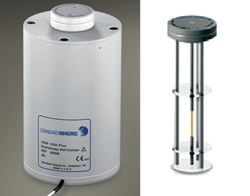
The well chamber can either be open to the air or pressurized to increase the signal of the chamber. If a pressurized well chamber is used, it is very important to perform constancy measurements to ensure that there has not been a leak in the chamber. The response of the well chamber is dependent on the position of the source within the well. A source holder is used to reproducibly position the source in the center of the well. For low dose rate (LDR) seeds the source is simply dropped into the holder, which is designed to position the seed at the area of uniform response. If possible, there should be a visual indication that the seed is in the correct position to ensure reproducibility. Figure 1.2 shows a typical well chamber and source holder. For high dose rate (HDR) remote afterloading systems the source is usually stepped through the length of the well by inserting a thin catheter connected to the HDR unit into the holder to find the position of maximum reading. This position should be consistent from measurement to measurement, but the stepping process ensures that the correct reading is obtained. Figure 1.3 shows a typical well chamber response versus source position. The point of maximum reading is generally referred to as the “sweet spot”. It should be noted that usually the LDR seed holder is different from the HDR holder. In either case, the holder used in the clinic must be sent with the well chamber when it is calibrated so that the exact conditions can be repeated in the clinic. For low energy sources such as 125I or 103Pd, the calibration must be obtained for the specific model of seed used clinically. This is due to the fact that the energy spectrum is greatly affected by the seed construction. For higher energy sources such as 192Ir, a generic value can be used.24 The IPEM has published a protocol for 192Ir using reference air kerma rate (RAKR).25 The RAKR is given as Gy s 1 at 1 m. A conversion to air kerma strength is given so that it can be compared with AAPM TG-43 formalism.
When calibrating an 192Ir source, the well chamber should be 1 m from any wall or scattering material and placed on a plastic cart. The well chamber should be left in the room for sufficient time to allow for thermal equilibrium, which could be up to 7 hours for a 4 °C temperature difference using a Standard Imaging HDR 1000 Plus well chamber. It has been shown that the well chamber reading can change by as much as 1.1% as it is moved toward a scattering surface and that without the Styrofoam insert thermal changes can be 0.15%.26 The protocol also mentions that a source geometry factor may be included in the future that would account for different source models. This factor is currently assumed to be unity. Air density, ion recombination, and
Figure 1.2 A typical well chamber and source holder.
Relative reading
Dwell position distance (cm) WELL CHAMBER RESPONSE vs. SOURCE POSITION
Meter reading (nA)
Figure 1-3 Sample well chamber response versus source position for an 192Ir HDR source.
electrometer calibration corrections are applied. This protocol and AAPM TG-56, Code of Practice for Brachytherapy Physics,27 recommend the use of a tertiary system to confirm the constancy of the secondary system used for the calibration. This can either be another well chamber or a farmer chamber placed in a jig at 10 cm distance. There is also an older AAPM Report, TG-41, Remote Afterloading Technology, that describes HDR source calibrations.28 A useful review of international protocols for 192Ir HDR sources has been published by Azhari et al.29 Calibration of sterilized seeds for interstitial implants presents a challenge to the clinical user. The AAPM TG-56 has recommended that at least 10% or 10 sources, whichever is greater, must be assayed by the on-site physicist for loose seeds.30 For stranded products the recommendation is 5% or 5 seeds, whichever is fewer. To meet this requirement, extra sources from the same batch may be ordered for calibration purposes, which will increase the cost. Alternatively, the calibration seeds could be ordered nonsterile and then assayed on site and resterilized. In addition, methods for calibrating the seeds while maintaining sterility have been proposed.31,32
When calibrating a brachytherapy source, a comparison is made to the manufacturer’s calibration certificate. AAPM TG-56 recommends that the values should match within 3%. Deviations between 3% and 5% should be investigated. Having a tertiary dosimetry system will aid in this investigation and is recommended as mentioned previously. Differences greater than 5% should be reported to the manufacturer. If the source is part of a batch to be used for seed implantation, the mean of the batch should agree with the manufacturer’s calibration within 3% and all sources should be within 5% of the mean.
1.7 Proton Radiotherapy Beams
IAEA TRS-3981 describes the determination of absorbed dose in proton beams. Parallel plate chambers can be used for all beam energies, but cylindrical chambers can be used only for beam qualities at reference depth Rres > 0.5 g cm 2. Cylindrical chambers are preferred when appropriate. Rres is the residual range and is defined as the distance from the center of the spread out Bragg peak (SOBP) to the distal 10% depth. Rres is used as the beam quality index in the protocol and is determined from depth dose measurements made with a parallel plate chamber. The depth ionization is converted to depth dose by applying stopping power ratios. If Pion and Ppol vary with depth, these corrections should also be used. The reference point for the absorbed dose
measurement is the center of the SOBP. One of the factors affecting accuracy is the ripple in the SOBP, which should be <±3%. The protocol has tables for the values of kQ,Q0 which are all calculated values with Q 0 equal to 60Co. Air density, ion recombination, and polarity corrections are used when calculating the absorbed dose. For small fields that are less than twice the diameter of the parallel plate chamber air cavity, a more suitable dosimeter such as a diode or microchamber should be used. It must be validated against the parallel plate chamber at a larger field size.
1.8 Potential Errors in Reference Dosimetry
The Radiological Physics Center (RPC; now called IROC-Houston) published a report describing common errors encountered when switching to AAPM TG-51.33 These included incorrect use of parallel plate chambers, mixing of phantom materials, inconsistent use of depth dose factors to transfer dose to dmax, incorrect use of the lead foil used to measure PDD(10)X, incorrect chamber shifts, and the use of outdated stopping power data. In addition, an error of approximately 5% could be introduced if the lead foil required for determination of PDD(10)X is not removed before measuring absorbed dose. Polarity and ion recombination effects vary with depth and should be measured at the reference depth. TRS-3981 makes many references to the errors introduced by using non-water phantoms (with the exception of low energy kV beams). There have been several instances of large calibration errors made due to using an inappropriately large chamber for small fields. Examples include a stereotactic radiosurgery beam at a facility in Springfield, MO, commissioned with a detector that was too large, which resulted in 76 patients receiving an overdose of 50% from 2004 to 2009.34 In these instances, the chamber appropriate for the calibration of the standard field (10 × 10) was also used when determining the absolute dose for add-on devices such as a stereotactic cone or multi-leaf collimator (MLC).
1.9 Dosimetric Uncertainties
Accurate reference dosimetry is the key to delivering accurate doses in Radiation Oncology, and this is vitally important because an error will affect every patient treated with the beam in question. Use of incorrect equipment or procedure has led to multiple reports of clinical misadministration of radiation therapy to patients. Many times in this book we refer to the goal of achieving ≤5% combined error in dose delivery. To achieve this, the reference dosimetry must contribute a small uncertainty because there are also other contributing factors to the 5% combined error. Dosimetry protocols should be adhered to and measurements should be documented. Best practice is to perform absolute dose calibration measurements in water on a yearly basis with reference dosimetry equipment that receives an outside calibration. Before treating patients, calibration should be audited with an independent measurement.
When reviewing an annual calibration report, multiple factors contribute to the measurement uncertainty. Typical values are shown in Table 1.6 for external beam therapy.
A similar analysis for brachytherapy sources was performed by AAPM TG-138, A Dosimetric Uncertainty Analysis for Photon-Emitting Brachytherapy Sources.35 They concluded that the determination of air kerma strength has an overall uncertainty of less than 3%. Table 1.7 shows the different sources of uncertainty and their magnitude. It should be noted that this uncertainty applies only to the determination of air kerma strength. Uncertainties in the determination of AAPM TG-43 dosimetric parameters and delivery issues are not included.
It is instructive to read the explanation of uncertainties given by the calibration lab in their report. This provides an idea of the types and magnitudes of uncertainties in the calibration process. Along with the calibration factor itself, the greatest sources of errors can come from the determination of the beam quality correction factor and the electrometer reading.
TABLE 1.6
■ Impact of Various Uncertainties in External Beam Reference Dosimetry36
Electrometer reading Meter reproducibility, stability, linearity, and leakage
Beam quality correction factor
Measurement reproducibility, different methodologies for measurement
Ion recombination correction factor Measurement reproducibility, different methodologies for measurement
Polarity correction factor Measurement reproducibility, different methodologies for measurement
TABLE 1.7 ■ Estimated Uncertainty in the Calibration of Air Kerma Strength
Measurement Description
FOR THE PHYSICIAN
The initial reference dosimetry of a radiation source, either external beam or brachytherapy, must be performed with a high degree of accuracy because an error at this step will affect every patient treated with that source. To standardize this dosimetry, various professional societies, government agencies, and international agencies have established protocols for determining the absolute absorbed dose for the types of radiation sources used in Radiation Oncology.
At the core of a dosimetry protocol is the establishment of a dose standard at a primary standard dose laboratory. The dosimetry equipment used in a clinic is sent to a secondary standard dosimetry laboratory to obtain a calibration factor. This is repeated at a minimum of 2-year intervals to ensure that the response of the equipment remains unchanged.
For megavoltage photon and electron beams there are many national calibration protocols as well as an international protocol. Comparisons among the various protocols have shown agreement on the order of 1% to 1.5%. They all use the common methodology of converting the charge collected by an air-filled ion chamber in a water phantom to absorbed dose to water for a reference field, 10 cm × 10 cm. Various corrections to account for air density, chamber response, and perturbation of the radiation beam due to the replacement of the medium (water) by the ion chamber are applied to the charge reading. The corrected reading is then multiplied by the calibration factor to obtain the absorbed dose. There are several units that cannot produce the standard
reference field, and special corrections are needed in those cases (e.g., TomoTherapy, CyberKnife, Gamma Knife, and Vero).
Low energy kilovoltage beams have the maximum dose at or very near the surface, and the measurements can be made in air instead of water. The chamber is calibrated in air at the standards laboratory, and corrections are applied to convert to dose in water. Kilovoltage beams can have very different beam spectra even for beams with the same accelerating potential. Because of this, calibration should be made by matching the accelerating potential and half-value layer of the beam as closely as possible. It may be necessary to obtain multiple calibration points and then interpolate to obtain the calibration factor for the clinical beam.
Brachytherapy sources are calibrated using a well chamber. The calibration factor from the standards laboratory converts the current reading from the well chamber to air kerma strength. Sources that are delivered in sterile packaging for interstitial implants present a particular challenge. Either a method to calibrate the seeds while maintaining sterility must be developed or an appropriate number of nonsterile seeds from the same batch can be ordered for calibration purposes.
For any radiation source, the reference dosimetry protocol should be well understood to minimize the chance for errors. Errors of 50% or more have been reported, with severe consequences to the patients. To further minimize the potential for error, reference dosimetry should be carefully reviewed by another physicist prior to clinical use; in the case of a new external beam unit, the reference dosimetry should be verified using a remote dosimetry service or peer review.
References
1. IAEA TRS-398 (V.11b), Absorbed dose determination in external beam radiotherapy: An international code of practice for dosimetry based on standards of absorbed dose to water. Vienna: The International Atomic Energy Agency; 2004.
2. ASTRO. Safety is no accident. 2012. p. 34. https://www.astro.org/uploadedFiles/Main_Site/Clinical_ Practice/Patient_Safety/Blue_Book/SafetyisnoAccident.pdf.
3. Almond PR, Biggs PJ, Coursey BM, et al. AAPM’s TG-51 protocol for clinical reference dosimetry of high-energy photon and electron beams. Med Phys 1999;26(9):1847–70.
4. DIN 6800-2, Dosimetry method for photon and electron radiation: Part 2, Dosimetry of high energy photon and electron radiation with ionization chambers. National Standard Dosimetry Protocol, Germany, 2008.
5. Lillicrap SC, Owen B, Williams JR, et al. Code of practice for high-energy photon therapy dosimetry based on the NPL absorbed dose calibration service. Phys Med Biol 1990;35(10):1355–60.
6. McEwen M, DeWerd L, Ibbott G, et al. Addendum to the AAPM TG-51 protocol for clinical reference dosimetry of high-energy photon beams. Med Phys 2014;41:041501-1-20.
7. Lang S, Hrbacek J, Leong A, et al. Ion-recombination correction for different ionization chambers in high dose rate flattening filter free photon beams. Phys Med Bio 2012;57:2819–27.
8. Zakaria A, Schuette W, Younan C. Reference dosimetry according to the new German protocol DIN 6800-2 and comparison with IAEA TRS-398 and AAPM TG-51. Biomed Imaging Interv J 2011;7(2):e15.
9. Castrillon SV, Henriquez FC. Comparison of IPSM 1990 photon dosimetry code of practice with IAEA TRS-398 and AAPM TG-51. JACMP 2009;10(1):136–46.
10. Zakaria A, Schuette W, Younan C. Determination of absorbed dose to water for high-energy photon and electron beams—comparison of the standards DIN 6800-2 (1997), IAEA TRS-398 (2000) and DIN 6800-2 (2006). J Med Phys 2007;32(1):3–11.
11. McDonald D, Yount C, Koch N, et al. Calibration of the Gamma Knife Perfexion using AAPM TG-21 and the solid water Leksell dosimetry phantom. Med Phys 2011;38(3):1685–93.
12. Xiong G, Rogers DW. Relationship between %dd(10)x and stopping power ratios for flattening filter free accelerators: A Monte Carlo study. Med Phys 2008;35(5):2104–9.
13. Kawachi T, Saitoh H, Inoue M, et al. Reference dosimetry condition and beam quality correction factor for CyberKnife beam. Med Phys 2008;35(10):4591.
14. D uane S, Palmans H, Sephton J, et al. Alanine and ion chamber dosimetry in helical TomoTherapy. Radiother Oncol 2006;81:S45.
15. Reynolds M, Fallone BG, Rathee S. Dose response of selected ion chambers in applied homogeneous transverse longitudinal magnetic fields. Med Phys 2013;40(4):042102-1-7.
16. Meijsing I, Raaymakers BW, Raaijmakers AJE, et al. Dosimetry for the MRI accelerator: The impact of a magnetic field on the response of a Farmer NE2571 ionization chamber. Phys Med Biol 2009; 54(10):2993–3002.
17. Gerbi BJ, Antolak JA, Deibel FC, et al. Recommendations for clinical electron beam dosimetry: Supplement to the recommendations of Task Group 25. Med Phys 2009;36(7):3239–78.
18. Khan FM, Doppke KP, Hogstrom KR, et al. Clinical electron beam dosimetry: Report of AAPM radiation therapy committee task group 25. Med Phys 1991;18:79–103.
19. Ma C-M, Coffey CW, DeWerd LA, et al. AAPM protocol for 40-300 kV x-ray beam dosimetry in radiotherapy and radiobiology. Med Phys 2001;28(6):868–93.
20. Munck PM, Nilsson P, Knöös T. Kilovoltage x-ray dosimetry—an experimental comparison between different dosimetry protocols. Phys Med Biol 2008;53(16):4431–42.
21. Rasmussen BE, Davis SD, Schmidt CT, et al. Comparison of air-kerma strength determinations for HDR 192Ir sources. Med Phys 2011;38(12):6721–9.
22. Nath R, Anderson LL, Luxton G, et al. Dosimetry of interstitial brachytherapy sources: Recommendations of the AAPM radiation therapy committee Task Group No. 43. Med Phys 1995;22:209–34.
23. Rivard MJ, Coursey BM, DeWerd LA, et al. Update of AAPM Task Group No. 43 Report: A revised AAPM protocol for brachytherapy dose calculations. Med Phys 2004;31(3):633–74.
24. Rivard MJ, Butler WM, DeWerd LA, et al. Supplement to the 2004 update of the AAPM Task Group No. 43 report. Med Phys 2007;34(6):2187–205.
25. Bidmead AM, Sander T, Locks SM, et al. The IPEM code of practice for determination of the reference air kerma rate for HDR 192Ir brachytherapy sources based on the NPL air kerma standard. Phys Med Bio 2010;55:3145–59.
26. Podgorsak MB, DeWerd LA, Thomadsen BR, et al. Thermal and scatter effects on the radiation sensitivity of well chambers used for high dose rate 192Ir calibrations. Med Phys 1992;19(5):1311–14.
27. Nath R, Anderson LL, Meli JA, et al. Code of practice for brachytherapy physics: Report of the AAPM radiation therapy committee task group No. 56. Med Phys 1997;24(10):1557–98.
28. Glasgow GP, Bourland JD, Grigsby PW, et al. AAPM Report No. 41, remote afterloading technology. New York, NY: The American Association of Physicists in Medicine; 1993.
29. Azhari HA, Hensley F, Schütte W, et al. Dosimetric verification of source strength for HDR afterloading units with 192Ir and 60Co photon sources: Comparison of three different international protocols. J Med Phys 2012;4:183–92.
30. Butler WM, Bice WS Jr, DeWerd LA, et al. Third-party brachytherapy source calibrations and physicist responsibilities: Report of the AAPM low energy brachytherapy source calibration working group. Med Phys 2008;35(9):3860–5.
31. Otani Y, Yamada T, Kato S, et al. Source strength assay of iodine-125 seeds sealed within sterile packaging. JACMP 2013;14(2):253–63.
32. Butler WM, Dorsey AT, Nelson KR, et al. Quality assurance calibration of 125I rapid strand in a sterile environment. Int J Radiat Oncol Biol Phys 1998;41(1):217–22.
33. Tailor RC, Hanson WF, Ibbott GS, et al. AAPM TG-51: Experience from 150 institutions, common errors, and helpful hints. JACMP 2003;4(2):102–11.
34. Bogdanich W, Ruiz RR. Radiation errors reported in Missouri. New York Times 2010. Available from: http://www.nytimes.com/2010/02/25/us/25radiation.html.
35. DeWerd LA, Ibbott GS, Meigooni AS, et al. A dosimetric uncertainty analysis for photon-emitting brachytherapy sources: Report of AAPM Task Group No. 138 and GEC-ESTRO. Med Phys 2011; 38(2):782–801.
36. Castro P, García-Vicente F, Minguez C, et al. Study of the uncertainty in the determination of the absorbed dose to water during external beam radiotherapy calibration. JACMP 2008;9(1):70–86.
Relative Dosimetry for MV Beams
2.1 Introduction
Since the basic physics of dosimetry for radiation beams is extensively covered in textbooks on radiotherapy physics, this chapter will focus on the measurement of dosimetry data in clinical practice. There are two main goals in measuring relative dosimetry data: (1) confirming the accurate technical functionality of the accelerator to produce a symmetric beam of correct energy and known relative output as specified at acceptance testing and (2) characterizing the available beams of a specific treatment device for input in treatment planning software (TPS).
(1) ACCURATE TECHNICAL FUNCTIONALITY
Relative dosimetry is very sensitive to technical changes in the accelerator itself. For example, changes in the steering coils or ion chamber can cause the beam symmetry to deviate above the limits specified by acceptance testing and American Association of Physicists in Medicine (AAPM) recommendations. Relative dosimetry is used during installation and acceptance testing to fine-tune accelerator technical parameters. Subsequently, relative dosimetry measurements are used as part of periodic accelerator QA to verify accurate and consistent functioning of the accelerator. AAPM Task Groups (TG)-401 and TG-1422 provide detailed tables of the relative dosimetry measurements, frequencies, and tolerances recommended for clinical practice in standard linear accelerators. AAPM TG-1353 and TG-1484 provide additional information for CyberKnife and TomoTherapy, respectively.
(2) CHARACTERIZING BEAMS FOR TPS
Measurements of relative dosimetry data during commissioning are used as input in TPS and secondary monitor unit (MU) calculation. It is therefore essential for the data to be of high quality, because they provide the basis for treating thousands of patients during the lifetime of the treatment delivery machine. The relative dosimetry data set taken during annual QA serves two purposes. First, it is a more stringent check on accelerator technical performance than the monthly or daily relative dosimetry measurements. Second, the annual dosimetry data are used to confirm that the machine is still accurately characterized by the data set used in the TPS. Therefore, it is important to use the baseline TPS data after commissioning as the basis for comparison. For example, if a measured value was originally 2% different from the TPS value and changed to 3.5% different in subsequent years, a comparison to measurement baseline would show only a 1.5% difference, which occludes the actual mismatch between TPS and beam data.
Vendors of TPS generally do provide a list of required relative dosimetry measurements for TPS commissioning. There are several main approaches to commissioning TPS:
1. The TPS requires a set of relative dosimetry data to be measured and entered by the user. Some of these types of TPS do provide standard beam data sets for delivery machines for comparison purposes but use the measured data set for treatment planning. An example for this approach is the CyberKnife MultiPlan TPS.
2. The TPS is delivered with a standard data set for a delivery machine. The measured relative dosimetry data set could be used for verification that the machine is “sufficiently matched” to the standard data set to be used for treatment planning. An example of this approach is the Varian Eclipse TPS. There are currently no manufacturer-independent recommendations on the tolerance for the measured versus standard data set match. While this use of pre-existing beam data is not in agreement with the recommendations of AAPM TG-1065, it follows established clinical practice for TomoTherapy and Gamma Knife (see item 4 below). If this approach is taken, the vendor-provided data must be very carefully compared against measured data and any deviations thoroughly assessed.
3. The relative dosimetry measurement data are used to generate parameters for one or more beam models. Examples of this approach are the Philips Pinnacle, Elekta XIO, and RaySearch RayStation planning systems. Modeling beam sizes from 40 cm × 40 cm maximum down to small fields of 0.5 cm × 0.5 cm size with one parameter set may require compromise on model accuracy that may not be acceptable in clinical practice. In those cases, it may be prudent to generate two beam models for one beam energy to match the relative dosimetry across all field sizes.
4. The TPS is part of a treatment delivery system and comes precommissioned from the manufacturer. The relative dosimetry measurements are used only to verify the manufacturergenerated data. An example for this approach is the TomoTherapy system and Leksell Gamma Knife.
The rapid development of technology has had an impact on the requirements for relative dosimetry measurements as well. Accelerator dose rates have increased by a factor of 10 or more due to improvements in accelerator design and the adoption of flattening filter free (FFF) beam delivery across almost all delivery systems. The introduction of intensity-modulated radiation therapy (IMRT) and volumetric modulated arc treatment (VMAT) has heightened the importance of accurate penumbra dosimetry measurements to correctly model steep dose gradients at the field edge in the TPS. Improvements in multi-leaf collimator (MLC) design have reduced the leaf width to 2.5 mm in some cases, allowing the treatment of targets as small as 5 mm using the rule of thumb of 2× the minimum leaf width. This development requires the use of smallfield relative dosimetry techniques, which previously were restricted to dedicated stereotactic radiosurgery/stereotactic body radiotherapy (SRS/SBRT) devices. The increased use of SRS, SBRT, and hypofractionated treatment regimens has increased the demands on relative dosimetry accuracy, because the impact on systematic errors introduced by uncertainties in relative dosimetry on clinical plan delivery accuracy is increased compared to conventional fractionation schemes.6,7 The Institute of Physics and Engineering in Medicine (IPEM) report on small field dosimetry8 provides a very comprehensive introduction to relative dosimetry in small megavoltage (MV) photon beams. In this chapter, we follow the nomenclature of AAPM TG-1065 to define “small field” as any field equal to or less than 4 cm × 4 cm equivalent square. “Very small field” denotes fields equal to or smaller than 2 cm × 2 cm equivalent square. Chapter 4 deals in more depth with the topic of commissioning and QA of new treatment equipment (a TPS being one of them). Standard references are AAPM TG-539 (QA for Clinical Radiotherapy Equipment) and International Atomic Energy Agency (IAEA) Report 430 (Commissioning and QA of Computerized Planning Systems).
2.2 Commissioning Equipment
WATER TANK
Acquiring a good quality set of relative dosimetry data requires the appropriate equipment. The largest single piece of equipment is the water phantom, which should have the following features:
■ Size appropriate to measure the largest required field, plus several centimeters of additional depth/width to create backscatter at the edges of the field
■ A phantom stand allowing alignment of the tank itself
■ 2D or 3D motion axes that can be adjusted such that the detector moves parallel to the water surface
■ An automated central axis (CAX) function to compensate for minor deviations of the beam CAX to the detector vertical motion
In addition to the traditional large water tanks, there are specialized small water tanks available for measuring tissue-phantom ratios (TPR) in small beams, or performing monthly QAs. Details on commissioning a water tank are covered in Chapter 4 of this book, as well as AAPM TG-106.5
For monthly and especially daily dosimetry measurements, solid phantoms are used in place of water tanks. These materials should have an electron density as closely matched to water or muscle tissue as possible. Because these materials are not electric conductors, there is a concern that charge build-up could potentially lead to erroneous readings if extended measurement times or very high doses are used.
1D DOSIMETERS
Dosimeters measuring a point dose, or rather the dose in a relatively small volume, fall into two categories: single-measurement detectors that need to be processed for readout (TLD, OSLD, Metal–oxide–semiconductor field-effect transistor (MOSFET), alanine pellets) and detectors that can be operated with continuous readout to take either multiple readings at one location or consecutive readings along a trajectory (chambers, diodes, diamond detectors).
Ion chambers have been the gold standard for measuring relative dosimetry data. For fields down to 4 cm × 4 cm, Farmer-type chambers are the gold standard for point dose measurements. In fields smaller than 4 cm × 4 cm, especially in FFF beams, the length of the Farmer chamber leads to volume averaging, which lowers the measured point dose compared to the actual point dose.8,10-12 Therefore, small volume ion chambers must be used for small fields. These chambers with volumes of approximately 0.006 cm 3 are often characterized as “stereotactic” chambers. Several physical issues pertinent to small chambers need to be studied before using them in relative dosimetry measurements: signal-to-noise ratio, leakage current, increased stem effect relative to chamber size, increased energy dependence, and stability of current. See Table I in Low et al.12 for a useful list of ion chambers and their characteristics. Low et al. recommend that ion chambers not be used for scanning profile measurements of relative dosimetry.
Diodes are increasingly used to complement chambers, especially for dosimetry measurements in small fields. Dedicated stereotactic diodes with active detector size diameters of 0.8 mm to 1 mm allow for highly accurate penumbra measurements. Diodes are available as shielded and unshielded models; unshielded models are more sensitive to low energy components of the radiation beam. Diodes are also useful for measuring percent depth doses (PDDs) in an electron beam (since no ionization-dose conversion is needed), but they should not be used for PDD measurements in a photon beam due to their energy response. Special diode designs are also available for measurements in electron beams. Diamond detectors13 are very similar to diodes both in size and in their physical characteristics as solid state semiconductor radiation detectors. The major reason diamond detectors have not been adopted into widespread clinical use compared to diodes is limited commercial availability and price. Another type of solid-state detector, the MOSFET, is not useful for commissioning due to its short lifetime.
Point dose measurements to measure output factors can also be performed using alanine gel pellets.14 Alanine gel is nearly water equivalent and can therefore be used over a wide range of x-ray energies. Like thermoluminescence dosimeters (TLD) and optically stimulated luminescence dosimeters (OSLD), alanine pellets can be used for dosimetry verification by accredited
dosimetry laboratories.13 Because of the well-known energy response and low energy dependency in the therapeutic range, alanine dosimetry is often used as the “gold standard” for studying energy-dependent detector response.
The uncertainty of alanine dosimetry is on the order of 1.7%.15 TLD and OSLD detectors are used by Accredited Dosimetry Calibration Laboratory (ADCL)-accredited dosimetry labs, the Imaging and Radiation Oncology Core (IROC) QA Center Houston, and the IAEA for dosimetric verification of beam calibration. Because of their small size, they can be used to measure output factors as well. The measurement uncertainty for a well-maintained and calibrated TLD/OSLD system is around 3%. While TLDs and OSLDs are typically not used for commissioning measurements per se, they can be very useful as an in-house secondary dosimetry system to perform a cross-check of reference dosimetry calibrations on output factor measurements in small fields. AAPM TG-191 (in progress) will provide recommendations on the use of OSLD for dosimetry.
2D AND 3D DOSIMETERS
Radiographic and radiochromic film are the highest resolution 2D dosimeters available. AAPM TG-6916 contains information and recommendations on the use of radiographic film. Because many applications for film imaging have been replaced by electronic portal imaging devices (EPIDs), the maintenance of a dark room and film processor for radiographic film processing has increased the cost of radiographic film QA, and most institutions no longer have a functioning processor. Availability of radiographic film from manufacturers is becoming increasingly limited. Therefore, many clinical physicists have or are in the process of switching relative dosimetry measurements to radiochromic film.
AAPM TG-5517 is an older publication describing the properties, use, and handling of radiochromic film for clinical dosimetry. This will be updated by the forthcoming AAPM TG-235.18 Chapter 23 of the 2009 AAPM Summer School Conference Proceedings13 contains more recent information on radiochromic film. AAPM TG-235 will update the recommendations published in AAPM TG-55. Radiochromic film offers the distinct advantage of easy handling, since short exposure to visible light is acceptable and film can easily be cut to the desired size and shape. The disadvantages include relatively high cost, nonuniformity of response across the film caused by nonuniformity of the scanner light at the scan edges, and dose dependence based on film orientation. Accurate dosimetry using radiochromic film requires the following steps:
1. Shipping, handling, and storage within the manufacturer’s recommended temperature range and shielded from light sources.
2. A high-end document flatbed scanner capable of scanning in the appropriate spectral range defined by the film. Commissioning includes establishing the equal light intensity area to avoid introduction of systematic offsets due to changes in the light field at the edges of the scan area.
3. Establishing the background density for each film batch by scanning a nonirradiated film. Though, see below for a three-color channel technique that may eliminate the need for this.
4. For each film batch, a step-wedge or multiple film irradiation scan to establish the optical density curve.
5. F ilm should be scanned at a defined time interval after irradiation to avoid introducing systematic errors due to postirradiation color change.
A protocol has been reported for using radiochromic film that relies on the relative response of three color channels, thereby minimizing the effects of film variations and artifacts and eliminating the need to scan film prior to irradiation.19
An alternative to film is 2D detector arrays, which consist of chambers or diodes arranged in a symmetric pattern. They are often used for relative dosimetry measurement as part of a daily
or monthly QA to check field flatness and symmetry, as well as wedge factors. Because of the physical distance between detectors, 2D arrays do not yet have the resolution to accurately measure the beam penumbra for relative dosimetry during commissioning. However, they can be used in the commissioning of dynamic deliveries such as dynamic wedges. A recent study20 using liquid-filled ionization chambers in the array shows the possibility of increasing the resolution of arrays. A summary of commonly used detector arrays is found in Chapter 5, Table 5.6.
The use of EPID dosimetry and plastic scintillators is a more recent development in 2D dosimetry, promising to resolve the resolution issue of other 2D arrays. EPID dosimetry is at this time the more developed technology of those two detector types. Commercially available EPIDs typically have pixel sizes of around 0.4 mm, with active areas of up to 40 cm2. While EPID use is actively being developed and used for transit dosimetry in pretreatment IMRT QA, its use in relative dosimetry has not been established. Reasons for this are issues with support arm backscatter, pixel sensitivity, and the lack of or limited panel position flexibility to change SSD.
3D dosimetry can be performed using polymer gels. However, no society recommendations exist on the use of polymer gels for relative dosimetry measurements. Since the detector has potential for rapid acquisition of multiple beam parameters (OF (output factor), PDD, and OARs (off-axis ratios) in one exposure), an increase in use can be expected for routine relative dosimetry QA measurements (Table 2.1).
2.3 Best Practice for Beam Scanning
Raw beam data contain artifacts created by water ripples caused by detector/mechanical movement near the surface, detector noise, and mechanical uncertainties. Beam data processing is intended to remove these artifacts. Because data processing such as smoothing and making data symmetric can in turn introduce uncertainties, it is best practice to keep the processing to the absolute minimum necessary. To acquire high quality raw beam data, time and attention must be dedicated to the setup of the beam scanning system.
For all measurements, the gantry must be level to the water surface prior to making measurements. The machine is aligned as vertically as possible first using a scale, then optical beam CAX indicators if available. In the next step, the radiation CAX alignment is verified by scanning cross-beam profiles at two different depths (e.g., 5 cm and 30 cm). Modern water scanner software often has a built-in tool for the CAX vertical check. Figure 7 in AAPM TG-106 (Figure 2.1) demonstrates the effects of scanning arm tilt on beam profiles.
For defining the surface position by using the detector reflection at the water surface (Figure 2.2), it is important to move the detector toward the water surface from below to minimize the effect of surface tension. A drop of liquid soap or dishwashing detergent can aid in minimizing water tension. When taking beam data over an extended timeframe, such as the days or weeks required for commissioning, water evaporation is not negligible and can be as large as 1 mm/day. It is therefore required to check the setup on at least a daily basis to verify that the water surface, source-to-surface distance (SSD), and other parameters relative to the water surface are still within the desired tolerance levels.
An often overlooked part of the water tank setup process is ensuring that the motion axes move the detector in parallel to the water surface and that the axes of motion are orthogonal. This can be accomplished by setting the detector to water surface level at one side of the tank and scanning across the width of the tank. See Figure 2.2 (Figure 6 of AAPM TG-106) for a useful illustration of this.
In summary, the order of water tank and detector setup should be:
1. Carefully align the water phantom and beam gantry with each other. The water phantom motion axes should be aligned to the accelerator x and y axes (in IEC coordinates). The accelerator should be at 0 degrees as accurately as possible.
OF SCANNING ARM TILT
ELECTRON PROFILES WITH GANTRY TILT
6 MeV, 0 deg
6 MeV, 1 deg
20 MeV, 0 deg
20 MeV, 1 deg
2.1 Effects of scanning arm tilt on beam profile data. (Adapted from AAPM TG-106, with permission.)
2. Verify the accuracy of setup parameters several times, especially if extended time of data acquisition in a water tank is needed. Evaporation can change the location of the water surface on the order of 1 mm or more per day.
3. Accurately set up and level the water tank and mechanical motion axes.
4. Carefully set the locations for water surface, beam central axis, and CAX vertical correction as discussed in the preceding paragraphs.
Figure