Petroleum Refining Design and Applications Handbook
Scrivener Publishing
100 Cummings Center, Suite 541J Beverly, MA 01915-6106
Publishers at Scrivener
Martin Scrivener (martin@scrivenerpublishing.com)
Phillip Carmical (pcarmical@scrivenerpublishing.com)
This edition first published 2023 by John Wiley & Sons, Inc., 111 River Street, Hoboken, NJ 07030, USA and Scrivener Publishing LLC, 100 Cummings Center, Suite 541J, Beverly, MA 01915, USA
© 2023 Scrivener Publishing LLC
For more information about Scrivener publications please visit www.scrivenerpublishing.com.
All rights reserved. No part of this publication may be reproduced, stored in a retrieval system, or transmitted, in any form or by any means, electronic, mechanical, photocopying, recording, or otherwise, except as permitted by law. Advice on how to obtain permission to reuse material from this title is available at http:// www.wiley.com/go/permissions.
Wiley Global Headquarters
111 River Street, Hoboken, NJ 07030, USA
For details of our global editorial offices, customer services, and more information about Wiley products visit us at www.wiley.com.
Limit of Liability/Disclaimer of Warranty
While the publisher and authors have used their best efforts in preparing this work, they make no representations or warranties with respect to the accuracy or completeness of the contents of this work and specifically disclaim all warranties, including without limitation any implied warranties of merchant-ability or fitness for a particular purpose. No warranty may be created or extended by sales representatives, written sales materials, or promotional statements for this work. The fact that an organization, website, or product is referred to in this work as a citation and/or potential source of further information does not mean that the publisher and authors endorse the information or services the organization, website, or product may provide or recommendations it may make. This work is sold with the understanding that the publisher is not engaged in rendering professional services. The advice and strategies contained herein may not be suitable for your situation. You should consult with a specialist where appropriate. Neither the publisher nor authors shall be liable for any loss of profit or any other commercial damages, including but not limited to special, incidental, consequential, or other damages. Further, readers should be aware that websites listed in this work may have changed or disappeared between when this work was written and when it is read.
Library of Congress Cataloging-in-Publication Data
ISBN 9781119827528
Cover image: Heat Transfer, provided by Kayode Coker
Cover design: Kris Hackerott
Set in size of 11pt and Minion Pro by Manila Typesetting Company, Makati, Philippines
Printed
In Loving Memory of My Parents
Gabriel Shodipo Coker and
Modupe Ajibike Coker
For their fortitude and kindness in paving the path for being a worthwhile person. Wishing them the Almighty Father's mercy, grace and blessings, the most wonderful and beautiful journey in the Luminous Realm of joyful activities in the beyond.
Gratitude to the Elemental and Created beings in higher realms, faithfully fulfilling the Will of the Almighty father.
“God wills that His Laws working in Creation should be quite familiar to man, so that he can adjust himself accordingly, and with their help can complete and fulfill his course through the world more easily and without ignorantly going astray.”
Abd-ru-shin (In the Light of Truth)
The Laws of Creation
The Law of Motion
The Law of the Attraction of Homogeneous Species
The Law of Gravitation
The Law of Reciprocal Action
“What is Truth?”
“Only the truth is simple.”
“Woe to the people to whom the truth is no longer sacred!”
Pilate (John 18, 38)
Sebastian Haffner
Friedrich Christoph Schlosser
“Truth does not conform to us, dear son but we have to conform with it.”
Matthias Claudius
“Nothing will give safety except truth. Nothing will give peace except the serious search for truth.”
Blaise Pascal
“Truth is the summit of being; justice is the application of it to affairs.”
Ralph Waldo Emerson
“The ideals which have lighted my way, and time after time have given me new courage to face life cheerfully, have been Kindness, Beauty and Truth.”
Albert Einstein
“It irritates people that the truth is so simple.”
Johann Wolfgang von Goethe
“Aglow with the Light of the Divine, I surrender my whole attention to the Presence of Truth that guides my path.”
Michael Bernard Beckwith
“Truth means the congruence of a concept with its reality.”
“Truth is the revealing gloss of reality.”
G.W. Friedrich Hegel
Simone Well
“We are the Multi-dimensional Universe becoming aware of Itself. Live in this One Truth – That God is Real As your very Life!”
Michael Bernard Beckwith
“Truth is a torch, but a tremendous one. That is why we hurry past it, shielding our eyes, even terrified of getting burnt.”
Johann Wolfgang von Goethe
“Truth is the spirit’s sun.”
Marquis de Vauvenargues
You will recognise the Truth, and the truth will set you free John, 8:32
“Truth is the Eternal – Unchangeable! Which never changes in its form, but is as it has been eternally and will ever remain, as it is now. Which can therefore never be subjected to any development either, because it has been perfect from the very beginning. Truth is real, it is ‘being’! Only being is true life. The entire Universe is “supported” by this Truth!”
Abd-ru-shin
Truth
To honour God in all things and to perform everything solely to the glory of God
Abd-ru-shin
(In the Light of Truth)
Keep the heart of your thoughts pure, by so doing you will bring peace and be happy.
Love thy neighbour, which means honour him as such!
Therein lies the adamantine command: You must never consciously harm him, either in his body or in his soul, either in his earthly possessions or in his reputation!
He who does not keep this commandment and acts otherwise, serves not God but the darkness, to which he gives himself as a tool!
Honour be to God Who only sows Love! Love also in the The Law of the destruction of the darkness!
Abd-ru-shin
(In the Light of Truth)
Love & Gratitude
Crystal Images © Office Masaru Emoto, LLC
Awake!
The complex processing of petroleum refining has created a need for environmental, health, and safety management procedures and safe work practices. These procedures are established to ensure compliance with applicable regulations and standards such as hazard communications (PHA, HAZOPS, MoC, and so on), emissions, Waste Management (pollution that includes volatile organic compounds (VOC), carbon monoxide, sulfur oxides (SOx), nitrogen oxides (NOx), particulates, ammonia (NH3), hydrogen sulfide (H2S), and toxic organic compounds) and waste minimization. These pollutants are often discharged as air emissions, wastewater or solid wastes. Furthermore, concerns over issues such as the depletion of the ozone layer that results in global warming is increasingly having a significant impact on earth’s nature and mankind, and carbon dioxide (CO2) is known to be the major culprit of global warming. Other emissions such as H2S, NOx, and SO x from petroleum refining have adversely impacted the environment, and agencies such as Occupational Safety and Health Administration (OSHA), and Environmental Protection Agency (EPA), Health and Safety Executive (U.K. HSE) have imposed limits on the emissions of these compounds upon refiners.
Flaring has become more complicated and concerns about its efficiency have been increasing and discussed by experts. The OSHA, EPA and HSE have imposed tighter regulations on both safety and emission control, which have resulted in higher levels of involvement in safety, pollution, emissions and so on.
Petroleum refining is one of the important sectors of the world economy, and it’s playing a crucial and pivotal role in industrialization, urbanization, and meeting the basic needs of mankind by supplying energy for industrial and domestic transportation, feedstock for petrochemical products as plastics, polymers, agrochemicals, paints, and so on. Globally, it processes more materials than any other industry, and with a projected increase in population to around 8.1 billion by 2025, increasing demand for fuels, electricity and various consumer products made from the petrochemical route is expected via the petroleum and refining process.
Petroleum Refining Design and Applications Handbook, Volume Four, is a continuation of the previous volumes; comprising of two chapters including extensive case studies of process safety incidents in the refineries, a revised glossary of petroleum and technical terminology, process data sheets, and Excel spreadsheet programs, computer developed programs, UniSim – Design
simulation software excises, cases studies and a Conversion Table.
Chapter 21, “Heat Transfer” provides types of heat exchanger equipment terminology, fouling of exchangers, and crude oil fouling models, fouling mitigation and monitoring, prevention and control of liquid/ gas side fouling; design and rating of shell and tube exchangers; design of double pipe including finned tube exchangers, plate frame heat exchangers, design techniques for difficult condensing situations and for the application of thermosiphon reboilers, design of air-coolers, heat tracer requirements for pipeline and heat loss from insulated pipelines, troubleshooting of heat exchangers and case studies of heat exchanger failures.
The chapter provides computer/software programs for the design/rating of these exchanger types.
Chapter 22, “Process Integration (PI)” reviews PI in heat exchanger networks involving a systematic and oriented approach to heating and cooling and power generation to process design, and optimization that exploits the interaction between different units, exchangers and utilities in order to employ resources effectively and minimize costs. The chapter uses the Honeywell UniSim Design software with an Appendix F that reviews the steps to determine pinch temperature, cold and hot pinch temperatures, hot and cold composite curves, grand composite curve, hot and cold utility requirements. The program further produces graphical outputs of pinch temperatures, hot and cold utility requirements at varying ΔTmin.
The Excel spreadsheet program from Ian C. Kemp's text has been used to determine the pinch temperature, cold and hot pinch temperatures, hot and cold composite curves, grand composite curve, hot and cold utility requirements. The program further produces graphical outputs of pinch temperatures, hot and cold utility requirements at varying ΔTmin.
Appendix H reviews the failure scenarios of heat transfer equipment. Potential safety systems are categorized as inherently safer/passive, active and procedural in decreasing order of robustness and reliability. The appendix provides description of these systems thus ensuring the design engineer to take a very broad and holistic approach to complete design, thereby accounting for the many different, and often competing, objectives which the design must accomplish. Safety, environmental impact, loss prevention, health effects, economic and business factors, product quality, technical feasibility and many other factors must be considered.
Finally, there are case studies of process safety incidents in this volume, which the author hopes will spur readers to process safety management, investigating the root causes and near misses of incidents in the refinery plants, finding ways in mitigating these incidents in the future thereby saving lives of personnel in the refinery facilities and chemical process industries worldwide.
The US Chemical Safety and Hazard Investigation Board (www.csb.gov) has provided case studies of process safety incidents with animations, and recently the U.K. Institution of Chemical Engineers (IChemE) (www.icheme.org) from IChemE Safety and Loss Prevention Special Interest Group (SIG) has published
case studies of lessons learned database (LLD). It provides major process safety incident vs. root cause map matrix in a quick reference guide (https://lnkd.in/ dm3t5VPe) in process safety incidents. Readers are advised to view these websites and will find them educational and informative.
Finally, the volume provides a glossary of petroleum and technical terminology, process datasheets, and a conversion table, developed Microsoft Excel spreadsheet programs and developed programs including UniSim design software programs that can be readily accessed from the publisher’s website using a password.
A. Kayode Coker (www.akctechnology.com)
Acknowledgments
This project is the culmination of five years of research, collating relevant materials from organizations, institutions, companies and publishers, developing Excel spreadsheet programs and computer programs; using Honeywell’s UniSim steady state simulation programs and providing the majority of the drawings in the text.
Sincere gratitude to Honeywell Process Solutions for granting permission to incorporate the use of UniSim Design simulation and many other suites of software programs in the book. I express my thanks to Dr. Jamie Barber of Honeywell Process Solutions for his friendship and help over many years of using the UniSim Design simulation software.
To Mr. Ahmed Mutawa formerly of SASREF Co., Saudi Arabia for developing the Conversion Table program for the book.
Many organizations, institutions and companies as Gas Processor Suppliers Association (GPSA), USA, Honeywell Process Solutions, Saudi Aramco Shell Refinery Co. (SASREF), Absoft Corporation, USA, American Institute of Chemical Engineers, The Institution of Chemical Engineers, U.K., Chemical Engineering magazine by Access Intelligence, USA, Hydrocarbon Processing magazine have readily given permission for the use of materials and their release for publication. I greatly acknowledge and express my deepest gratitude to these organizations.
I have been privileged to have met with Phil Carmical, Publisher at Scrivener Publishing Co., some twenty years ago. Phil initiated the well-known Ludwig’s project at the time during his tenure at Gulf Publishing Co., and Elsevier, respectively. His suggestions in collaborating on these important works some seven years ago were timely to the engineering community, as I hope that these works will be greatly beneficial to this community world-wide. I’m deeply grateful to Phil for agreeing to collaborate with me, his suggestions and assistance since. I believe that upon completing this aspect of the project that the book will save lives in the refinery industry.
I also wish to express my thanks to the Wiley-Scrivener team: Kris Hackerott- Graphics Designer, Bryan Aubrey – Copy editor, Myrna Ting – Typesetter and her colleagues. I am truly grateful for your professionalism, assistance and help in the production of this volume.
Finally,
Bow down in humility before the Greatness of God, whose Love is never-ending, and who sends us his help at all times.
He alone is Life and the Power and the Glory for ever and ever.
A. Kayode Coker (www.akctechnology.com)
Although many excellent references [1−14] are available, and the technical literature contains important details of good heat transfer design principles and good approaches to equipment design, an unknown factor still enters into every design. This factor is the scale or fouling from the fluids being processed and is wholly dependent on the fluids, their temperature and velocity, and to a certain extent, the nature of the heat-transfer tube surface and its chemical composition. Due to the unknown nature of the assumptions, these fouling factors can markedly affect the design of heat transfer equipment. We shall review this aspect with others such as the pressure drop later in the chapter as these could have deleterious effects on the performance of heat exchangers resulting in high operating costs of millions of US dollars per annum. Conventional practice is presented here; however, Kern and Seaton [15] have proposed thermal concepts that may offer new approaches.
The most popular and reliable software packages for the design or rating of shell and tube heat exchangers are:
• BJAC: USA based company.
• HEI: Heat Exchange Institute, USA
• HTRI: Heat Transfer Research Institute (www.HTRI.net) USA
• HFTS: Heat Transfer Fluid Flow Services (HTFS programs are part of Aspen Technology’s Aspen Engineering Suite and Honeywell’s UniSim Design Suite).
Generally, the design methods and equations used by these companies and institutes are proprietary and therefore, are not provided in open literature. Tinker [16, 17] published the first detailed stream analysis method for predicting shell and tube heat transfer coefficients and pressure drop, and his model has been used as the basis for the proprietary computer methods developed by these institutes and companies. Tinker’s method is difficult and tedious to apply in manual calculations. However, it has been simplified by Devore [18, 19], using standard tolerances for commercial exchangers and only a limited number of baffle cuts. Devore presented nomographs that facilitate the application to the method in manual calculations. Mueller [20] has further simplified Devore’s method and provides an illustrative example. Bell [21, 22] provided a semi-analytical method based on research programs carried out on shell and tube exchangers at the University of Delaware, where his results accounted for the major bypass and leakage streams.
This text provides the designer with a basis for manually checking the expected equations, coefficients, etc., enabling him/her to accept or reject the computed results. The text provides a basis for completely designing the process heat transfer equipment, and (except for specialized items such as fired heaters, steam boiler/generators, cryogenic equipment, and some other process requirements) and sizing (for mechanical dimensions/details, but not for pressure strength) the mechanical hardware that will accomplish this function. Additionally, the text presents research studies on fouling in shell and tube heat exchangers, and, in particular, to pre-heat trains in the refining of crude oil.
21.1.1 Types of Heat Transfer Equipment Terminology
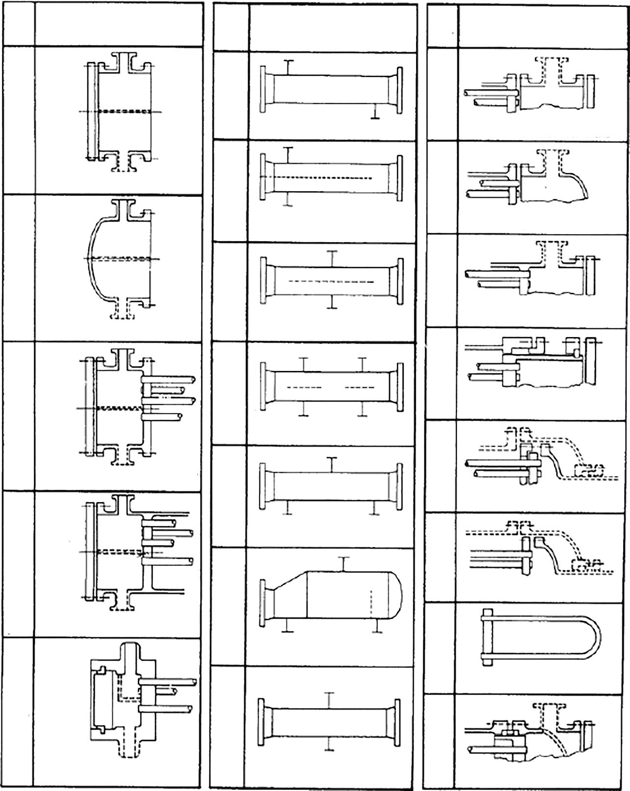
The chemical process industries (CPIs) require heat exchanger types to transfer heat from a hot stream to a cold stream. This heat transfer equipment must meet various codes/standards to deal with the thermal, mechanical, operational, installation and maintenance demands on the process. The optimal heat exchanger design should minimize operating costs and maximize product output. Shell and tube heat exchangers (Figures 21.1B–D) consist of a bundle of tube inside a cylindrical shell. One fluid (the tube side fluid) flows inside the tubes whilst the other fluid (the shell side fluid) flows through the shell and around the tubes. Heat is transferred across the tube wall separating the hot and cold streams. The shell type has a significant effect on the flow configuration and thermal performance of the heat exchangers. Shell and tube heat exchangers use baffles to transport heat to or from tube side process fluids by directing the shell side fluid flow. The increased structural support that baffles provide is essential to the tube stability, as they prevent the tube from sagging due to structural weight and also minimize vibration due to cyclic flow forces. Baffles improve heat transfer at the expense of increased pressure drop. Tubesheets seal the ends of the tubes, ensuring separation between the two streams.
The process engineer needs to understand the terminology of the heat-transfer equipment manufacturers in order to properly design, specify, evaluate bids, and check drawings for this equipment.
FRONT END STATIONARY HEAD TYPES
CHANNEL AND REMOVABLE COVER
BONNET (INTEGRAL COVER)
CHANNEL INTEGRAL WITH TUBESHEET AND REMOVABLE COVER
PASS SHELL WITH
RAFFLE
REAR END HEAD TYPES
CHANNEL INTEGRAL WITH TUBESHEET AND REMOVABLE COVER
FLOW
PASS SHELL FIXED TUBESHEET LIKE “A” STATIONARY HEAD FIXED TUBESHEET LIKE “B” STATIONARY HEAD FIXED TUBESHEET LIKE “N” STATIONARY HEAD OUTSIDE PACKED FLOATING HEAD FLOATING HEAD WITH BACKING DEVICE PULL THROUGH FLOATING HEAD U-TUBE BUNDLE EXTERNALLY SEALED FLOATING TUBESHEET
Figure 21.1A Nomenclature for Heat Exchanger Components. Figures 21.1A–G used by permission: Standards of Tubular Exchanger Manufacturers Association, 7th Ed., © 1988. Tubular Exchanger Manufacturers Association, Inc.
The shell and tube exchanger consists of four major parts:
• Front header—this is where the fluid enters the tube-side of the exchanger. It is sometimes referred to as the stationary header.
• Rear header—this is where the tube-side fluid leaves the exchanger or where it is returned to the front header in exchangers with multiple tube-side passes.
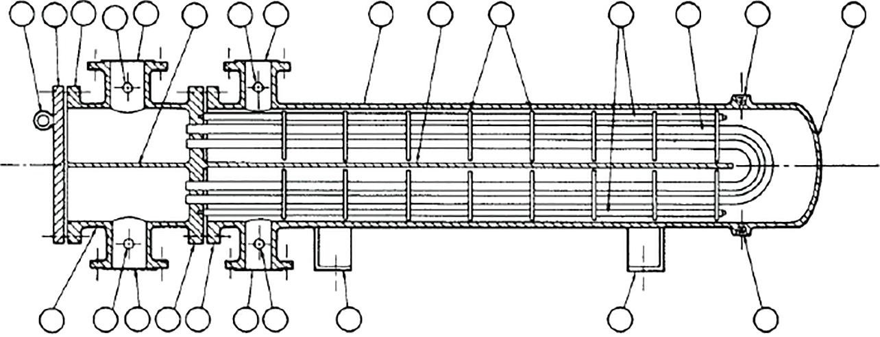
Figure 21.1E Removable U-bundle (© 1988 by Tubular Exchanger Manufacturers Association, Inc.).
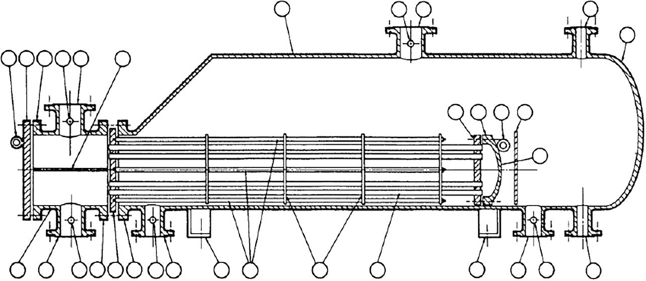
Figure 21.1F Kettle reboiler (© 1988 by Tubular Exchanger Manufacturers Association, Inc.).
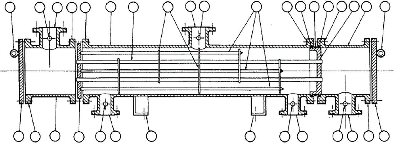
Figure 21.1G Divided flow-packed tubesheet (© 1988 by Tubular Exchanger Manufacturers Association, Inc.).