IntroductiontoHolographic
PIERRE-ALEXANDREBLANCHE,PHD
ASHORTHISTORY
Welcometothebeautifulworldofholography.With theirshimmeringcolorandghostlikeappearance,hologramshavetakenaholdinthepopularimagination, andbuzzmarketingalike.Thisisarareaccomplishment forascientifictechnique,thatworthtobenoted. Togetherwiththisgeneralappreciation,comesthe misinterpretation.Theword “hologram” issometimes associatedtothephenomenathathavenothingtodo withthescientificusageoftheterm.Itisnotproblematicineverydaylife,butitcanbecomeconflicting whenthetechnologypenetratesthemarket.Wehave allheardaboutholographicglass,holographichow fromdeceasedartists,holographictelevision,princess Leiahologram,etc.Somearehologramsindeed,some arenot.Thisbookwillhelpdemystifyholography, andIhopeitwillhelpyougainanewappreciation forthetechniquethatcanbeappliedinalotofdifferent circumstances.
Thereexistthreepossiblewaystoalterorchangethe trajectoryoflight:reflection,refraction,anddiffraction. Inoureverydayexperiences,wemostlyencounterreflectionsfrommirrorsand flatsurfaces,andrefractionwhen welookthroughwater,orwearprescriptionglasses.Scientistshaveusedreflectionandrefractionforover 400yearstoengineerpowerfulinstrumentssuchastelescopesandmicroscopes.IsaacNewton [1] championed theclassicaltheoryoflightpropagationasparticles, whichaccuratelydescribedreflectionandrefraction. Diffraction,ontheotherhand,couldnotbeexplained bythiscorpusculartheory,andwasonlyunderstood muchlaterwiththeconceptofwavepropagationof light, firstdescribedbyHuygens [2],andextensively developedlaterbyYoung [3] andFresnel [4]
Wavepropagationtheorypredictsthatwhenthe lightencountersanobstaclesuchasaslit,theedges donot“cut” asharpborderintothelightbeam,asthe particletheorypredicted,butratherthereisformation ofwaveletsthatpropagateonthesideinnewdirections.
Thisisthediffractionphenomenon.Eventually,theparticleandwavepointsofviewwillbereconciledbythe quantumtheory,andthedualityofwaveparticlewas developedbySchrödinger [5] anddeBroglie. [6,7]
Whilethelightpropagationfrommirrorsandlenses canbeexplainedwiththethoroughunderstandingof reflectionandrefraction,holographycanonlybe explainedbyrecognizingdiffraction.Ahologramis nothingbutacollectionofpreciselypositionedaperturesthatdiffractsthelightandformsacomplexwave frontsuchasathree-dimensional(3D)image.Inadditionbecausethelightisconsideredasawaveinthese circumstances,boththeamplitudeandthephasecan bemodulatedtoformthehologram.Amplitudemodulationmeanslocalvariationofabsorption,andphase modulationmeansachangeintheindexofrefraction orthicknessofthematerial.Inthelattercaseofphase modulation,theholographicmediacanbetotally transparent,whichaccountforapotentiallymuchefficientdiffractionoftheincidentlight.Wewilldescribe thedifferentpropertiesofhologramsin Section2
Hologramsareverywellknownfortheaweinspiring3Dimagestheycanrecreate.Buttheycan alsobeusedtogeneratearbitrarywavefronts.Examples ofsuchwavefrontsarefocalizationexactlylikealens,or reflectionexactlylikeamirror.Thedifferenceofthehologramfromtheoriginalelement(lensormirror)is that,inbothcases,diffractionisinvolved,notreflection orrefraction.Thattypeofhologram,calledholographic opticalelement,isfoundinopticalsetupswherefor reasonofspace,weight,size,complexity,orwhenitis notpossibletouseclassicalopticalelements.Someexamplesincludecombinerinhead-updisplay,dispersiongratinginspectrometers,orspotarraygenerators forcamerasandlaserpointers.
Therearetwoverydifferenttechniquesfor manufacturingholograms.Onecaneithercomputeit orrecorditoptically.Computingaholograminvolves thecalculationofthepositionoftheaperturesand/or
phaseshifters,accordingtothelawsoflightpropagation derivedbyMaxwell [8].Thiscalculationcanbefairlyeasy forsimplewavefrontssuchasalens,forextremely complicatedforhigh-resolution3Dimages.Ontheother hand,opticallyrecordingahologramimpliestheregistrationofboththeamplitudeandthephaseofthewavefront.Capturingthelightintensitywas firstachieved withtheinventionofphotographybyNiépcein1822. Butrecordingthephaseeludedscientistsuntil1948. Althoughtheconceptofopticalinterferencewasknown forages,itisonlywhenDennisGaborintroducedthe conceptofmakinganobjectbeaminterferewithareferencebeamthatrecordingthephasebecamepossible [9,10].Indeed,whentwocoherentbeamsintersect, constructiveanddestructiveinterferencesoccursaccordingtothephasedifference,thistransformsthephaseinformationintointensityinformationthatcanbe recordedthesamewayphotographsaretaken.Insome sense,thereferencebeamisusedtogenerateawavecarrierthatismodulatedbytheinformationprovidedby theobjectwave(similarlytoAMradio).
GaborcoinedthetermholographicfromtheGreek words holos: “whole” and graphe: “drawing” because thetechniquerecordedforthe firsttimetheentirelight fieldinformation:amplitudeandphase.Gaborusedthe techniquetoincreasetheresolutioninelectronmicroscopyandreceivedtheNobelPrizeinPhysicsin1971 forthisdiscovery.
Owingtotheveryshortcoherencelengthofthelight sourcesavailabletoGaboratthetime,theobjectand referencebeamsrequiredtobecolinear.Unfortunately, thisconfigurationyieldtoverypoorimagingquality becausethetransmittedbeamand 1diffractedorders weresuperimposed,leadingtohighnoiseanda “twinimage” problem.
Holographicimagingwillhavetowaitfortheinventionofthevisiblelightlaserin1960byMaiman [11], andforLeithandUpatniekstoresolvethetwin-image problem [12,13].Usingalongcoherencelengthlaser source,onemaydivideabeamintotwoparts oneto illuminatetheobject(theobjectbeam)andtheother (thereferencebeam)iscollimatedandincidentatan angletothehologramrecordingmaterial.Asaresultof thehighdegreeofcoherence,theobjectandreference beamswillstillinterferetoformthecomplexinterference patternthatwecallthehologram.Onreconstruction,a monochromaticbeamisincidenttotherecordedhologramandthedifferentdiffractedwavesareangularly separated.Thisway,the0, þ1,and 1orderscanbe observedindependently,solvingtheproblemofboth noiseandtwinimagesobservedinin-lineholograms. Section6 willdescribethedifferentconfigurationtorecordholograms.
Inparallel,andindependentlytoLeithandUpatnieks,Denisyukworkedonhologramswheretheobject andreferencebeamsareincidentthehologramplane fromoppositedirections [14 16].Suchholograms areformedbyplacingthephotosensitivemediumbetweenthelightsourceandadiffuselyreflectingobject. Inadditionofbeingmuchsimplerandmorestableto record,thesereflectionhologramscanbeviewedbya whitelightsourcebecauseonlyanarrowwavelengthregionisreflectedbackinthereconstructionprocess.We willseethefundamentalreasonforthisselectivityin Section2.3 aboutthecharacteristicsofthickholograms.
Oncehigh-qualityimagingandcomputer-generated holograms(CGHs)weredemonstrated [17,18],the researchonholographyexperiencedaphenomenal growth,expandingtoencompassalargevarietyofapplicationssuchasdatastorage [19],informationprocessing [20],interferometry [21],anddynamicholography [22] tociteonlyafew.Today,withthewidespreadaccessto activeLCoSandMEMSdevices,thereisarejuvenation oftheholographic fieldwhereanewgenerationofresearchersisapplyingthediscoveriesofthepastdecades toelectronic-controlledspatiallightmodulators.New applicationsareonlylimitedbytheimaginationofscientistsandengineers,anddevelopmentsarecontinuously beingreportedinthescientificliterature.
Thischapterwillcontinuebydevelopingthetheory ofthickandthindiffractiongratings.Oncethesebases havebeenestablished,wewillmovetothescalartheory ofdiffractionthatshowshowtocalculatethelight field fromadiffractiveelement,andviceversa.Wewill finish bydescribingseveralimportantexperimentalsetup usedtorecordholograms.
DIFFRACTIONGRATINGS
WavesandInterference
Agreatdealcanbeunderstoodaboutholography withoutthecomplicationofimaging,andbysimply lookingatthepropertiesofdiffractiongratings.Diffractiongratingsareparticularhologramswheretheinterferencesfringes,orBragg’splanes,areparallel.As such,theytransformoneplanewaveintoanotherplane wavewithadifferentdirection.Thissimpleactionon thelightbeammakesthemathematicalformalism mucheasiertounderstand.
Aftertheanalysisofsimplegratings,holographicimagescansimplybeviewedasthesuperpositionof severalplanarwavefronts,andthehologramitselfcan beviewedasthesuperpositionofseveralgratings, muchlikeFresnelandFourierdecompositions.
Maxwell’sequationdefinesthepropertiesoftheelectromagnetic field.Inaddition,formostholographic
applications,themagnetic fieldcanbeneglected withoutlossofgenerality.Inthatcase,onlytheHelmholtzequationremainstodefinetheelectric field E: 1 c2 v2 E vt 2 V2 E ¼ 0 (1.1)
with c beingthespeedoflightandboldfacefontused torepresentvectors.
Asolutionofthisdifferentialequationhastheform ofaplanewave:
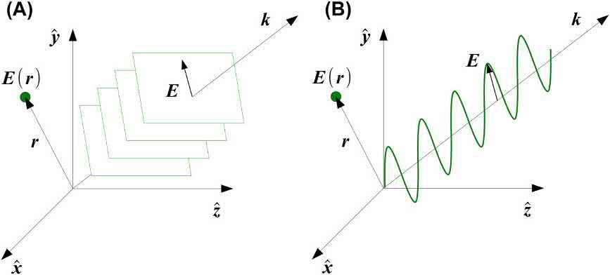
where A isanimaginaryvectordescribingthedirection oftheelectric fieldoscillation,andcontainthepolarizationinformation, k isthewavevectorpointinginthedirectionoflightpropagationwhichmagnitudeisrelated tothewavelength jkj¼ 2p/l r isthepositionvector definingthepositionatwhichthe fieldiscalculated, u isthefrequency,and f thephaseofthewave.Two equivalentrepresentationofaplanewaveareillustrated in Fig.1.1.Ithastobenotedthatasphericalwavefront isalsosolutionoftheHelmholtzequation.
UsingEuler’sformulaexp(ix) ¼ cosx þ isinx,the planewavesolutioncanberewrittenas:
Uðr ; t Þ¼ A exp½iðk $ r ut þ f b a(1.3)
wherethepolarizationvector b a hasbeenextractedfrom theamplitudevector A whichisnowthescalar A
Oneneedtokeepinmindthattheactualelectric field E istherealpartofthecomplexnotation U in Eq.(1.3):
Whentwoplanewavesoftheformof Eq.(1.3) cross eachother,interferenceoccurs.Thetotal fieldcanbe describedas:
wherethesubscriptsnumber1and2describingthetwo waves.
Inthisformulation,wecanseethatthepatternisnot necessarilystaticbutchangeasafunctionoftime.Itis onlyinthespecialcasewhere u1 ¼ u2 that Eq.(1.5) becomestimeinvariantandcanbeexpressedinasimpler form,wherethetotalintensityis
wherethe*denotesthecomplexconjugate.
Tomaximizethecontrastbetweendark(destructive interference)andbright(constructiveinterference)regionsoftheinterferencepattern,thepolarizationof thewaveshouldbeidentical b a 1 ¼ b a 2 ,andtheequation reducestothefamiliarform:
Thisintensitymodulationcanberecordedinsidea materialasanindexmodulationorabsorptionmodulationpatterntoformadiffractiongrating.
Eq.(1.7) describingtheintensitymodulationin space,canberecastasastaticplanewavewithawave vectordefinedas:
FIG.1.1 Planewaverepresentationas (A):planeofequal fieldintensityor (B):oscillationoftheamplitudeof the fieldalongthewavevector k
E
Similartothedefinitionof k1 and k2 thatarethe wavevectorsofthelightbeams, K isthegratingvector oftheinterferencepattern.Themagnitudeofthegrating vector k2 isrelatedtothespacing L betweentwoplanes ofequalmagnitude,alsocalledtheBragg’splanes:
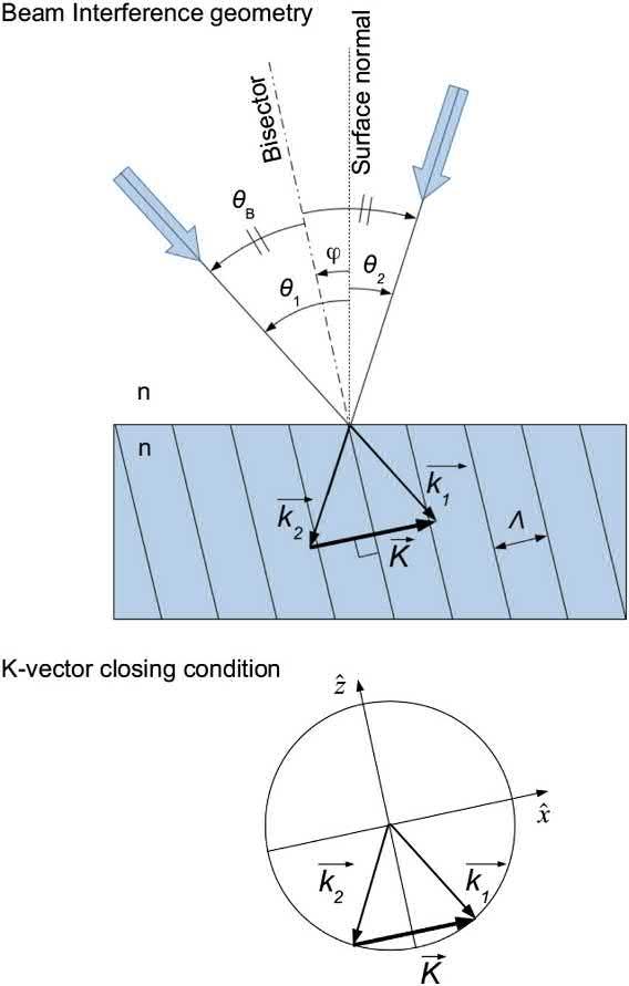
Duringthereadingofadiffractiongrating,anincidentplanewavedefinedbythewavevector ki encounterstherecordedgrating K andisdiffractedinthe direction kd accordingtotheK-vectorclosingcondition: jKj¼ kd ki (1.10) TheK-vectorclosingconditionisidenticaltothegrating equationdevisedfromcrystallographicmeasurements wherethemodulationplaneswereactuallyrowsof atoms:
where qd istheangleofdiffraction, qi istheangleofincidence,and m isanintegernumberthatde finesthe diffractionorder.
Bothgeometriesareshownin Fig.1.2 withthedefinitionoftheangles.
Theangulardispersionasafunctionofthefrequency canbedirectlyderivedfromthegrating Eq.(1.11)
From Eq.(1.12),itcanbeseenthatthelowerfrequencies(red)arediffractedatalargeranglethanthe higherfrequencies(blue).Thisisthereversefrom whatisobservedwitharefractiveprism(withnormal indexdispersion),wherehigherfrequenciesexitata largerangle.Thisoppositioncanbeusedtomakean opticalsystemachromatic,withthediffractiveelement compensatingthedispersionoftherefractivelens.
Thedirectionofthediffractionmaximumsaregiven bytheBragg’slawthatcanbeunderstoodastheconditionforconstructiveinterferenceforthelightinteracting withtwosuccessivediffractionplanes:
FIG.1.2 Definitionoftheanglesandvectorsforthebeam interferencegeometry,andK-vectorclosingconditionfor thesamegeometry.
indicationontheintensityofthewavebeingdiffracted, onlythe directionandfrequency.Thecalculationofthe waveintensity,ordiffractionefficiency,accordingto thegratingparameterswillbederivedin Section2.3 forthickvolumegrating,andin Section2.4 forthinor surfacereliefgratingwithdifferentformatmodulation.
PointSourceInterference
Armedwiththegeneralequationfortheinterferencebetweentwowaves(Eq.1.7),letusderivesomespecific casesandobservethepatternformedbythefringes.
where qB istheangleofincidenceforwhichthereisa maximumofdiffractedintensity,alsocalledBragg’ s angle, 4 istheslantangleofthegrating,thatis,theangle betweenthegratingvectorandthenormaltothegrating surface(see Fig.1.2).
Itshouldbenotedthatthegratingequations expressedin Eqs.(1.10) (1.13)donotgiveany
Two-planewaves
Inthecaseoftwo-planewavethathavedifferentincidenceangles,thephaseandintensityarerespectively givenby:
fi ¼ 2p l x sin qi Ii ¼ 1 (1.14)
Insertedinto Eq.(1.7),wefoundfortheinterference pattern:
whichisidenticaltothegrating Eq.(1.11) witha patternfrequencyof:
Thisexpressiononlybecameinterestingbylooking atparticularcasessuchasthetwothatfollow.
Side-by-sidepointsources
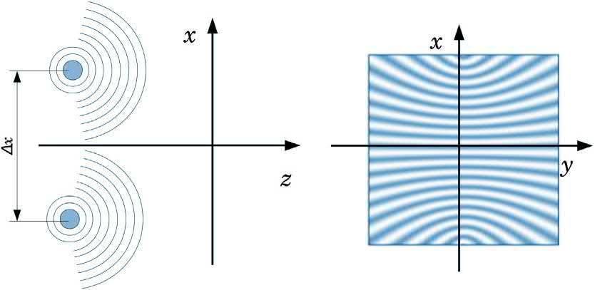
Forpointsourcesthatarelocatedsidebysidealongthe x axis,withaseparationdistanceof Dx,andifwe consideraconstantintensity,wecandescribethephase andintensityas:
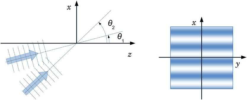
Thegeometryofthisconfigurationalongwiththe interferencepatternformedisshownin Fig.1.3. Wecanseethattheinterferencepatternonlyvaries alongonedimension(x).Therecordingofthispattern insideamaterialformsadiffractiongrating.
Arbitrarypointsources
Insteadofusingplanewaves,wecanusespherical waveswitharbitraryorigins(xi, yi, zi).Theirphaseand intensityisnowdescribedby:
Inallgeneralities,theinterferencepatternis
Sotheinterferencepatternbecomesarelativelysimpleexpression:
Thegeometryofthisconfigurationalongwiththe interferencepatternformedisshownin Fig.1.4.
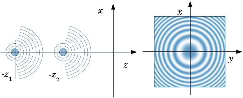
Collinearpointsources
Forpointsourcesthatarelocatedonthe z axisbutat differentdistances,andconsideringaconstantintensity, thephaseandintensityaregivenby:
i ðx; y Þ¼ 2p l zi þ p lzi x2 þ y 2 Ii ¼ 1 (1.21)
FIG.1.3 Geometryandinterferencepatternproducedbytwo-planewavesincidentatdifferentangles.
Theinterferencepatternis
Thegeometryofthisconfigurationalongwiththe interferencepatternformedisshownin Fig.1.5.We willseeanidenticalpatternwhenwewillstudythe Gaborzoneplatein Section3.4.4.
Ithastobenotedthatfromtheperspectiveofthe pointsources,thetwocaseswejustdevelopedareidentical.Thetwointerferencepatternsareformedeitheron theside,oralongtheaxisofseparationofthetwosources.
ThickGrating’sCharacteristics
Theinterferencepatternformedbytwo-planewaves wasintroducedin Fig.1.3 .Oncethispatternis recordedinsideamaterial,itformsadiffraction grating.Thedirectionofthediffractedwavecanbe determinedusingthegrating Eq.(1.11) .Nowweare
goingtostudythedistributionofenergyaroundthe Bragg’sangleandtheBragg’ swavelengthforthick diffractiongratings.
Thesedistributionshave firstbeenderivedbyKogelnikinhiscoupledwavetheory [23].Anotherderivation thatalsogiveverygoodresultsiscalledtheparallel stackedmirrormodelandhasbeenintroducedby Brotherton-Ratcliffe [24,25].Thesetwomodelsgive analyticalsolutionsinthecasewhenthegratingsatisfies theBragg’sconditionfor “thick” gratings.
Thickgratingcriteria
Thisthickgratingconditionissomewhatmisnamed becauseitisnotbasedonthephysicalthicknessof thematerial,butonthepremisethatmostoftheenergy isconcentratedinthe firstdiffractionorder.ThisconditionofoperationisalsocalledtheBraggregimeandis indeedobservedingratingsandhologramsforwhich therecodingmediaareratherthick.Thisisbecause,in thiscondition,theincidentbeaminteractsseveraltimes
I
FIG.1.4 Geometryandinterferencepatternformedbytwopointsourceslocatedsidebyside.
FIG.1.5 Geometryandinterferencepatternformedbytwopointsourceslocatedalongtheaxisoflightpropagation.
withthegratingstructure,andthereisaprogressive transferofenergyintothediffractedbeam.
Bycontrast, “thin” gratingsoperatedintheRamanNathregimeofdiffractionwhereanappreciable amountofenergycanbefoundinhigherordersof diffraction.Owingtotheirsmallerthickness,thetransferofenergyisnotrestrictedtothe firstorders.Theenergydistributiondiffractedbythingratingcannotbe calculatedusingtheKogelniktheoryortheparallel stackedmirrormodelandrequiresthemoreextensive andlaboriousrigorouscoupledwaveanalysisdevelopedbyMoharamandGaylord [26]
Thereisnotacleardividingboundarybetweenthin andthickgratings.Instead,severalcriteriahavebeen devisedaccordingtotheapproximationsusedinsolvingthecoupledwaveequation,andaccordingtotheresultsobservedexperimentally.
Twoofthemostusedcriteriatodistinguishbetween thickandthingratingsaretheKleinandCookcriteria [27],andtheMoharamandYoungcriteria [28].
KleinandCookcriteria:
with Q0 < 1forthingratings,and Q0 > 10forthick gratings.
TheMoharamandYoungcriteria:
where Dn isthematerialindexmodulation,and r < 1 definesthingratings,when r 1definesthickgratings. Wecanseethatthiscriteriondoesnoteventakethe physicalthickness(d)ofthegratingintoaccount.
Tosatisfythethickgratingcriterion,theBragg’ s planesneedtoextendtoacertainvolumeinsidethe material(thusthename).Suchadiffractionstructure cannotbejustoverlaidonthesurface.Theadvantage ofthickgratingisthatmostofthediffractedenergyis foundinthe firstorder.Forthatreason,thickgrating areofparticularinterestinholographicimagingandengineeringbecauseonedoesnothavetodealwithlight presentinhigherdiffractionorders,whichinducenoise andreduceefficiencyinthedesired first-orderimage.
Efficiencyofthickgratings
Therigorousderivationofthickgratingdiffraction efficiency,expressedastheratiobetweenthewaveintensityinthe firstorderandtheincidentintensity,can befoundintheoriginalpublications [23,24].Here, wewillsummarizetheprincipalresultsinthespecial casesofunslanted(4 ¼ 0or p/2),phase(Dn),and amplitude(Da)sinusoidalmodulation.Forthesespecificconditions,themathematicalexpressionssimplify dramatically,anditishelpfultokeepinmindthegeneraltrendastheygiveagoodintuitionforothercases.
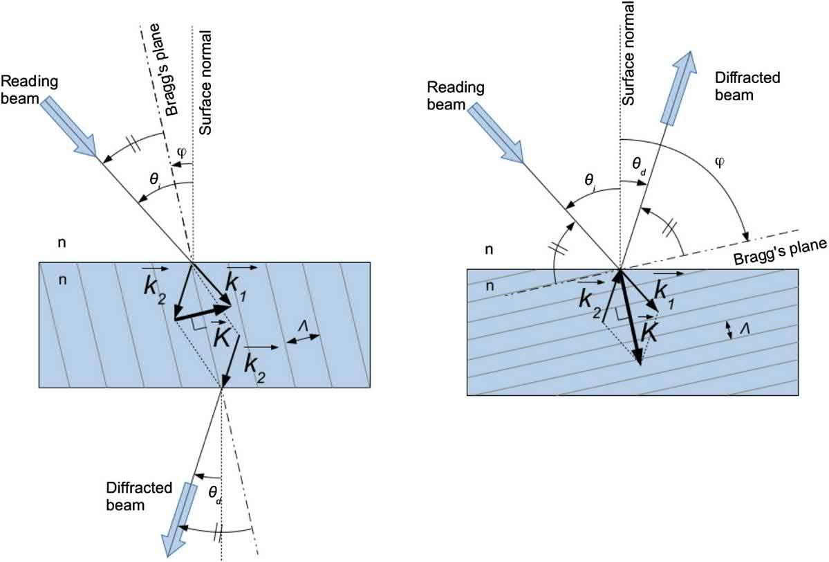
Inadditiontothemodulationformat(phaseand amplitude),twodifferentconfigurationsofthegrating willbediscussed:transmissionandreflection.Illustrationofthesetwogeometriesareshownin Fig.1.6, whereaslantangle 4 hasbeenintroducedforthesake ofgenerality.
Intransmissiongeometry,thediffractedlightexits thegratingbytheoppositesideoftheincidentlight: thelightgoesthroughthegrating.Todoso,theBragg’ s planesareorientedmoreorlessorthogonaltothe gratingsurface.Thegratingfrequencyintransmission geometryrangefrom300to3000linepairspermm (lp/mm)forvisiblelight.
Inthereflectiongeometry,thediffractedlightexitsthe gratingbythesamesideoftheincidentlight,thelightreflectedbackfromthegrating.Inthisgeometry,the Bragg’splanesareorientedmoreorlessparalleltothe surface,andthegratingfrequencyisover4000lp/mm.
Phasegratings,wheretheindexofrefractionis modulated,canreach100%efficiencyeitherintransmissionorinreflection.TheexpressionforTE(transverseelectrical)modeisrespectivelygivenby:
Fortransmissionconfigurationand:
Forreflectionconfiguration.
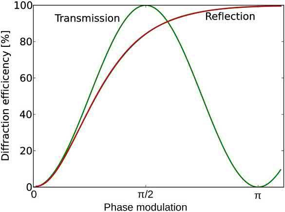
Plotsofthesefunctionsaccordingtotheindexmodulationamplitude(Dn)areshownin Fig.1.7.
Itshouldbeobservedthatinthecaseofatransmissiongrating,theefficiencyisaperiodicfunction(sin) thatreachesitsmaximumwhenthephasemodulation equal mp/2(m beinganinteger).Whenthephasemodulationextendspastthe firstmaximum,thegratingis saidtobeovermodulated,andthelightstartstobe
Themanufacturingofthickgratinggenerallyinvolves therecordingofaninterferencepatternusinganoptical setup,techniquesthatwillbedetailedin Section6.The reasonforopticalrecordingisthatthediffractivestructuresneedtobeembeddedinsidethevolumeofthe material,whichisdif ficulttoaccessotherwise.Itis alsopossibletoproducediffractivestructuresthat satisfythethickgratingconditionsusingmultilayer coatingofdielectriclayers.Suchstructuresarebetter knownasdichroicmirrorsorinterference filters.
FIG.1.6 Definitionoftheanglesandvectorsfortransmission(left)andreflection(right)gratings.TheK-vector closureconditionisalsodrawnforeachgeometry.
FIG.1.7 DiffractionefficiencyofaphaseBragg’sgratingin transmissionorreflectionaccordingtotheindexmodulation amplitude Dn
coupledbacktothezeroorder,reducingtheefficiency. Theminimumisreachedwhen Dn ¼ mp. Inthereflectionconfiguration,thediffractionefficiencymonotonicallyincreases,andthereisno
overmodulationpossible.Thereasonisthatthelight transferredintothe firstorderexitsthemediaand doesnotpropagatefurtherintothevolumewhereit wouldhavehadachancetobecoupledbackintothe zeroorder.
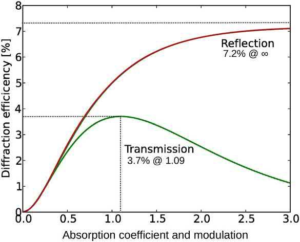
Amplitudegratings arelessefficientthanphasegratingsbecausethemodulationisbasedontheabsorption ofaportionoftheincidentlight.Volumeamplitude gratingsdoexceed7.2%efficiency.Theexpressionfor TEforatransmissiongratingis
where a istheabsorptioncoefficientandcanreach valueshigherthan1, Da isthemodulationofthat coefficient.
Eq.(1.27) exhibitsamaximumefficiencyof3.7% when a ¼ Da ¼ ln3.
Foranyvalueoftheabsorption a,themaximumefficiencyisachievedwhenthemodulationismaximum: Da ¼ a.
Forthereflectioncase,theTEefficiencyisgivenby:
wheretheparameter A denotestheabsorptionterm:
A ¼ ad/cos qi
Theefficiencyforthereflectionamplitudegrating monotonouslyincreaseswiththemodulation,asymptoticallyapproachingamaximumof7.2%.
Plotsofthediffractionefficiencyaccordingtothe modulationwhen a ¼ Da fortransmission(Eq.1.27) andreflection(Eq.1.28)Bragg’sgratingsareshownin Fig.1.8.
ThesolutionsfortheTM(transversemagnetic) modeshouldbeadjustedfromtheTEsolutionswith thecouplingfactor kk addedtothemodulationfactor, either Dn or Da:
ThisisduetotheverydifferentBragg’splanefrequencies(L)observedforthesegeometries.Inthe transmissiongeometry,thegratingfrequencyranges from300to3000lp/mm,whereasinthereflectiongeometrythegratingfrequencyismorethan4000lp/mm. TheexpressionsforphasegratingsinTEmodefor thedifferentcasesarethefollowing:
TRANSMISSIONCONFIGURATION
AngularDispersion
Dispersionofthickgratings
Thecoupledwavetheoryalsoallowsthederivationof dispersionforeachconfigurationaccordingtowavelengthandtheangularincidence [23].Moreimportantly,oneneedstorecognizethatevenwiththesame characteristicsofthicknessandmodulationamplitude, transmissionandreflectiongratingshaveverydifferent behaviorswhenitcomestodispersionandselectivity.
FIG.1.8 DiffractionefficiencyofanamplitudeBragg’s gratingintransmissionorreflectionaccordingtothe absorptioncoefficient,andassumingmaximummodulation amplitude. a ¼ Da
withthedetuningparameter Dli givenby:
REFLECTIONCONFIGURATION
AngularDispersion
Withtheparameter Ai givenby:
Andthedetuningparameter Dqi isgivenby:
Withtheparameter Bi givenby:
Andthedetuningparameter Dli givenby:
Notethatthesedispersion Eqs.(1.30 1.34),(1.37) canbefurtherapproximatedbysinc2 functionswiththe appropriatedetuningcoefficients.
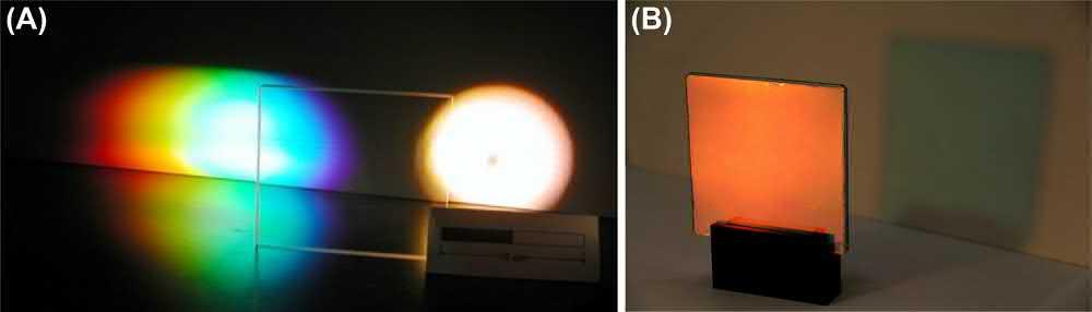
TypicalangularandspectraldispersioncharacteristicsofreflectionBragg’sgratingsareillustratedin Figs.1.9and1.10.Generallyspeaking,transmission gratingarediffractingalargebandwidthofwavelengths eachataveryspecificangles,theyproducearainbow. Theyarewavelengthtolerantandangularlyselective. Ontheotherhand,reflectiongratingsdiffractavery
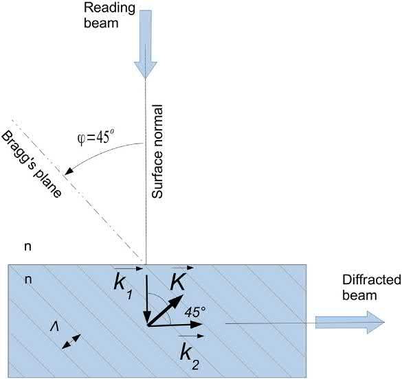
narrowbandwidthatanyangle,theyactasanotch filter,reflectingonesinglecolor.ReflectionBragg’sgratingsarewavelengthselectiveandangularlytolerant. Althoughtheserulesofthumbbehaviorforthe differenttypeofgratingsareveryusefultokeepin mind,theycanbeprovedwrongforparticularcases suchasedge-litgratings(4 ¼ p/4)thatfallinbetween thetwocategories,orforverythickgratings (d > 100 mm)thatareextremelyselectiveinbothangle andwavelengthindependentlyoftheirconfiguration. Edge-litgratingshaveaslantanglecloseto45 (Fig. 1.11).Theirnamecomesfromthefactthattoachieve thisangle,oneofthebeamsneedstobeincident fromtheside(edge)ofthematerial.Thistypeofgrating isusefulforinjectingorextractingthelighttoandfrom awaveguide.Thistypeofconfiguration,usinga waveguide,hasrecentlygainedpopularityforsolar concentrationapplication [29],augmentedrealityseethroughdisplays [30,31],andhead-updisplay [32]
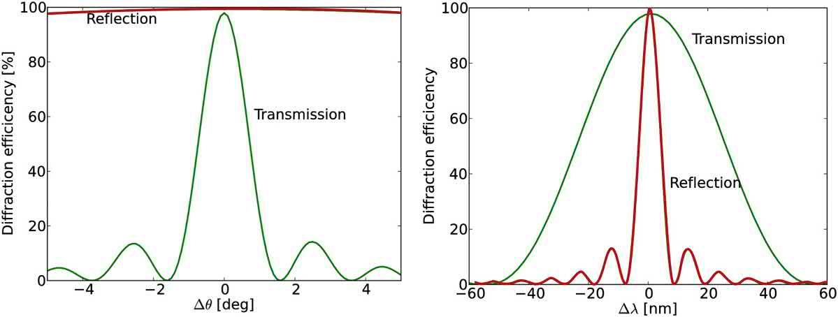
FIG.1.9 Typicalangular(left)andspectral(right)dispersionofatransmissionorreflectionBragg’sgratings. Generallyspeaking,transmissiongratingsareangularlyselective,whenreflectiongratingsarewavelength selective.
FIG.1.10 Pictureofvolumephaseholographicgratings. (A) Transmissiongratingthatdispersestheincident lightintoarainbow. (B) Reflectiongratingthatselectivelydiffractstheredportionofthespectrum.Both hologramsaremadefromthesamematerial(dichromatedgelatin)andareilluminatedbyahalogenwhitelight.
FIG.1.11 Geometryofanedge-lithologram.Thediffracted beamisevanescent,thatis,directedparalleltothesurfaceof thematerial.
Theangleandfrequencyselectivitypropertiesofedge-lit hologramsareinbetweenthoseobservedfortransmissionandreflectiongratings(Fig.1.9).Theseproperties areidenticaleitheriftheedge-lithologramisusedin reflection(hologramplacedatthebottomofthewaveguide),ortransmission(hologramplacedatthetopof thewaveguide).Thisisbecausethehologramparameters,angleandfrequency,changeonlyveryslightlybetweenthetwoorientations.
Multiplexing
Becausethickgratingscanbemadehighlyselectiveaccordingtothereadingangleorwavelength,itispossible torecordmultiplehologramsatthesamelocation,and inthesamematerial,whichdonotinterferewitheach other.Thismeansthatonehologramcanberead withouthavinganylightdiffractedbytheothersholograms.Thistechnique,knownasmultiplexing,isparticularlyusefulfordatastoragewherethememorycapacity canbeincreasedthousandsoftimes [33].Itisalsoused forcreatingcolorhologramsfromthreehologramsdiffractingindividuallythered,green,andbluecolors [34].Aparticularcaseofwavelength-multiplexedhologramistheLippmannphotographythatwillbeintroducedin Section6.10.1[35]
Thegratingvector K canbemodi fiedintwoaspects: magnitudeanddirection.So,twotypesofmultiplexing arepossible:angularandwavelength.Inangularmultiplexing,thedirectionofthegratingvectorischangedby
usingdifferentincidenceanglesforeachhologram.In wavelengthmultiplexing,themagnitudeofthegrating vectorischangedforeachhologrambyusingdifferent wavelengthstorecordthem.
Asageneralrule,theef fi ciencyofeachhologram duringmultiplexingfollowsa 1 N 2 H lawwhere NH is thenumberofholograms.Indeed,ifthemaximumdynamicrange(amplitudeorphase)ofthematerialis DM eachmultiplexedhologramisusingaportion ofthisrange,sothemodulationperhologramis DM /N H.Astheef fi ciencyisproportionaltothesquare ofthemodulation( Eqs.1.25and1.26 ),weobtainthat hf1 N 2 H
Thisrelationshipisonlyvalidforthecaseswherethe hologramcannotbeovermodulated.Overmodulation meansthattheopticalpathdifference(Dn d)thatcan beachievedinthematerialislargerthanthe p/2necessarytoobtainmaximumefficiency: h ¼ 100%.When thematerialisextremelythick,orwhenthemodulation canbemadeextremelylarge,itispossibletorecord severalmultiplexedhologramswitheachonehaving 100%efficiencyfordifferentincidentanglesorwavelengths,ofcourse.
Animportantmetricinmultiplexedhologramsisthe crosstalk.Thisistheratiobetweenthesumoftheenergiesdiffractedbythehologramthatarenotinterrogated,andtheenergydiffractedbythehologramsthat isbeingread.Thecrosstalkisparttoofsignal-to-noise ratio(SNR)forthesystem.Assuch,itisoftenexpressed indecibel(dB).
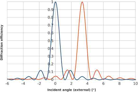
Fig.1.12 showstheangularselectivityoftwohologramswiththesameparameters,butwithdifferentslant anglestoshiftthediffractionpeaksby3.5+.Althoughthe angularseparationofthemainlobeislargerthantheir full-widthhalfmax(1+),thecrosstalkisincreaseddue tothepresenceofsecondarylobesinthediffractionprofile.Atzerodegree,thecrosstalkis4.2%or 27.5dB.A lowercrosstalkcouldbeachievedbyusingashiftof either2.5+ or4+,wherethemainlobeswouldbealigned withaminimumfromtheotherhologram.
ThinGrating’sCharacteristics
ThingratingsoperateintheRaman-Nathregimewhere theincidentwaveinteractsonlyafewtimeswiththe modulation.Thiscanbeonlyonesingletimeasfor thecaseofsurfacereliefgratings. Eqs.(1.23)and (1.24)mathematicallydescribetheconditionforthe thingratingregime.Inthismodeofoperation,asubstantialamountofenergycanbecoupledinhigher diffractionorders(m > 1).However,thisisnotalways thecaseandathinsurfacereliefgratingcanbemade highlyefficientaswewillseeinthissection.
FIG.1.12 Angularselectivityoftwotransmissionholograms with634lp/mm,in100 mmthickmaterial,andat800nm wavelength.Althoughtheangularseparationoftheholograms islargerthanthemainlobefull-widthhalfmaxof1+,thecross talkisincreasedduetothepresenceofsecondarylobesin thediffraction.
Thingratingsareextremelyimportantbecausethey caneasilybemanufacturedbyprintingastructureobtainedbycomputercalculation.Mostoftheholograms encounteredindailylifesuchassecuritytagonbanknotesandluxurygoodsfallinthatcategoryandare madebytheembossingtechnique(seeChapter2on holographicmaterials).Thingratingscanalsobe dynamicallydisplayedusingelectronicallycontrolled spatiallightmodulatorssuchasLCoS(liquidcrystal onsilicon)andDLP(digitallightprocessor).
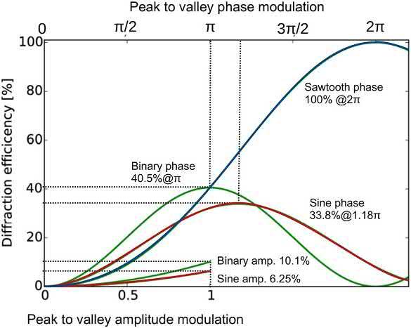
Theefficiencyofthingratingsdependsontheshape ofthemodulation [36].Asforthickgratings,onecan distinguishbetweenamplitudeorphasemodulation, butforthingratings,itisalsoimportanttorecognize thegeometricalformatoftheprofilesuchassquare,sinusoidal,orsawtoothpattern.
TherigorouscalculationoftheefficiencyandnumberofordersisbasedonFourierdecompositionof thecomplexamplitudeofthetransmittedwavefunction t(x)accordingtothegratingmodulation M(x).By findinganexpressionoftheform: t ðxÞ¼
Theportionoftheintensityinthe mth orderis hm ¼
A2 m ,andthedirectionofpropagationforthatorderis givenbythevector mK
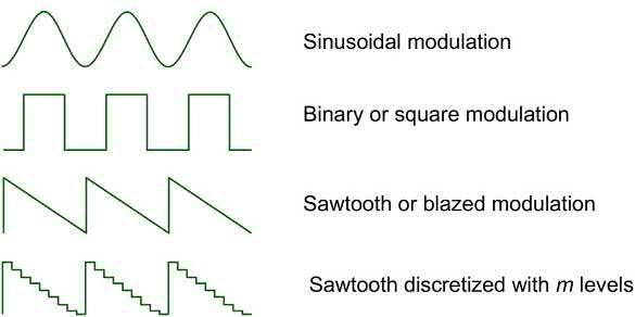
Wearegoingtoanalyzesixcasesthatarerelevantto today’sholographicmanufacturinganddisplays.These includethethreemodulationprofilesshownin Fig.1.13:sinusoidal,binary(orsquare),andsawtooth (orblazed).Foreachoftheseshapes,thetwopossible
FIG.1.13 Shapeofthemodulationformatforthingratings thataremathematicallyanalyzedinthetext.
modulationformatwillbeinvestigated:amplitude andphase.Wewillalsoconsiderwhathappenwhen thesawtoothprofileisdigitizedinto m discretelevels.
Sinusoidalamplitudemodulation
Forasinusoidalamplitudegrating,themodulation formatisgivenby:
t ðxÞj¼ MðxÞ¼ M0 þ DM 2 sinðKxÞ
M0 þ DM 4 expði K
where M0 ˛ [0,1]istheaveragetransmittance, DM ˛ [0,1]isthetransmittancepeaktovalleymodulation, and jKj¼ 2p/L isthewavevector.
Thethreedifferenttermsontherightsideof Eq. (1.41) areassociatedwiththeamplitudeofthedifferent diffractionorders:0, þ1, 1respectively.Thereareno higherordersforsuchgrating.Thediffractionefficiency (h ¼jt 1j2)foundinthe 1orderforthismodulation isgivenby:
whichismaximumwhen M0 ¼ DM/2 ¼ 1/2.
Thebehaviorofthediffractionefficiencyasafunctionoftheamplitudemodulation DM isplottedin Fig.1.14.
Sinusoidalamplitudegratingscanbefabricatedby recordinganinterferencepatternintothinlayerofsilver halideemulsionandthenchemicallyprocessedto revealthelatentimage.
Sinusoidalphasemodulation
Forasinusoidalphasegrating,thereisnoabsorption: t(x) ¼ 1,butthecomplexamplitudetransmittanceis givenby:
j
FIG.1.14 Diffractionefficiencyofthingratingsaccordingto themodulationshape(sine,square,sawtooth),format (amplitudeorphase),andmodulationamplitude DM
Sinusoidalphasegratingscanbefabricatedby recordinganinterferencepatternintoaverythinlayer ofphotopolymerordichromatedgelatinandprocessingtheemulsiontoboosttheindexmodulation.
Binaryamplitudemodulation
Forabinaryamplitudegrating,themodulationisa squarefunction,andtheFourierdecompositionis expressedas:
where M0 isaconstantphaseshift,and DM isthepeak tovalleyphasemodulation.
Ignoringtheconstantphaseshift,theright-handside of Eq.(1.43) canbeexpandedinaFourierseriesas:
Thetermsofthisdecompositionarealloddsdueto the2m 1expressionintheexponentialfunctions.In consequence,therearenoevendiffractionordersfor thistypeofmodulation.Thediffractionefficiencyfor the 1ordersisgivenby:
where Jm istheBesselfunctionofthe firstkindwiththe mth orderrepresentingtheamplitudeofthewaves, whentheexponentialtermsrepresentplanewavesdirection,thatis,thediffractedorders.
Fromthedecompositiongivenin Eq.(1.44),itcan beseenthatthereisaninfinitenumberofdiffractionorders(oneforeachtermofthesum).
Thediffractionefficiencyinthe firstordersisgiven by:
Maximumefficiencyisachievedwhen M0 ¼ DM/2 ¼ 1/2.
Thebehaviorofthediffractionefficiencyaccording tothepeaktovalleyamplitudemodulationisshown in Fig.1.14.
Binaryamplitudegratingshavebeenhistorically manufacturedbyusingofficeprintersontransparent films.Nowadays,thistypeofmodulationisfound whenaholographicpatternisdisplayedonaDLPlight modulator.TheDLPpixelsarecomposedofmirrorthat canbe flippedleftorright.Fortheincidentlightbeam, themirrorsactasnearlyperfectreflectororabsorber dependingofthedirectiontheyareoriented.
Binaryphasemodulation
Forabinaryphasegrating,thecomplexamplitude transmittanceisgivenbythefollowingexpression:
whichismaximumwhen dM ¼ 1.18.Noteherethat thisvalueof dM meansthatthepeaktovalleyphase modulationshouldbeslightlylargerthan p tomaximizetheefficiency.
Thebehaviorofthediffractionefficiencyaccording tothepeaktovalleyphasemodulationisshownin Fig.1.14
Thetermsofthedecompositionarealloddsdueto the2m 1expressionintheexponentialfunctions,so therearenoevendiffractionordersaswehaveseenin thecasefortheamplitudebinarygrating.However,
converselytotheamplitudecase,thephasemodulation termisnowcontainedintheexponentialandneedsto beexpandedto findthevalueoftheefficiency.Forthe m orders,theefficiencyis
withsinc(x) ¼ sin(px)/(px).
Forthe firstordersefficiency,wehave
whichismaximumfor DM ¼ 1,thatis,apeaktovalley phasemodulationof p/2.
Thebehaviorofthediffractionefficiencyaccording tothephasemodulationisshownin Fig.1.14
Binaryphasegratingcanbemanufacturedbyusing single-layerphotolithographicprocesswhereaphotoresinisselectivelyexposedandremoved.Thepatterncan beusedasit,inthiscase,thephasemodulationisgiven bythicknessoftheresinlayertimesitsindexmodulationminus1: DM ¼ d(n 1).Alternatively,theresin canbecoveredbyalayerofmetalthatmakethestructurereflective.Inthiscase,themodulationisgivenby twicethethicknessoftheresinlayerduetothedouble passofthelightinthegrooves: DM ¼ 2d
Acounter-intuitive,butnonethelessimportant, resultfromthisdecompositionexerciseisthatthe maximumdiffractionefficiencyinthe firstordersis largerforsquaregratings(40.5%forphase,10.1%for amplitude)thanforsinusoidalgratings(33.8%for phase,6.25%foramplitude).
Sawtoothphasemodulation
Forasawtoothphasegrating,whichisalsocalled blazedgrating,thecomplexamplitudetransmittanceis
pathlengthdifferenceistwiceaslargeduetothedouble passofthelight.
Discretizedsawtoothphasemodulation
Foradiscretizedsawtoothphasegrating,therampis composedof m levelsspacedapartatequalamplitude (see Fig.1.13).Thisconfigurationisimportanttoderive because,formanymanufacturingprocesses,itisnot possibletoreproduceaperfectlysmoothsawtoothprofile.Instead,theslopeiscomposedofmultiplediscrete steps.Forexample,itispossibletoexposeandetch photo-resinseveraltimestomakesuchastepped sawtoothprofile.ItisalsothecaseofLCoSmodulators thatgeneratethattypeofmodulationwheretherampis approximatedbythedigitaldynamicrangeofthe pixels.
Forthistypeofmodulation,thediffractionefficiency forthe þ1or 1ordersgivenby [37,38]:
Thediffractionefficiencyforthe þ1or 1ordersis
Expression1.53yieldsthesameresultas Eq.(1.52) forthelimitwhere m / N .
Similarlythanfortheblazedprofile,themaximum efficiencyisachievedwhenthephasemodulationis 2p: DM ¼ 2,butitvarieswith m,thenumberoflevels:
Tomaximizetheefficiency,theamplitudeofthe modulationshouldbe DM ¼ 2,whichisequaltoa peaktovalleyphasemodulationof2p (see Fig.1.14).
Notethatwhenphasepatternsareusedinareflectionconfiguration,themodulationishalfoftheone obtainedforatransmissionconfigurationbecausethe
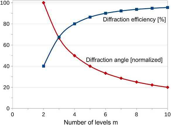
Italsohastobenotedthat,becausethelateral spacingbetweenthestepsis fixedbytheresolutionof theprocessorbythepixelpitchinthecaseofan LCoSLSM,themaximumgratingspacingachievable (L)isdividedbythenumberoflevelsusedtodefine theramp.Thisreductionofthegratingspacinglimits themaximumdiffractionangleachievablebythe diffractionpatternaccordingtotheBragg Eq.(1.13) In Fig.1.15,weplottedboththebehavioroftheefficiency,whichincreaseswiththenumberoflevels,and thediffractionangle,whichdecreaseswiththesame number.Thus,theuserisoftenconfrontedtoachoice inselectingeitherhighefficiencyorlargerdiffraction angle.
Althoughthefunctionof Eq.(1.54) iscontinuous,in therealworld, m canonlytakesdiscretevalues,starting at2. m ¼ 2isthecaseofabinarygrating,forwhich Eq. (1.54) logicallygivesthesamevalueofefficiency (40.5%)aswhencomputeddirectlyby Eq.(1.49), describingbinaryphasegrating.
FIG.1.15 Diffractionefficiencyandangleofadiscretized sawtoothgratingstructurewitha2p phasemodulation, accordingtothenumberoflevelsdefiningthesawtooth function.
Ithastobenotedthatthemodulationamplitudefor maximumefficiencyis DM ¼ 2for Eq.(1.54),and DM ¼ 1for Eq.(1.49),becauseduringthedigitization ofthemodulation,theaveragelevelismultipliedbya factoroftwo.
SCALARTHEORYOFDIFFRACTION
Nowthatwehaveseenthediffractionbyvariousperiodicgratings,wearegoingtogeneralizetheformalism foranystructure.Findingthemathematicalformulationforthetransformationbetweentheaperturegeometryandthediffracted fieldwillallowusnotonlyto determinetheformofthewavediffractedbyaspecific structurebutalsotocalculatethepatterntogeneratea particular field,theso-calledCGH.
Computingthediffractionpatternfromanobjector theretrievaloftheobjectfromtheobserveddiffraction patternisthe fieldofdigitalholography.Chapter5of thisbookisdedicatedtothesecomputations,andthe presentsectionismeantasanintroductiontothe field.
Digitalholographyoffersmanyadvantagescompared withregulardigitalphotography.Forexample,by capturingonbothphaseandamplitudeofthediffracted field,wecancomputethe3Dstructureoftheoriginalobject,changethefocusoftheinstrumentafterthedatahas beencaptured(postfocusing),orobservewavelength scaledeformationofanobject [39,40].
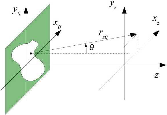
KirchhoffDiffractionIntegral Tostart,wewouldliketodeterminethepropagationof the fieldaftergoingthroughanarbitraryapertureas shownin Fig.1.16
FIG.1.16 Geometryanddefinitionofthecoordinate systemsforthepropagationoftheelectromagnetic field throughanaperture.
Theenergycarriedbythemagnetic fieldisusually muchweakerthantheenergyintheelectrical field (jBj¼jEj/c),sowearegoingtosimplifythecalculation bylimitingourselvestotheelectric field.
AccordingtotheHuygen’sprinciple,theaperture actsasahomogeneouslightsource,andthe fieldis nullintheopaqueportionsoftheaperture.So,atdistance z,the fieldisgivenbythesummationoverall thepointsoftheaperturemultipliedbythewavepropagationfunctiontothatdistance:
ThewavepropagationissolutionoftheHelmholtz equationintroducedin Eq.(1.1),andwewillchoose thesphericalwavesolution:
Inserting Eq.(1.56) Intoexpression1.55,weobtain the Kirchhoffdiffractionintegral:
where,forCartesiancoordinates: rz0 ¼ z2 þðxz x0 Þ2 þðyz y0 Þ2 q
FresnelDiffractionIntegral AselegantastheKirchhoffdiffractionintegral(Eq. 1.57)is,itisveryhardtocomputeandsomesimplificationsarenecessarytoobtainamanageableexpression.
Letusconsidertheexpansionofthe z termof the rz 0 expressioninTaylorseries: sqrt1 þ ε ¼ 1 þ
ε 2 ε2 8 þ .,suchthat: rz0 ¼ z þ 1 2 " xz x0 z 2 þ xz x0 z 2 # þ (1.58)
Our firstsetofapproximationswillbetoneglectthe thirdterminsidethecomplexexponential(exp(ikrz0)), andthesecondterminthedenominator(rz0)of Eq. (1.57).Thissetofsimplificationsisreferredasthe paraxialapproximationasitcanbeappliedforasmall apertureinregardtothedistance z:z [ xz x0 and z [ yz y0.
Thisleadstothe Fresneldiffractionintegral:
Theparaxialapproximationvaliditycriteria,usedto truncatetheTaylorseries,canalsobeexpressedasthe Fresnelnumber F:
whichisknownasthe Fraunhoferdiffractionintegral. Thisresultisparticularlyimportantonceitisrecognizedthattheintegrationtermissimplythe Fouriertransformoftheaperture.Furthermore,becauseitistheoptical intensitythatisrelevantformostapplications: I ¼jE2j, thephasefactorinfrontoftheintegralcanbeneglected. Ultimately,thislongmathematicaldevelopment leadstotheveryconvenientandelegantformulation:
ThecriteriafortheFraunhoferdiffractionintegralto bevalidisthattheobservationdistance z mustbemuch largerthantheaperturesizeandwavelength:
where D istheaperturediameter.
TheFresnelnumberinequality(Eq.1.60)expresses thefactthatthedistance z shouldbelargerthanthe wavelength l,butnotnecessarilymuchlargerthanthe aperture D.So,theFresnelapproximationisvalidin theso-called “ near field.”
FraunhoferDiffractionIntegral Ifweareinterestedbythesolutionforanobservation planefartherawayfromtheaperture,thatis,inthe “far field,” where z k x2 0 þ y 2 0 max ,furtherapproximationcanbeused.
IfweexpendthequadratictermsoftheFresnel diffractionintegral(Eq.1.59)as(a b)2 ¼ a 2
ðxz ; yz Þ¼ expðikz
Thequadraticphasefactorcanbesettounityover theentireaperture:
Thisconditionisknowninopticsasthe “far field” approximation.
DiffractionbySimpleApertures
ConsideringtherelativesimplicityoftheFraunhofer diffractionintegral(Eq.1.63),itispossibleto find analyticalsolutionsforsimpleaperturesilluminated byaplanewave:
Wearegoingtodevelopthecasesofthefollowing apertures:
• aslit
• acircularpinhole
• multipleslits
• aFresnelzoneplate
Diffractionbyaslit
Theslitisarectangularfunctionlocatedat z ¼ 0of width W alongthe x dimension:
Therefore, Eq.(1.61) canbewrittenas:
Theintegrationofthe fieldovertheslitisgivenby:
UsingEuler’sformula,wehave
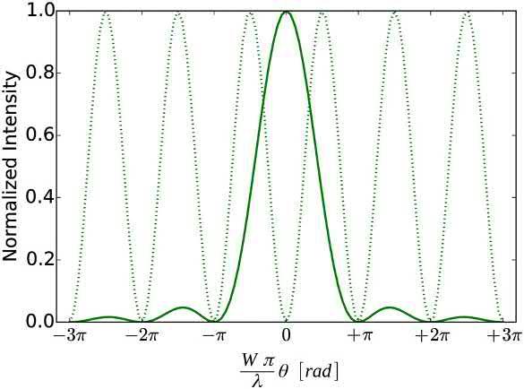
Or,incylindricalcoordinates(sinq ¼ x/z):
Becausetheintensitycanbeexpressedas: I]UU*
Theintensitydistributionof Eq.(1.71) isshownin Fig.1.17.
Diffractionbyacircularpinhole
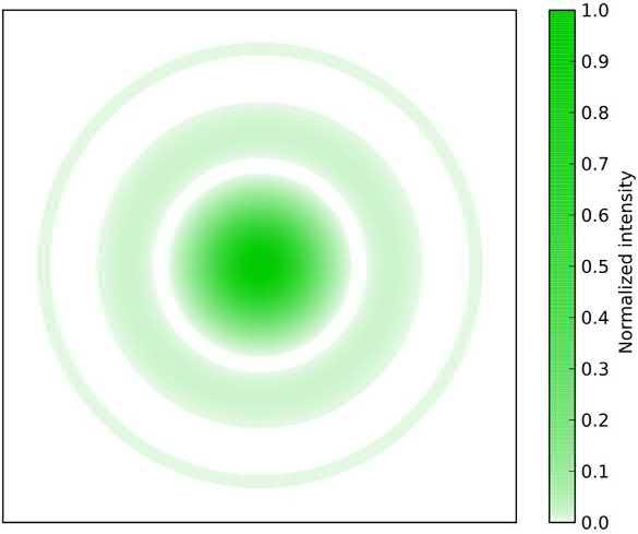
Thediffractionbyacircularapertureofdiameter D isa two-dimensional(2D)generalizationofthecaseofa slitwitharotationalsymmetryappliedtoit.Theintensitydistributioninthefar fieldbecomes
FIG.1.18 Diffractionpatternformedbyacircularaperture: theAirydisk.
Diffractionbymultipleslits
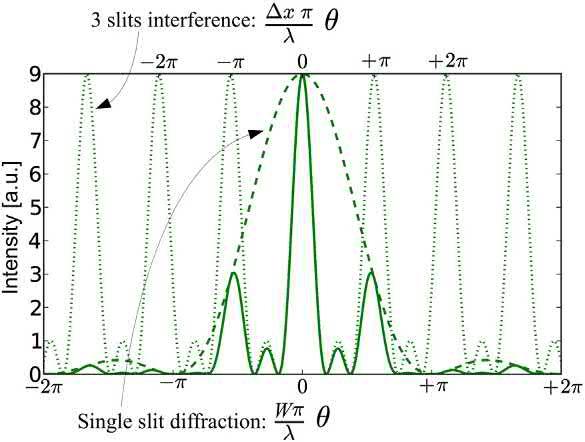
UndertheFraunhoferconditionexplainedin Section 3.3,theintensitydistributiondiffractedby m slitsof width W eachseparatedbyadistance Dx is
ThediffractionpatternformedbythepinholeapertureiscalledtheAirydiskandisshownin Fig.1.18 AcrosssectionofthisAirydiskpatternisasinc2 functionplottedin Fig.1.17
FIG.1.17 Interferencebyaslitofwidth W.Thedotedlineis asin2 functionforwhichsecondaryminimaarecollocated.
ThisequationcanbeobtainedbytheFouriertransformoftheapertureasexpressedin Eqs.(1.63)and (1.64 ).Alternatively,itcanbederivedbymultiplying theexpressionsforthediffractionbyasingleslit (whichgivesthe fi rsttermof Eq.1.73 )withtheinterferenceof m slits(whichgivesthesecondtermof Eq. 1.73).
Fig.1.19 showsanexampleofdiffractedintensity obtainedforthreeslits,withthedifferenttermsof Eq. (1.73) plottedindependently.
Fresnelzoneplate
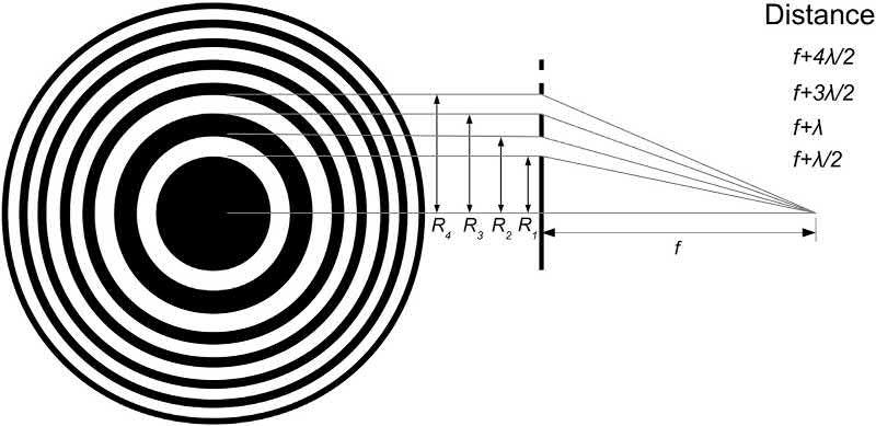
TheFresnelzoneplateisabinarystructurethatactsasa lens.Thezoneplatediffractstheincidentplanewave intoafocalspot.ThepatternofaFresnelzoneplateis comprisedofalternatingopaqueandtransparentrings thatactlikeslits.Theradii Rm oftheseringsissuch thattheinterferenceisconstructivealongtheaxisat thefocaldistance f:
FIG.1.19 Far fieldintensitypatternformedbythe diffractionfrom3slits(plainline).Thepatternisobtainedby multiplyingtheinterferenceof3slits(dotedline)bythe diffractionbyasingleslit(dashedline).
Fig.1.20 showsaFresnelzoneplatestructureandthe conditionontheradii Rm oftheringstoobtain constructiveinterferenceatadistance f,whichisthat thedistancefromtheradiitothefocalpointmustbe amultipleofhalfwavelength(ml/2).
Ithastobenotedthattheblackandtransparent ringscomposingtheFresnelzoneplatecanbeinverted withoutanyalterationinthediffractionproperties.
TheFresnelzoneplateisabinaryamplitudemodulationdiffractiveelement.Inthatregard,wehaveseen in Section2.4 onthingratingcharacteristicsthatsuch astructurediffractsmultipleoddorders.Inthecaseof thezoneplate,thepositivehigherorders(2m þ 1) willformmultiplefocalpointsat f/(2m þ 1),when thenegativeorders( 2m þ 1)willactas negativelenses withfocallengths f/(2m þ 1).
Toreducethenumberofhigherordersandconcentratetheenergyintofewerfocalspots,itispossibleto replacetheFresnelbinarymodulationpatternbyasinusoidalgrayscalemodulation.Suchagrayscalezone platewillonlydiffractintothe þ1and 1orders(see Section2.4).Toincreasethethroughputefficiencyof thezoneplate,itisalsopossibletoreplacetheamplitudemodulationwithaphasemodulation.
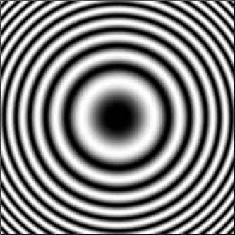
ThegrayscalezoneplateiscalledtheGaborzone plateandisshownin Fig.1.21.Theamplitudeofthe modulation M accordingtothedistancetothecenter r isgivenby:
with k ¼ 2p/l.
TheGaborzoneplatemodulationisthesameasthe oneobtainedbymakinginterfereaplanewavewitha collinearpointsourcelocatedatadistance f fromthe planeoftheinterferogram.Wewillseethisgeometry whendiscussingtheholographicrecordingsetupin Section6.
Zoneplatesareparticularlyinterestingtoobtainthin andlightopticalelementsthatcanreplacebulkyrefractivelenses.Morecomplexdiffractivestructurescanalso becomputed(i.e.,CGH),suchthattheyperformmore elaborateopticalfunctions.TheseCGHscanreplace asphericallensesthataredifficultandcostlytomanufacture.ZoneplatesandCGHscanalsobeusedto manipulateelectromagneticradiationsforwhichthere isnorefractivematerial,suchasforX-rays,orwhen therefractivematerialsaretooexpensive(chalcogenide glassesforthermalinfraredradiation).
Derivingtheshapeofanaperturetoobtainaspecific wavefrontinvolves findingtheinversefunctionofthe diffractionintegral.WecanuseeithertheKirchhoff
FIG.1.20 Fresnelzoneplatediffractivestructureandradiiofthesuccessiveringstoobtainconstructive interferenceatthedistance f.
FIG.1.21 Gaborzoneplatepattern:sinusoidalphaseor amplitudemodulationthatfocusesanincidentplanewave intoafocalspot.
(Eq.1.57),theFresnel(Eq.1.59),ortheFraunhofer(Eq. 1.63)diffractionintegrals,tocalculatethespecificaperturethatwillgeneratethedesiredwavefront.
Forthemostgeneralcase,anexactsolutionforthese equationscannotbefound,andthediffractionpattern (i.e.,theshapeoftheaperture)mustbecalculatedusing acomputer.The fieldofCGHsstartedinthelate1960s whenscientistsgainedgreateraccesstocomputers.The fieldexpandsrapidlywiththeimplementationofthe fastFouriertransform(FFT)algorithmthatmade possibletocomputeFouriertransformover22Dimages ofsignificantsize [17,18,41]
However,evenwithtoday’scomputers,itisnotyet possibletocomputeCGHsintheirmostrigorous form,usingtheKirchhoffdiffractionintegral,inreal time,forcomplex3Dimages.Thisproblem,known asthecomputationalbottleneck,canbegetaround usingsimplerexpressions(Fresnel,Fraunhofer)and byusinglookuptablesthatcontainprecalculated valuesfortheaperturetogeneratespeci fi cshapes andwavefronts [42 44] .TheoptimizationofthealgorithmstocomputeCGHisstillanactivetopicof researchtoday.
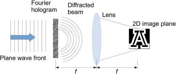
COMPUTER-GENERATEDHOLOGRAMS FourierHologram
Theeasiestpathforthecomputationofthediffraction patternistousetheFraunhoferdiffractionintegral (Eq.1.63)andtaketheinverseFouriertransformof eachsides:
thediffractionintegral.Thecommonshorthandfor theseconditionstoberespectedisthattheholographic imagewillbeformedatinfinity: z / N.Toobservethe imageatamoreconvenientdistance,onecanusealens whichwillformtheimageatitsfocallength.This configurationisshownin Fig.1.22
ConsideringtheFouriertransformof2Dfunctionis alwaysa2Dfunction,andthatthesolutionisindependentofthedistance z,thereisonlyoneimageplanefor theFourierhologramandtheimagewillbetwo dimensional.
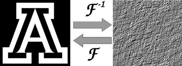
ExampleofaFourierbinaryamplitudehologramis shownin Fig.1.23
FresnelHologram
FindingtheinversefunctionfortheFresneldiffraction integral(Eq.1.59)issomewhatmorecomplicated thanfortheFraunhoferequationbecausethe field E is nowafunctionofthepropagationdistance z Eq. (1.59) canberewrittenbycreatingaparabolicwavelet functionsuchas:
Ofcourse,thesamefar fieldconditionsregardingthe imagedistancebeingmuchgreaterthantheaperture sizeandwavelengthapplytoboththisexpressionand
Bysubstituting h(z)in Eq.(1.59),itnowpossibleto findanexpressionfortheaperture:
FIG.1.22 Formationoftheimageatthefocalofalenswith aFourierhologram.
FIG.1.23 ExampleofaFourierholographicpattern(right) computedfroma2D fielddistribution(right).
FIG.1.24 ImageformationwithaFresnelcomputergeneratedhologram.
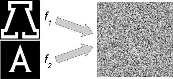
FIG.1.25 ExampleofaFresnelholographicpattern(right) computedfromatwo-fielddistributionlocatedatdifferent distances(right).
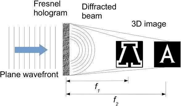
Eq.(1.78) iscertainlymoredauntingthanthe simplerFourierexpression1.76.However,thebenefit ofFresnelhologramisthatthereisnoneedtoinclude alensinthesetupinordertobringtheimagetoafocus, thediffractionpatterndoesthefocusingbyitself(see Fig.1.24).Theinclusionofthewaveletpropagation generatesFresnelzoneplate-likestructuresinthehologramthatactsasdiffractionlensestofocustheimageat finitelocations.
Inaddition,theimagegeneratedbytheFresnelhologramcanbethreedimensional,thatis,composedof severalfocalplanes.AnexampleofacomputergeneratedFresnelhologramisshownin Fig.1.25 where thetwosectionsoftheimagewillbeformedatdifferent distances.Acloseobservationofthediffractivepattern willrevealsomecentrosymmetricstructuresthatare duetotheFresnelzoneplates.
TheFresneldiffractionintegralequationcanalsobe usedtoreconstructanobjectwhenthehologram(or interferogram)iscapturedasanimage.TodayCMOS andCCDsensorshavepixelssmallenoughtoresolve theinterferenceproducedbysmallobjectslocated nearthesensorplane.Theadvantagesofnotimaging theobjectofinterestarethat, first,nolensisneeded,
andsecond,the3Dinformationcanbereconstructed. Thistechniquehasbeenusedtodemonstratevery high resolutionholographicmicroscopescapableof resolvingsinglecellssuchasredbloodcellsandlymphocytes [45].
IterativeComputationofHologram,the Gerchberg-SaxtonAlgorithm
Whencomputingadiffractionpatternfromanimage, orwhenreconstructinganimagefromadiffraction pattern(inversetransformation),theFouriertransform operationgeneratestwoterms:arealpart,whichisthe transmittance(amplitude);andanimaginarypart, whichisthephasemodulation.Quiteoftenoneor theotherisnotcapturedduringthemeasurement,or notreproducedduringthedisplayofthehologram. Thisisduetothepropertiesoftheimagesensor(amplitudeonly),orbecauseofthecharacteristicsofthe displayelement:LCoSSLMarephase-onlyelements, andDLPsareamplitude-onlyelements.Leftunaddressed,thisproblemreducestheefficiencyofthehologramandincreasesthenoiseintheimage.
Aneffectivewaytominimizethedegradationisto useaniterativecomputationsuchastheGerchbergSaxtonalgorithm [46].Theprincipleofthisalgorithm isthatthephase(intensity)ofthe mth iterationcan beusedalongthesourceintensity(phase)distribution tocalculatethe m þ 1stfunctionviaFouriertransform anditsinverse.Aschematicdiagramoftheiterationis shownin Fig.1.26 whereaphasehologramis computedfromtheimageintensitydistribution.Chapter3ofthisbookdevelopsthedifferentvariationsofthe Gerchberg-Saxtonalgorithmandtheirusefordifferent applications.
Forimagingpurpose,theGerchberg-Saxtonalgorithmconvergesquiterapidlyasitcanbeseenin Fig.1.27,whereonlythreeiterationsarenecessaryfor thehologramtoeliminatemostofthenoiseintheimageitreproduces.
However,forapplicationswherethenoiseneedsto bereducedtoaminimum,itcouldtakeseveraltens ofiterationstooptimizetheSNR [47].Foramore detaileddiscussionabouttheGerchberg-Saxtonalgorithmaswellasmoreadvancedcomputationaltechniques,seeChapter3byTomD.Milster.
ResolutionofComputer-Generated Holograms
ThelimitationintheresolutionofCGHcomesfrom severalfactors.The firstonebeingthecomputationof theFouriertransform,whichusuallyusesaFFTalgorithmthatsamplesthefunctionandlimitsthenumber offrequencies.Becauseofthissampling,theresultis