MagneticCommunications
TheoryandTechniques
ERWULIU
TongjiUniversity
ZHISUN
TsinghuaUniversity
RUIWANG
TongjiUniversity
HONGZHIGUO
NorfolkStateUniversity
ShaftesburyRoad,CambridgeCB28EA,UnitedKingdom
OneLibertyPlaza,20thFloor,NewYork,NY10006,USA
477WilliamstownRoad,PortMelbourne,VIC3207,Australia
314–321,3rdFloor,Plot3,SplendorForum,JasolaDistrictCentre, NewDelhi–110025,India
103PenangRoad,#05–06/07,VisioncrestCommercial,Singapore238467
CambridgeUniversityPressispartofCambridgeUniversityPress&Assessment, adepartmentoftheUniversityofCambridge.
WesharetheUniversity’smissiontocontributetosocietythroughthepursuitof education,learningandresearchatthehighestinternationallevelsofexcellence.
www.cambridge.org
Informationonthistitle: www.cambridge.org/9781108481670
DOI: 10.1017/9781108674843
© ErwuLiu,ZhiSun,RuiWang,andHongzhiGuo2024
Thispublicationisincopyright.Subjecttostatutoryexceptionandtotheprovisions ofrelevantcollectivelicensingagreements,noreproductionofanypartmaytake placewithoutthewrittenpermissionofCambridgeUniversityPress&Assessment. Firstpublished2024
AcataloguerecordforthispublicationisavailablefromtheBritishLibrary
ACataloging-in-Publicationdatarecordforthisbookisavailablefromthe LibraryofCongress
ISBN978-1-108-48167-0Hardback
CambridgeUniversityPress&Assessmenthasnoresponsibilityforthepersistence oraccuracyofURLsforexternalorthird-partyinternetwebsitesreferredtointhis publicationanddoesnotguaranteethatanycontentonsuchwebsitesis,orwill remain,accurateorappropriate.
Preface
Usingthenearfieldofacoiltotransmitasignalinsteadofpropagationwaves,magneticcommunicationturnsouttobeaneffectiveandreliablecommunicationapproach forextremelyharshenvironmentsthatarehostiletowirelesscommunicationssuchas sensornetworkingundergroundorunderwater.Magneticcommunicationtechnologies havenotonlythegreatsignificanceforthedevelopmentofcommunicationtheorybut alsothegreatpotentialforalargenumberofengineeringapplicationsintheInternet ofThings(IoT)era.
Theso-calledmagneticcommunicationmakesuseofthetime-varyingmagnetic fieldproducedbythetransmittingantenna,sothatthereceivingantennareceivesthe energysignalbymutualinductance.Researchesshowthatthepenetrabilityofamagneticcommunicationsystemdependsonthemagneticpermeabilityofthemedium. Becausethemagneticpermeabilityofthelayer,rock,ice,soil,andorebedisclose totheair,channelconditionsbringlesseffectstomagnetictransmissionthanelectrictransmission.Therefore,thecommunicationnetworkbasedondeep-penetrating magneticinduction(MI)canexpandtheperceptionabilityandsensingrangeofinformationtechnologyeffectively,whichcanbeappliedtocomplexenvironments,suchas underground,underwater,tunnel,mountain,rock,ice,andforest.Thesubjectiscurrentlyreceivinggreatscientificattention, andseveralimportantnewresultshavebeen recentlyobtained.Thisbookwillpresenta comprehensiveaccountofthisemerging field.
Thebookcomprisesthreeparts.
-PartI:IntroductionandPropertiesofMI
Twoinitialchapters(Chapters1–2)ofthispartgiveanintroductionabout magneticcommunications.Chapter1presentsthehistory,stateoftheart,and researchchallengesofmagneticcommunications.Chapter2brieflydiscussesthe differencesbetweenmagneticcommunicationsandotherwireless communications.Italsodescribessomebasicperformanceindicatorsofmagnetic communications.Thischapterconstitutesthereferencepointforappreciatingthe resultsthatMIholds.
Subsequently,twochaptersaredevotedtoantennatechnologyformagnetic communication(Chapter3)andchannelcharacteristics(Chapter4).
-PartII:TheoreticalBasis
Thispartmainlyexpoundsthetheoryofmagneticcommunicationfromdifferent aspects.Specifically,theMIconnection(Chapter5),networkperformance (Chapter6),andprotocolstacks(Chapter7)areanalyzed.
-PartIII:Applications
Thispart(Chapter8)discussescertainMIapplicationstovalidatethepreviously introducedtheories.
Recentyearshaveseenagrowingtrendintheapplicationofcommunication technologiesinextremelyharshenvironments.Magneticcommunicationisusually necessarywhenwewantreliablesignalpropagationthroughradio-frequency-hostile (RF-hostile)media.Inprinciple,magneticcommunicationiscomplementarytowirelesscommunications.Thisiswhyitisimportanttounderstandthefiguresofmeritof thecomponentsofamagneticcommunicationsystem,howtomodelthem,andhowto analyzethem.Moreover,withthefastpenetrationoftheIoTservicesintoRF-hostile environments,anin-depthunderstandingofmagneticcommunicationtechnologiesis highlydesired.Althoughseveralresearchpapersonmagneticcommunicationsare availabletodate,theavailableinformationisverylimited.Itistheappropriatetime tohaveareferencebookprovidingalltheinformationneededtounderstandmagnetic communicationsinasinglevolume.Werecognizethatasingle-volumebookcannot coveralltechniques,norisitourintentiontocovereverythinginonesinglebook. Instead,wehopethisbookwillserveourpurposeofofferingafirstcourseonthis importantandboomingsubjectofmagneticcommunicationsandwillraisetheinterest neededtotakemagneticcommunicationresear ch,development,andstandardization activitiestothenextlevel.
Thisbookwillbeofinterestforgraduatestudents,researchers,andelectricalengineersworkinginthefieldsofwirelessandtheIoT.Itwillprovideacomprehensive introductiontomagneticcommunicationfromacombinedtheoreticalandpracticalperspective,andthereadersareexpectedtohavebasicknowledgeinwireless communicationsandelectromagnetictheory.
1 Introduction
Asoneofthemostvibrantareasinthecommunicationfield,wirelesscommunication hasbeengoingthroughrapiddevelopment.Ontheotherhand,therehasbeenanexplosiveincreaseindemandfortetherlessaccessinmoreandmorescenarios.TheInternet ofThings(IoT),forinstance,isanimportantdevelopmentstageofinformationage. ThevisionofIoTistoachieve“InternetofEverything”;thekeytotherealizationof thegoalistobuildafullyconnectedmultiusernetworkthatcanbeappliedtodiversifiedcommunications.AsIoTapplicationsareextendingtomoreandmorescenarios, commonwirelesscommunicationtechniquesusingelectromagnetic(EM)wavesare becomingdissatisfactoryinbothcoverageandconnectivity.EMwavesexperience highlevelsofattenuationduetoabsorptionbyanaturalmedium,suchassoil,rock, andwater,whichleadstoitsinabilitytotransmitinsomechallengingenvironments (underground,deepmine,mountain,rock,ice,tunnel,underwater,forest, ...)aswell asrestrictionstothedevelopmentofIoT.
Toovercomethisdifficulty,deeppenetrationtechniques,suchasmagneticcommunications(MC),havebroughtsolutionstothesetransmissionproblems.Theso-called MCmakesuseofthetime-varyingmagneticfieldproducedbythetransmitting antenna,sothatthereceivingantennareceivestheenergysignalbymutualinductance. ResearchesshowthatthepenetrabilityoftheMCsystemdependsonthemagnetic permeabilityofthemedium.Becausethemagneticpermeabilityofthelayer,rock, ice,soil,andorebedisclosetotheair,channelconditionsbringlesseffectstomagnetictransmissionthanelectrictransmission.Therefore,thecommunicationnetwork basedondeep-penetratingmagneticinduction(MI)canexpandtheperceptionabilityandsensingrangeofinformationtechnologyeffectively,whichcanbeappliedto complexenvironments,suchasunderground,underwater,tunnel,mountain,rock,ice, andforest.WecanconcludethatthenetworkconstructionofIoTbasedonMCisof greatvalueandcanberegardedasoneofthereliabletechnologiestoimprovethe connectivityofawirelessnetwork.
Thedeep-penetratingMCtechnologyisbasedontheprincipleofmutualinductance ofthemagneticfield.Thealternatingmagneticfieldisgeneratedbythetransmittingcoil,andthereceivingterminalalsousesthecoilantennatomeasurethemutual inductanceofthetime-varyingmagneticfieldinthespacetoobtaintheinformation encodedinthetime-varyingsignal(Fig.1.1).InMCtechnology,inordertoachieve reliablelong-distancepenetratingtransmission,thesensitivityofthereceivingantenna isusuallyrequiredtoreachthepT(picoTesla)level.Inaddition,theperformance
optimizationofthetransmittercircuitin MC,antennadesign,andreceivingsignal noisefilteringareverychallengingtechnicalaspects.
FundamentalEMfieldandcircuittheoriesforMCareincludedinthischapter.AdvancedMCtheoryandlatestMIapplicationsarediscussedinthefollowing chapters.
1.1MagneticCommunicationandWirelessCommunication
Inthelasttwodecades,drivenbyawealth oftheoreticaldevelopmentandpractical requirement,manykindsofcommunicationtechnologiesunderdifferentsituations drewtheattentionofresearchcommunity.Atpresent,themainstreamcommunicationtechnologiesincludeacousticcommunication,opticalwavescommunication, EMwavecommunication,andMC.This chaptercoversthesubjectofthedifferences betweenMCandwirelesscommunication.
1.1.1TheComparisonbetweenMagneticCommunicationandOtherWireless Communications
Formostchallengingenvironmentsmentionedinthebeginning,therearenowirelesscommunicationsdeploymentattemptsbeforeIoTapplications.Ontheotherhand, otherwirelesscommunicationtechnologiesarenotabletoprovidereliablecoverageandconnectivityinsuchenvironments.Takeundergroundmineforexample, EM-wave-basedwirelesscommunicationcanonlysupportasemi-wirelesssystem, inwhichthelinksbetweenthesurfaceandundergroundarewired.Suchasystemis vulnerable,especiallyinadisastersituation.
However,inanunderwaterenvironment,manywirelesscommunicationtechnologieshavebeenstudiedforbothindustryandmilitarydemands.Themajorityofthe workonunderwatercommunicationismainlybasedonacousticcommunication, whileitexhibitshighpropagationdelaysalongwithverylowdatarates,andhighly
Figure1.1 Wirelessmagneticcommunication
Figure1.2 Communicationscenariosunderruggedenvironment environment-dependentchannelbehavior.Thehighlyenvironment-dependentchannelbehaviorinunderwatercommunicationiscausedbycomplexmultipathfading, prevalentDopplereffects,andsignificantvariationofthesepropertiesduetotemperature,salinity,orpressure[1].Opticalwavesdonotsufferfromhighattenuationbut experiencemultiplescatteringoflight,whichresultsininter-symbolinterferenceand shorttransmissionrange[2].Moreover,thetransmissionofopticalsignalsrequires highprecisioninpointingthenarrowlaserbeams.Traditionalwirelesscommunication techniquesusingEMwavesencounterthreemajorproblems:highpathloss,dynamic channelcondition,andlargeantennasize[3].EMwavesexperiencehighattenuation thatseverelylimitstheachievablecommunicationrange.Toincreasethecommunicationrange,largeantennasarerequiredfor low-frequencyEMcommunication,which isnotpracticalforsmallunderwatervehiclesandrobots.
Tosumup,thepenetrationabilityofthetraditionalapproachesisrelativelyweak, leadingtopropagationdifficultiesinachallengingenvironment,suchasunderground, deepmine,mountainarea,terrane,tunnel,underwater,andforests,asshownin Fig.1.2.
1.1.2BenefitsofMagneticCommunication
Magneticcommunicationisapromisingalternativetechniqueprovidingsolutions forthementionedproblems.Itutilizesthetransmittingantennastogenerateatimevaryingmagneticfieldsinthemedium,thus enablingthereceivingantennastoreceive theenergysignalinasenseofmutualinductance.OurresearchshowsthatthedielectricpenetrationperformanceoftheMCsystemdependsmainlyonthemagnetic conductivityofthemedium.
UsingMIcouldhaveseveralbenefits.Oneofthesebenefitsisthatdensemedia (suchassoilandwater)causelittlevariationintherateofattenuationofmagnetic fieldsfromthatofair,sincethemagneticpenetrabilityforeachofthesematerials isalmostthesame[4].Althoughgenerallyunfavorableforopen-aircommunication sincethemagneticfieldstrengthfallsfasterthanthatinEMwaves,thereductionin signallosscausedbypropagationthroughsoilcompensatesforthisintheunderground scenario.
AnotherfavorablepropertyofMIisthatsincethemagneticfieldisgeneratedin thenearfield,itisnon-propagating[4],whichmeansthatmultipathfadingisnota problemforMC.Moreover,sincecommunicationisachievedbycouplinginthenonpropagatingnearfield,atransmittingdevicecandetectthepresenceofanyactive receiversviatheinducedloadonthecoil.Thispropertymayprovidevaluableinformationforprotocols,actingasatypeofacknowledgementthatthetransmissionwas sensedbyaremotedevice.
InanMCsystem,theantennadesignisaccomplishedwiththeuseofacoilofwire forbothtransmissionandreception.Thestrengthofthemagneticfieldproducedby agivencoilisproportionaltothenumberofturnsofwire,thecross-sectionalareaof thecoil,andthemagneticpermeabilityofanymaterialplacedinthecoreofthecoil. TheuseofwirecoilsforMItransmissionandreceptionrepresentsasubstantialbenefitovertheuseofantennasforpropagatingEMwaves.Lowfrequenciesnecessary forthepropagationofEMwavesmeanthatlargeantennasarenecessaryforreasonableefficiency,whichobviouslyconflictswiththenecessitythatundergroundsensors remainsmall.
Wetaketheunderwaterscenario,forinstance,asshowninTable1.1.Althoughthe bandwidthoftheMIsystemissmallerthanthatoftheEMwavesystem,MCprovides alongertransmissionrange.MCalsohastheadvantagethatitsperformanceisnot influencedbythepropertiesofthemedium.
Basedontheadvantagesdiscussedabove,anMCnetworkcaneffectivelyexpand theawarenessandperceptionofthenetwork.Ithasagoodperformanceeveninsome harshscenarioswithmanynaturalmediumsormediumboundaries,suchasunderground,underwater,tunnels,massif,rockstratum,icelayer,andforest.TheMIsystem enablesareliableandstablecommunicationinsomechallengingenvironmentsinstead oftheEMsystem.
1.1.3ApplicationsofMagneticCommunication
DifferentfromthetraditionalEMcommunicationsystems,thetransmittingantennaof anMCsystemisequivalenttoamagneticdipole,whichalmostdoesnotgeneratean electricfield.Hence,theMIcarrierisnot apropagatingwave,anditcanberegarded asaquasi-staticmagneticfieldgeneratedintheair.So,theMIsignalsarefreefrom theinfluenceofmultipathpropagationcomparedwithordinarywirelesssignals.Due tothefactthatthepermeabilityofsoilandwaterisclosetothatofair,MIsignals
Table1.1 ComparisonofunderwaterMI,EM,acoustic,andopticalcommunications
CommunicationparadigmPropagationspeedDataratesCommunicationranges
MI3 33 × 108 m/sMb/s10–100m
EM3. 33 × 108 m/sMb/s ≤ 10m
Acoustic1,500m/skb/skm
Optical3. 33 × 108 m/sMb/s
CommunicationparadigmChanneldependencyStealthoperation
MIConductivityYes
EMConductivity,multipathYes
AcousticMultipath,Dropper, temperature,Audible pressure,salinity, environmentalsoundnoise
OpticalLightscattering,Visible line-of-sightcommunication, ambientlightnoise
caneasilypenetratemediumssuchaswater,sedimentlayer,androck.Therefore,MC enablemanyimportantapplications.
In[5],theauthorsintroducedMItechnologiestoawirelesssensornetworkfor undergroundpipelinemonitoring.ThisMCsystemcanprovidealow-costandrealtimeleakagedetectionandlocalizationtechniqueforundergroundpipelines.The authorsof[6]and[7]analyzedtheperformanceofanMCsystemunderwaterto measurebasiccommunicationmetrics,suchasthesignal-to-noiseratio,biterror rate(BER),connectivity,andcommunicationbandwidth.AnMCsystemcanalsobe appliedtoaddresstheissueofwatershortageconfrontingirrigation,whichwasstudiedin[8].Theauthorsof[8]usedtheMCnetworkforWirelessUndergroundSensor Networks(WUSN)insteadoftheEMwavecommunicationforWUSNtorealizean irrigationcontrolsysteminhorticultureinAustralia.Inadistrictheatingsystem,MC technologiesalsoplayabigroleincopingwiththechallengingundergroundchannel environmentdiscussedin[9].Inaddition,MCtechnologiescanbeofgreatbenefits inrescuingpeopleifthere’saminingdisaster,flooding,oracollapseofunderground tunnels[10].
Besidestheautomationandcommunicationapplicationspresentedabove,another importantapplicationofMCtechnologiesislocalization.MIlocalizationdoesnotrely onapropagatingwavebutgeneratesaquasi-staticmagneticfieldintheair.Thisdirectionhasdrawnmuchattentionrecently.Ateam attheUniversityofOxforddeveloped anMI-basedlocalizationsystemthatisshowninFig. 1.3 toprovide3Dlocalization in[11].Thisincrementallydeployedsystemcanquicklylocalizeachallengingundergroundscenariowithaccuracyaround1m.In[12],theMIsystemwasappliedto indoorlocalization.MIlocalizationhasahugeadvantagethatobstacles,suchaswalls, floors,andpeople,whichheavilyimpact theperformanceofEMwavesarealmost “transparent”totheMCsystem.However,theMIsystemhasitsowndrawback,i.e.,it
Figure1.3 MI-basedlocalizationsystem issensitivetomaterials.Byusingsignalprocessingandsensorfusionacrossmultiplesystemlayersagainstthesensitivitytomaterials,theMIlocalizationsystemcanget 3Dpositioningwithlocalizationerrorsbelow0.8meveninsomeheavilydistorted areas.
1.2Preliminaries
1.2.1PolarCoordinate
Polarcoordinatehasbeenfrequentlyusedinthisbook.AsshowninFig. 1.4,weuse er , eθ ,and eφ torepresentthreeunitcoordinatevectorsofapolarcoordinatesystem. Let ex , ey ,and ez betheunitcoordinatevectorsofarectangularcoordinatesystem. Thenwehavethefollowingrelationships:
1.2.2LoopAntenna
MCareaccomplishedwiththeuseofloopantennas.Asingle-turncircularloop antennaisshowninFig. 1.5 onthe x y planeat z = 0.Let a representtheradius ofthecoil.Letthewireisassumedtobeverythinandthecurrent I = I0 ,where I0 is aconstant[13].
Thentheradiatedfieldsofsuchaloopantennaatanarbitrarypoint N0 are approximatelyexpressedunderthesphericalcoordinateswiththemagneticfield components[13]:
whiletheelectric-fieldcomponents[13]:
where k = 2 π/λ
ThesignalenergyofMCistransmittedinanear-fieldregion,i.e., kr 1.With thisassumption,theexpressionsofthefieldsgivenby(1.2)and(1.3)canbesimplified as[34]:
Figure1.5 Circularloopantenna
1.2.3MagneticMoment
MagneticmomentisafundamentalmetrictomeasurethecapacityofanMIloop antenna;itismeasuredbythefollowingequation:
where A representstheareaofloop.Additionally,inastandardcircularloop,wehave A = π a2 .Inthiscase,themagneticmomentofaloopantennaof N turnsisgivenby
AnMIantennawithalargermagneticmomentcanradiateastrongermagneticfield signal.
InanMCsystem,themagneticfieldismeasuredinthe B-fieldwithSIunittesla (symbol: T ).Consideringaconstantvalueoftransmittingcurrent I ,wehavethefrequency f = 0and k = 0,andconsequently e jkr = 1.Themagneticfieldvectoratthe point N0 (Fig. 1.5)inauniformvacuumspaceis
Table1.2 Resistivity
Material
Carbon(graphene)1 × 10 8
Silver1. 59 × 10 8
Copper1. 68 × 10 8
Annealedcopper1 72 × 10 8
Gold2 44 × 10 8
Aluminum2 82 × 10 8
Tungsten5. 6 × 10 8
Iron9. 71 × 10 8
where μ0 = 4 π × 10 7 T · m/Aisthepermeabilityofvacuum.Hence,themagnitude of B is
Equation(1.9)revealsthat,foragivenrange r ,themagneticfieldstrengthisproportionaltothemagneticmoment m,whileforagivenreceivingmagneticfieldstrength threshold,thetransmittingrange r ∝ m1/3 .Weconcludethatthreewayscanbeapplied toimprovethemagneticfieldsignalandthetransmittingrangefrom(1.9):enlarging thearea A,addingloopturns N ,andincreasingtransmittingcurrent I .Althoughthe threeparameters A, N ,and I areproportionaltothemagneticmoment,theconsequent increasesofconsumingpoweraredifferent.
Thepowerconsumedontheantennaloopisdirectlyrelatedwiththecurrent I ,i.e., P ∝ I 2 .Ontheotherhand,increasesinthenumberofturns N andarea A leadtothe growthofthedirect-current(DC)resistance.AfundamentalwaytocalculatetheDC resistanceofaloopisPouillet’slaw
inwhich ρ istheresistivityoftheloopmaterial, lw = 2 π aN representsthetotalwire length,and Aw isthecross-sectionalareaofthewire.Weprovidetheresistivityof someconductivematerialsinTable 1.2.Usually,theantennaloopismadeofthewire followingtheAmericanWireGauge(AWG)standard,whoseresistanceperlength rangesfrom2 × 10 4 Ω · m 1 to3Ω · m 1 withdifferentwirediameter).Thus,wecan useresistanceperlengthtocalculatethetotalDCresistance:
Foracircularloop, lw = 2a π
Afterwefigureoutthecalculationofantennaresistance,wecanfindthatthenumberofturns N isproportionaltotheDCresistance.Ontheotherhand,thelooparea A isrelatedtothecircumferenceaswellasthetotallength: lw ∝ A0 5 .Giventhatthe
power P ∝ R,weconcludethatenlargingthelooparea A isthemostefficientwayto increasethemagneticmoment.AnormalizedDCpowerversusmagneticmomentis showninFig. 1.6.Themagneticmomentsvaryfrom1to100timesbychanging A, N , and I ,respectively.
ItshouldbenotedthatonlyDCresistanceandDCpowerareconsideredinthis section;inductiveresistanceandconductiveresistanceinthecaseofalternatingcurrent(AC)willbediscussedinChapter2.Staticmagneticfieldstrengthcanbetreated asafundamentalmeasurementoftheMIsignal.Themagneticfieldsensitivityisa keyparameterforareceiver,becauseadvancedMCtechnologiesareallbasedon thereceivingofthemagneticfieldsignal.However,thesensitivityperformanceofa receiverdependsonthetechnologiesofantennadesign,antennamanufacturing,and receivingcircuit,whichiscostlyandempirical.
1.3MutualInductanceCircuit
Inordertoanalyzethecommunicationperformance,amutualinductancemodelis usedaspresentedinFig. 1.7.Inthismodel,wetakethesignalfrequencyintoconsideration.Thismodelisabletohelpustofigureoutthepower-transmittingprocessin MC.Similartothewirelesspowertransport,anMCchannelevaluatedbyanelectric voltageischaracterizedbythefollowingequation:
Figure1.6 NormalizedDCpowerandmagneticmoments
Here UM istheinducedvoltageatthereceivingside,whichcanfurtherbeusedto derivethereceivingpowerinSection1.4, Us isthesourcevoltageatthetransmitting side, Rt and Rr aretheDCresistancesofthetransmittingloopandreceivingloop, respectively,while Lt and Lr representtheinductanceoftransmittingandreceiving coil,respectively. Cr and Ct arethecapacitancesthataredecidedbytheresonant signalfrequencygivenasfollows:
1.3.1Self-Inductance
Accordingtothedefinitionofinductance,weestablishthatacurrent I inthetransmittingloopproducesamagneticflux ΦB throughthecentralregionoftheloop.Withthe fluxknown,theself-inductanceisobtainedas[14]
Figure1.7 Equivalentmutualinductioncircuit
where L istheself-inductance, N isthenumberofloopturns, ΦB isthemagneticflux, and I isthecurrent.
Themagneticflux ΦB iscalculatedasfollows:
,
where l isthelengthnearthemiddleoftheloop, n isthenumberofturnsperlength, and A istheareaoftheloop.Themagnitude
where μ isthemagneticpermeabilityofspacemedium,andfromEq.(1.14),wehave
Foranidealloop,when n = N and l issetto0 5a [15],theself-inductanceof transmittingandreceivingloopis
1.3.2MutualInductance
Similartothecalculationofself-induction,weassumethatthecurrent I producesa magneticflux Φr throughthereceivingloop.Themutualinductanceofthetwoloops inFig. 1.7 isthenobtainedas
Sincethemutualinductanceisdefined underastaticsituation,weuseequation(1.8) tocalculatethemagneticflux Φr :
Asaresult,wehave
1.3.3SkinEffect
Becauseofthechangesinthemagneticfield,MCareinfluencedbytheskineffect[16]. ThealternatingmagneticfieldoftheMIsystemcausedanalternatingelectriccurrent
tobecomedistributedwithaconductivematerial,andtheelectriccurrentflowsmainly betweentheoutersurfaceandalevelcalledtheskindepth, δ .Theskineffectcanbe ignorediftheoperatingfrequencyislow,becausetheskindepthisverylargeand theconsequentEMfieldexistedanywhereinthemedium[16].However,fortheMI systemwithahighcarrierfrequencyofuptotensofmegahertz[15, 17], δ becomes muchsmaller,andtheEMfieldhasenoughstrengthwithinashortrangearoundthe MIloop,whichsignificantlyweakensthemutualinductionbetweenantennaloops.
Inordertomodeltheinfluenceofskineffect,weintroduceanadditionattenuation factor G tothemutualinductance[16].Theadditionattenuationfactor G isafunction ofdistance r betweentheantennaloopsandtheskindepth δ inthemedium.According tothemodelprovedin[18],wehave
Let and σ representthemediumpermittivityandconductivity,respectively;then theskindepth δ canbycalculatedby[19]
Althoughtheskineffectisaccuratelycharacterizedby G ( r ,δ ),equation(1.22)is notfavorableinmostapplications.Therefore,ithasbeenapproximatedbasedona numericalmethodbyanexponentialfunction r δ in[16]:
FortheMCchannel,theskineffectleadstoadeclineinthemutualinduction betweentwoantennacoilsexpressedasfollows:
TheMIsignalpenetratesanundergroundandunderwaterlossymediummuchmore efficientlythanEMwaves[20].However,theimpactofthemediumisnon-ignorable. ExistingMIresearchismainlybasedonasimpleenvironment,suchasasingleuniformmediumspaceoranunderwaterenvironmentwithsurfacereflectionandlateral waves[20].StatisticalchannelsforacomplexenvironmentlikeaRayleighfading channelarelacked.
Conductivity
Conductivitymeasuresamater ial’sabilitytoconductanelectriccurrent.ItiscommonlyrepresentedbytheGreekletter σ .Theconductivityofamaterialoftenvaries
Table1.3 Conductivity
MaterialConductivity σ ( S/m )at20 ◦ C
Carbon(graphene)1 00 × 108
Copper5. 96 × 107
Aluminum3. 50 × 107
Calcium2 98 × 107
Seawater4. 80
Drinkingwater5 00 × 10 4 to5 00 × 10 2
Deionizedwater5 50 × 10 6
Silicon1 56 × 10 3
Air3. 00 × 10 15 to8. 00 × 10 15
Table1.4 Permeability
MaterialPermeability μ ( H /m )Relativepermeability μ μ 0
Vacuum4 π × 10 7 ( μ 0 )1
Air1 25663753 × 10 6 1.00000037
Water1 256627 × 10 6 0.999992
Concrete(dry)4 π × 10 7 1
Aluminum1 256665 × 10 6 1.000022
Platinum1. 256970 × 10 6 1.000265
Wood1. 2566376 × 10 6 1.00000043
Copper1 256629 × 10 6 0.999994
withdifferentfactors,includingtemperature, purity,andconcentrationofwaterthat containsdissolvedsalts(theconductivityofsomecommonmaterialscanbefound inTable1.3).Inaradiofrequency(RF)-challengedenvironment,thetransmission mediumismostlyanonconductivematerial.However,therecanbeanonnegligible levelofconductivityduetohumidityandmineralsubstances.
Permeability
Determiningthepermeabilityofacoalmineisacomplexproblem;therelativepermeabilityofcoaltogasandwaterdependsonthenatureofgas,theoperationalpressure, andfluid–mineralinteractions(thepermeabilityofothercommonmaterialscanbe foundinTable1.4forreference).
1.3.5Metamaterial
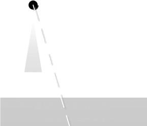
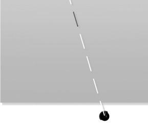
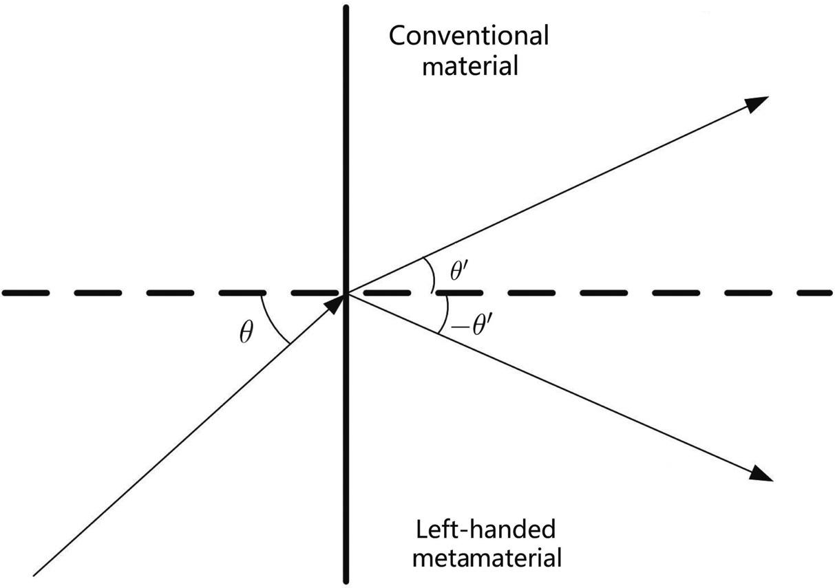
MetamaterialsforEMwaveshaveunusualphysicalfeatures,suchasthenegative refractionindex,includingpermittivity ε andpermeability μ.Toachieveacertain refractiveindex,metamaterialsarecarefullybuilttohaveasmallerstructurefeature thanthewavelengthoftherespectiveEMwave.Anegativerefractionindexisan importantcharacteristicofmetamaterialstodistinguishthemfromnaturalexisting materialsasillustratedinFig.1.8.
Figure1.8 Negativerefractiveindexofmetamaterial
ApplicationofMetamaterials
Metamaterialsarewidelyusedindifferentkindsoffields.Forexample,MRIcanbe enhancedusingmetamaterials.Long-TermEvolution(LTE)handsetsdeploymetamaterialsforantennaarray.Metamaterialscanalsobedeployedinmagneticcommunicationstoenhanceboththewirelesscommunicationsusingpoint-to-pointMIandMI waveguide.ComparedtoEMwave-basedcommunication,MIcaneasilypenetratethe lossymediuminRF-challengingenvironments.Onemajordrawbackisthelimited transmissiondistanceduetothefastattenuationofmagneticfields.Thetechniquesto enhancemagneticfieldsusingmetamaterialswillbediscussedlater.
1.3.6WaveguideStructure
ThetransmissiondistanceofanMIsystemsuffersfromfastpathlossdespiteitsrelativelystablechannelconditioncomparedtotheEMwave.Tothisend,awaveguide structureusingseveralpassiverelaydevicesisemployed.Therelaypointisusuallya simplecoilthatinducesasinusoidalcurrentinthenextcoilandsoonuntilitpasses tothereceivernode.Hence,therelaypointneedsnoenergysourcesorprocessing devices.Thewaveguidesystemisillustratedin[17]andtheequivalentcircuitdiagram ofwhichisshowninFig.1.9.
Weassumethatthewaveguidestructureusesthesametypeofcoilswiththesame parameters.Tobespecific,welet L bethecoilself-induction, M bethemutualinductancebetweenadjacentcoils, Ut bethevoltageofthetransmitterenergysource, R be thecopperresistanceofthecoil, C bethecapacitorloadedineachcoil,and ZL bethe loadimpedanceofthereceiver.Therearetotally( k 1)passiverelaysthatareplaced equidistantlybetweenthetransceivers.