
https://ebookmass.com/product/integrated-lasers-onsilicon-1st-edition-charles-cornet/
Frank H Netter
https://ebookmass.com/product/atlas-of-human-anatomy-by-frank-hnetter-seventh-edition-frank-h-netter/
ebookmass.com


https://ebookmass.com/product/integrated-lasers-onsilicon-1st-edition-charles-cornet/
Frank H Netter
https://ebookmass.com/product/atlas-of-human-anatomy-by-frank-hnetter-seventh-edition-frank-h-netter/
ebookmass.com
Advanced Lasers Set coordinated by Pierre-Noël Favennec, Frédérique de Fornel, Pascal Besnard


First published 2016 in Great Britain and the United States by ISTE Press Ltd and Elsevier Ltd
Apart from any fair dealing for the purposes of research or private study, or criticism or review, as permitted under the Copyright, Designs and Patents Act 1988, this publication may only be reproduced, stored or transmitted, in any form or by any means, with the prior permission in writing of the publishers, or in the case of reprographic reproduction in accordance with the terms and licenses issued by the CLA. Enquiries concerning reproduction outside these terms should be sent to the publishers at the undermentioned address:
ISTE Press Ltd
27-37 St George’s Road
Elsevier Ltd
The Boulevard, Langford Lane London SW19 4EU Kidlington, Oxford, OX5 1GB UK UK
www.iste.co.uk
www.elsevier.com
Notices
Knowledge and best practice in this field are constantly changing. As new research and experience broaden our understanding, changes in research methods, professional practices, or medical treatment may become necessary.
Practitioners and researchers must always rely on their own experience and knowledge in evaluating and using any information, methods, compounds, or experiments described herein. In using such information or methods they should be mindful of their own safety and the safety of others, including parties for whom they have a professional responsibility.
To the fullest extent of the law, neither the Publisher nor the authors, contributors, or editors, assume any liability for any injury and/or damage to persons or property as a matter of products liability, negligence or otherwise, or from any use or operation of any methods, products, instructions, or ideas contained in the material herein.
For information on all our publications visit our website at http://store.elsevier.com/
© ISTE Press Ltd 2016
The rights of Charles Cornet, Yoan Léger and Cédric Robert to be identified as the authors of this work have been asserted by them in accordance with the Copyright, Designs and Patents Act 1988.
British Library Cataloguing-in-Publication Data
A CIP record for this book is available from the British Library Library of Congress Cataloging in Publication Data
A catalog record for this book is available from the Library of Congress ISBN 978-1-78548-062-1
Printed and bound in the UK and US
x Integrated Lasers on Silicon
and C. Killian from French Institute for Research in Computer Science and Automation (INRIA) with whom integration strategies were widely discussed. We also thank our partners from the OPTOSI ANR Project No. 12-BS03-002-02, especially E. Tournié, J.-B. Rodriguez and L. Cerutti from Institut d’Electronique et des Systèmes (IES), F. Lelarge (Alcatel-III-V Lab) for the fruitful discussions about the integration constraints of lasers on silicon and B. Corbett (Tyndall National Institute) for the discussions about the bonding approaches. Support from “Region Bretagne” is also acknowledged. We finally want to thank all the members of the Optical Functions for Information Technologies (FOTON) laboratory, and especially the researchers from the Optoelectronics, Heteroepitaxy and Materials (OHM) research group of the Institut National des Sciences Appliquées de Rennes (INSA), who made this publication possible. Overall, this book benefited from the constant support of key people – Astrid, Emilie, Clémentine, Lise, Madée and Eilie.
Charles CORNET
Yoan LÉGER
Cédric ROBERT
April 2016
In this chapter, we provide a comprehensive overview of the ultimate properties and performances needed to truly achieve very large-scale integration of laser sources on a silicon chip. Toward this aim, the basic principles of CMOS microprocessors and the different integration schemes of a photonic layer into such architectures are first explained. Then, very simple aspects of semiconductor lasers are presented to provide the minimum prerequisites to the discussion in the next chapters. Finally, an assessment of the required quality that an integrated laser source should ideally possess is given.
The Sparc M7 microprocessor, announced by Oracle in late 2015, shows a record transistor count of 10 billion [AIN 15]. The smallest elements on the chip, the so-called technological node, are 20 nm large and are organized into height clusters of four cores. Thirteen layers of metallization ensure the interconnections between the cores, clock and power drive. We have come a long way from the first integrated circuit developed by Kilby roughly 60 years earlier, which contained two transistors only [KIL 76]. Nowadays, the architecture of microprocessors (MPs) has become so complex that limitations of the complementary metal oxide semiconductor (CMOS) technology progressively reveal themselves. We will see in the following that the
major concern of MP designer is presently energy, leading researchers to work on architecture solutions going beyond CMOS. Many leads are explored, from carbon nanotube electronics and spintronics to MP hybridization. In the last case, the introduction of different hardware technologies within a MP gambles on the complementary advantages of information technologies and high yield conversion between different information technology (IT) platforms or computation paradigms. The grand challenge of integrated photonics is to demonstrate the mandatory role that it could play in future generations of microprocessors, for data routing or even specific computation tasks.
This first section is a brief survey of present CMOS MP technologies and their challenges. The interested reader is encouraged to refer to dedicated books for a deeper understanding of microprocessor technologies, such as the Weste and Harris CMOS VLSI Design [PEA 16].
Very briefly, the architecture of CMOS microprocessors can be described as a silicon substrate or silicon on insulator (SOI) substrate, on which the logic components of the circuitry are processed, i.e. p- and n-type transistors, inverters, etc. Ion implantation and doping diffusion are mainly used to create the good and active layers of the transistors directly into the silicon. On the contrary, the gate oxide and polysilicon parts are deposited onto the substrate. The CMOS components are then connected through multiple metallization layers embedded into silicon dioxide. Transistor processing occurs at the beginning of the production line in the fab. It is called the “front-end of line” process while the final metallization is called the “back-end” process. By extension, front-end and back-end sometimes characterize positions within the chip, as we will see later. A fab line is generally developed for a single technological node as defined by the International Technology Roadmap for Semiconductors (ITRS). For microprocessors, the technological node refers to the lateral size of the
Abstraction levels
System level
Logic & circuit level
Layout level
Physical level
Related issues
• sub-system connections
• external interface
• correctness of elementary operations
• simplicity and elegance
• component co-integration
• process compatibility
• interaction between upper and lower levels
• speed
• total power
• signal reliability
Figure 1.2. Abstraction levels of a microprocessor design and related issues
In a microprocessor, the delay basically defines how fast memories are accessed, logic operations are executed and how long signals take to propagate through the chip. In the chip design, this has consequences for each abstraction level. At the physical level, the design of the transistors fixes their RC behavior and thus their dynamics. At the layout level, parasitic capacitances can be avoided by folded geometries where diffusion parts of transistors are shared. Moreover, below the 180 nm technological node, the RC delay related to interconnects exceeds the gate delays. Skin effects and crosstalks between wires also play a detrimental role. At the logic and circuit level, an analysis method called “logical effort” allows designers to choose the best logic function or number of inputs to a specific gate in order to minimize delays. Finally, at the system level, knowing the delay information obtained at lower abstraction level, decisions on the
al 20 lev de m co ha hi str di CM di lo al di on ex ca di
Integrated La
sers on Silicon
gorithm desi 00s, improv el where d lays decreas icro-architec mmercialize
gn of the ch ements in M esigns starte ing at fixed ture soluti d (see Figur
ip have to b P designs d to be pow clock frequ on and m e 1.3).
be taken. Esp brought clo wer-compelle encies, paral multicore M
ecially, in th ck frequenc d. In order lelism was t Ps started

Figure 1


From [D Inc. fig
Indeed, by d met the 1 ghly correlat ong compli
.3. Historical e AN 12] © 20 Reprinted by ure, please s 2004, power 00 W mark.

volution of th 12 Association permission. F ee www.iste.c

he microproces n for Computin For a color ver co.uk/cornet/la
consumptio
ed with the cations arise
ssipation in OS logic ssipation in ad capacities so generated ssipation is ly be decre ample, SO pacitances, ssipation. St
MPs has dy layer and o CMOS com as transistor when tran directly asso ased by a c I-based CM induces bo ill, below the
The trade-o technologic to develop namic and bviously cir es from the gates switch sistors are ciated with lever design OS, throug th shorter 90 nm nod
on of the mon off between cal node. Fro p power-effi static origin rcuitry-relate charging and h. Some shor partially “ the comput n of the log gh the low delays an de, the dynam
sor frequenc g Machinery, sion of the sers.zip o-core archi power and m the 45 nm cient chips. s coming fr d origins. D discharging t circuit curr on”. This d ation tasks a ic componen ering of p d lower d ic dissipatio
he early cies at a to keep the only to be cy, , itectures delay is m node, Energy from the Dynamic g of the rents are dynamic and can nts. For parasitic dynamic on is not
Laser Integration Challenges 9
organizations such as Intel and Luxtera [BOW 89]. However, introducing the less mature functional layer at the end of the process line also generates costly risks of chip degradation, even if photonic components can be tested formerly. Finally, the front-side integration scheme prevents fast communication between the CMOS logic and the photonic layer since the last metallization layers are the slowest ones.
The second integration scheme is the (combined) front-end integration. In this case, the photonic components are processed in the vicinity of the CMOS components. Such a scheme has been chosen by IBM because many building blocks of photonic integrated circuits are compatible with CMOS process and are mature on the silicon platform at telecom wavelengths. This is the case of Si waveguides, Si modulators and Ge photodetectors [ASS 12]. The monolithic integration approach is particularly appealing with this integration scheme, but we will see later that the monolithic front-end integration of a laser source is particularly challenging. This is clearly the present technological bottleneck for this approach. In addition, the combined front-end integration is certainly the integration scheme where most design abstraction levels will undergo modifications, from the physical to the system level. Still, the front-end integration schemes show many advantages and could be seen as the ultimate photonic integration scheme [BAE 12]. It offers favorable thermal management for both the photonic layer and CMOS as long as bulk Si substrates are used, fast interactions between the logic and optical routing components, and it could even limit test costs with an early introduction of the less mature photonic technology in the process line.
Finally, a third option for photonic integration consists in integrating the photonic layer at the back side of the substrate. In this case, so-called through silicon vias (TSVs) should be used to drive the photonic layer, preventing fast communication with the CMOS layer. However, this scheme could show advantages for thermal management and off-chip optical interfacing. Coupling with the heterogeneous integration approach should keep the process-line quite simple since the photonic layer will most likely be implemented at the end of the wafer process. However, using the back-side integration scheme with monolithic devices would require two-sided wafer process [DEB 98].
signal created by the initial spontaneous emission, through a stimulated emission process, and (2) a resonant optical cavity, which confines the electromagnetic radiation through the optical modes. The gain medium is generally composed of semiconducting materials, which are expected to provide efficiency, reliability, stability over the years, and an industry-compatible realization scheme.
The physical properties of semiconductors are usually summarized by giving their energy diagram, or “bandstructure” (see Figure 1.6 for an illustration). This gives the allowed energies for an electron, or a missing electron (a “hole”) as a function of its wavevector. A photon emission may occur when an electron in the conduction band (at higher energy) recombines with a hole in the valence band (at lower energy), the energy (and therefore the wavelength) of the photon being roughly equal to the energy difference between the conduction and the valence bands, often referred as the “bandgap energy.”
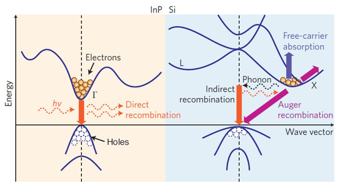
Figure 1.6. Energy band diagrams and major carrier transition processes in InP and silicon crystals, reprinted by permission from Macmillan Publishers Ltd: Nature Photonics, from ref [LIA 10] copyright 2010. In a direct bandgap structure (such as InP, left), electron–hole recombination almost always results in photon emission, whereas in an indirect band structure (such as Si, right), free-carrier absorption, Auger recombination and indirect recombination exist simultaneously, resulting in weak photon emission
This recombination must satisfy the momentum conservation rule. This means that the wavevector of the electron must be equal to the
wavevector of the hole in absolute value (because the momentum of the photon is generally negligible). In other words, the minimum of the conduction band must coincide with the maximum of the valence band. This is the case for direct bandgap semiconductors (usually at k = 0, in the so-called Г-valley) for which electron–hole radiative recombination is very efficient. Most III–V semiconductors are such direct bandgap semiconductors and are thus considered as ideal systems for semiconductor laser devices. On the other hand, in indirect bandgap semiconductors, the minimum of the conduction band does not coincide with the maximum of the valence band (for example, when the valence band maximum is in the Γ-valley whereas the conduction band minimum is located at a non-zero wavevector state such as the X-valley or L-valley). The electron–hole recombination requires an additional particle (generally a phonon) to satisfy the momentum conservation rule. Such a three-particle process is much less efficient and generally leads to weaker emitted light. It is especially the case in silicon (close to the X-valley), germanium (Lvalley) or in GaP (conduction band minimum in the X-valley), which makes these materials not naturally suited for optical emission.
A crucial condition for lasing is known as population inversion. When a gain medium is sufficiently pumped, electrically or optically, the population in the excited state of the lower-energy optical transition becomes larger than the population in the ground state. Emission becomes more likely than absorption and amplification occurs; the dominant emission process is the stimulated emission and the medium shows positive gain. In semiconductor active materials, population inversion is called the Bernard–Duraffourg condition and takes into account both the electron and hole populations in the conduction and valence bands respectively. Optical amplification then occurs when the quasi Fermi level energy difference becomes larger than the transition energy [BER 61]. In a laser, the optical cavity imposes a feedback mechanism to light amplification. The cavity is also an important (and necessary) source of optical losses in the laser device, due to the limited reflectivity of the mirrors that constitute it. It also enhances the light–matter interaction and provides wavelength selectivity through the appearance of confined optical modes. The
laser threshold is reached when gain overcomes the optical losses (mirror reflectivity, spontaneous emission, non-radiative recombinations) for a given confined mode. A strong coherent light emission is then observed from this mode, leaking out of the finite reflectivity mirrors. By contrast, the light emitted by the device below threshold, which spreads across all the available modes, is incoherent since spontaneous emission still dominates. The laser threshold is observed when plotting the output optical power of the laser as a function of the electrically or optically injected carriers and consists in a non-linear “kink point” in the optical power dependence. The slope of the curve after threshold is called differential quantum efficiency and is as important as the laser threshold itself to define the best operation point of a given laser source in terms of energy efficiency. As an example, lasers designed for strong output powers often show higher laser thresholds and much larger differential quantum efficiencies than low power lasers.
As shown in Figure 1.7(a), in the case of optically pumped lasers, electrons are photo-excited by an external laser beam, and therefore the threshold behavior is evidenced by plotting the output power as a function of the optical surface power density of the pumping laser. In some specific cases (pulsed operation), the optical excitation is sometimes expressed in energy per pulse, or as a fluence (laser pulse energy per unit area). Optical injection is an important tool to assess the properties of the gain medium and of the optical cavity in terms of structural quality and optical efficiency prior to the development of elements required for electrical injection of carriers (contact, diode design, doping etc.). Different injection conditions can be obtained by tuning the excitation wavelength in order to address specific carrier dynamics issues. Optical injection is thus of great importance for exploratory approaches, which will be discussed intermittently in the next chapters. But it remains a development tool for integrated lasers, which are expected to be driven by co-integrated electronics at the end.
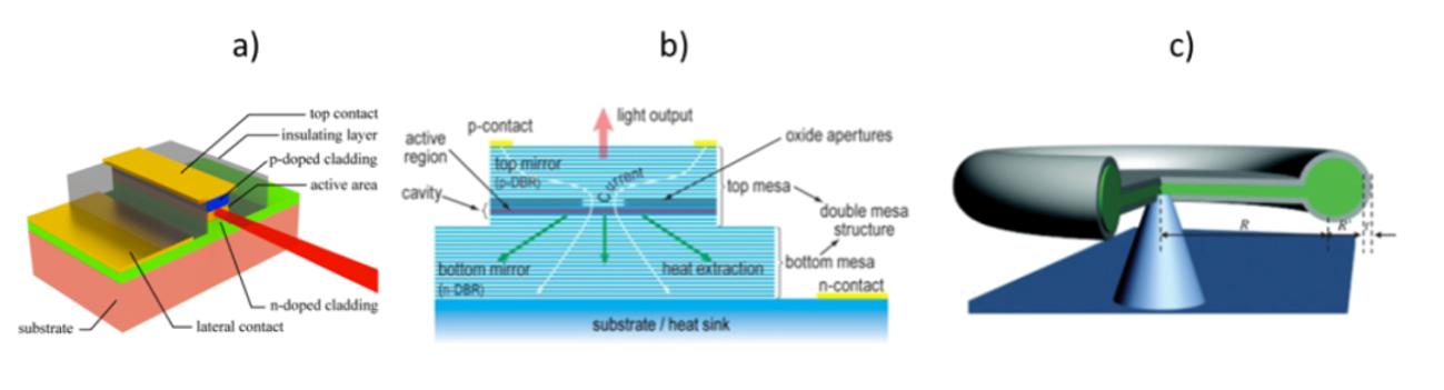
Figure 1.8. a) Conventional edge-emitting laser geometry, b) Example of a vertical cavity surface emitting laser device [WOL 12]. Reprinted with permission of SPIE. c) Example of a microresonator, allowing the propagation of whispering gallery modes. Reprinted with permission from [XIA 10]. Copyright 2010 by the American Physical Society
Another common strategy is the development of vertical cavity surface-emitting lasers (VCSELs). In these devices (schematically represented in Figure 1.8(b)), the vertical cavity is designed through distributed Bragg reflectors (DBR), an alternation of semiconductor layers with different optical indices, allowing the selection of a single or a few optical modes [MIC 12]. More recently, microresonators with a large variety of designs were proposed (see Figure 1.8(c)), from whispering gallery modes (WGM) resonators to photonic crystal cavities. In the first case, the electromagnetic waves propagate along the external edges of the device, forming a ring cavity [HEE 08]. On the contrary, photonic crystal cavities offer the strongest optical confinement of all integrated optical cavities, by confining light in all directions at the scale of the wavelength [PAS 13].
For any of these cavity geometries, confined optical modes (Fabry Perot, WGMs, etc.) occur when the cavity full path is equal to an integer multiple of the wavelength. Optical losses induced by the limited mirror reflectivity, scattering losses and parasite absorption allow to define for each confined mode the modal photon cavity lifetime, i.e. the typical time a photon “spends” into the cavity [SVE 12]. A more common approach in semiconductor lasers is the use of the cavity quality factor or Q-factor, which is the number of oscillations of the field before the circulating energy is decreased by a factor 1/e. Thus a high value of cavity Q implies low losses of the resonant system. In CMOS-compatible WGM micro-resonators,
Q-factors well above 108 have been demonstrated [LEE 12b]. The situation is different in typical edge lasers and VCSELs where Q-factors are around 102 and 103 respectively. The use of high Q-factors is interesting especially when the optical gain of the active area is relatively small, which is the case of some of the materials presented in the next chapters and where low optical power and lowenergy budget are needed for an integration architecture design. Finally, the small size of recently developed microcavities greatly enhances the integration potential in a photonic integrated circuit. Unfortunately, reducing the footprint of a laser source also makes electrical injection schemes more challenging.
The semiconductor laser operation principle and the concept of resonant optical cavity were discussed in the previous parts. It was shown that lasing only occurs when enough electrons (holes) are present in the conduction (valence) band of the active area, the socalled Bernard–Duraffourg (B&D) condition. If optical injection provides some degrees of freedom on the excitation conditions (excitation wavelength, injection power, even polarization) to reach such a regime, electrical injection is considered as a supplementary technological bottleneck in the realization of an integrated laser, raising new issues on the laser design.
First, the laser has to be contacted with metallic connections. Injecting current efficiently through a metal–semiconductor interface is not that easy. The Schottky barrier has to be overcome. With a welldefined succession of metallic layers and annealing steps, an ohmic contact with a low-access electrical resistance can be achieved. It is sometimes proposed to lower the bandgap and increase the doping levels of the surface semiconductor layers to facilitate the current injection. While these processes have been developed and optimized for years with silicon or conventional III–V semiconductors such as InP or GaAs, it is not always the case with the new approaches or
materials, which will be presented in this book, and especially the materials with large bandgaps.
Then, at the heart of the semiconductor laser injection is the p–n junction, which is formed by bringing into contact a p-doped and an n-doped semiconductor [AGR 12, SZE 12]. In this configuration, their quasi-Fermi levels equalize through the diffusion of electrons from the n-side to the p-side (and the opposite for holes), forming a depletion region at the p–n interface, where the gain medium is present [KRO 63]. When a direct bias is applied to the diode, electrons and holes massively enter this central region from each side respectively, locally fulfilling the B&D condition in the gain medium. The gain region is often non-intentionally doped to limit the free carrier absorption (see next parts). Here again, while the electronic transport through the p-i-n structures is well known, material research maturity is mandatory to control n- and p- doping levels, as well as nonintentional doping levels, which are critical parameters for efficient carrier injection.
Moreover, once injected into the semiconductor, both electrons and holes should not face any prohibitive potential barriers inside the semiconductor device, related to the complex material sequence imposed by both electrical injection issues (p-i-n junction) and optical confinement (core/cladding sequence, DBRs, etc.). Once carriers have reached the active area, they should even be blocked to form a charge carrier reservoir. This general issue is known as band engineering. This is illustrated in Figure 1.9, with the metamorphic InP-based quantum wells (QWs) laser structure from [GU 15]. Here, the electrons are injected in the conduction band by the n-doped InAlAs region (also serving as cladding layer for the optical confinement). They fall down in the InGaAs-active area, and they are finally trapped by InAs/InGaAs quantum wells where they can recombine with holes. Any electron that could escape these quantum wells would be blocked by the potential barrier induced by the p-doped InAlAs. The situation is similar for holes injected in the valence band.