HighPowerImpulseMagnetronSputtering: Fundamentals,Technologies,Challengesand Applications1stEditionDanielLundin
https://ebookmass.com/product/high-power-impulse-magnetronsputtering-fundamentals-technologies-challenges-andapplications-1st-edition-daniel-lundin/
Instant digital products (PDF, ePub, MOBI) ready for you
Download now and discover formats that fit your needs...
High Power Microwave Sources and Technologies Using Metamaterials 1st Edition John W. Luginsland (Editor)
https://ebookmass.com/product/high-power-microwave-sources-andtechnologies-using-metamaterials-1st-edition-john-w-luginsland-editor/
ebookmass.com
Nanotechnology in Paper and Wood Engineering : Fundamentals, Challenges and Applications Rajeev Bhat
https://ebookmass.com/product/nanotechnology-in-paper-and-woodengineering-fundamentals-challenges-and-applications-rajeev-bhat/
ebookmass.com
Power System Protection: Fundamentals and Applications (IEEE Press Series on Power and Energy Systems) 1st Edition Ciufo
https://ebookmass.com/product/power-system-protection-fundamentalsand-applications-ieee-press-series-on-power-and-energy-systems-1stedition-ciufo/ ebookmass.com
Branding Between the
Ears: Using
Cognitive Science to Build Lasting Customer Connections Sandeep Dayal https://ebookmass.com/product/branding-between-the-ears-usingcognitive-science-to-build-lasting-customer-connections-sandeep-dayal/ ebookmass.com
The knowledge of experience: Exploring epistemic diversity in digital health, participatory medicine, and environmental research Dana Mahr
https://ebookmass.com/product/the-knowledge-of-experience-exploringepistemic-diversity-in-digital-health-participatory-medicine-andenvironmental-research-dana-mahr/
ebookmass.com
Health Disparities in the United States: Social Class, Race, Ethnicity, and the Social Determinants of Health 3rd Edition, (Ebook PDF)
https://ebookmass.com/product/health-disparities-in-the-united-statessocial-class-race-ethnicity-and-the-social-determinants-of-health-3rdedition-ebook-pdf/ ebookmass.com
Bach against Modernity Michael Marissen
https://ebookmass.com/product/bach-against-modernity-michael-marissen/
ebookmass.com
Daddy for a Day Della Cain
https://ebookmass.com/product/daddy-for-a-day-della-cain/
ebookmass.com
Reencuentro (Libro 3) Robyn Hill
https://ebookmass.com/product/reencuentro-libro-3-robyn-hill/
ebookmass.com
https://ebookmass.com/product/law-and-economic-development-behavioraland-moral-foundations-of-a-changing-world-kaushik-basu/
ebookmass.com
HighPowerImpulseMagnetronSputtering
HighPowerImpulse MagnetronSputtering Fundamentals,Technologies,Challenges andApplications
Editedby
DanielLundin
LaboratoiredePhysiquedesGazetPlasmas-LPGP UMR8578CNRS,UniversitéParis–Sud UniversitéParis–Saclay,OrsayCedex,France
TiberiuMinea
LaboratoiredePhysiquedesGazetPlasmas-LPGP UMR8578CNRS,UniversitéParis–Sud UniversitéParis–Saclay,OrsayCedex,France
JonTomasGudmundsson
DepartmentofSpaceandPlasmaPhysics
SchoolofElectricalEngineeringandComputerScience
KTHRoyalInstituteofTechnology
Stockholm,Sweden
ScienceInstitute,UniversityofIceland
Reykjavik,Iceland
Elsevier
Radarweg29,POBox211,1000AEAmsterdam,Netherlands
TheBoulevard,LangfordLane,Kidlington,OxfordOX51GB,UnitedKingdom 50HampshireStreet,5thFloor,Cambridge,MA02139,UnitedStates
Copyright©2020ElsevierInc.Allrightsreserved.
Nopartofthispublicationmaybereproducedortransmittedinanyformorbyanymeans,electronicor mechanical,includingphotocopying,recording,oranyinformationstorageandretrievalsystem,without permissioninwritingfromthepublisher.Detailsonhowtoseekpermission,furtherinformationaboutthe Publisher’spermissionspoliciesandourarrangementswithorganizationssuchastheCopyrightClearanceCenter andtheCopyrightLicensingAgency,canbefoundatourwebsite: www.elsevier.com/permissions
ThisbookandtheindividualcontributionscontainedinitareprotectedundercopyrightbythePublisher(other thanasmaybenotedherein).
Notices
Knowledgeandbestpracticeinthisfieldareconstantlychanging.Asnewresearchandexperiencebroadenour understanding,changesinresearchmethods,professionalpractices,ormedicaltreatmentmaybecomenecessary.
Practitionersandresearchersmustalwaysrelyontheirownexperienceandknowledgeinevaluatingandusing anyinformation,methods,compounds,orexperimentsdescribedherein.Inusingsuchinformationormethods theyshouldbemindfuloftheirownsafetyandthesafetyofothers,includingpartiesforwhomtheyhavea professionalresponsibility.
Tothefullestextentofthelaw,neitherthePublishernortheauthors,contributors,oreditors,assumeanyliability foranyinjuryand/ordamagetopersonsorpropertyasamatterofproductsliability,negligenceorotherwise,or fromanyuseoroperationofanymethods,products,instructions,orideascontainedinthematerialherein.
LibraryofCongressCataloging-in-PublicationData
AcatalogrecordforthisbookisavailablefromtheLibraryofCongress
BritishLibraryCataloguing-in-PublicationData
AcataloguerecordforthisbookisavailablefromtheBritishLibrary
ISBN:978-0-12-812454-3
ForinformationonallElsevierpublications visitourwebsiteat https://www.elsevier.com/books-and-journals
Publisher: MathewDeans
AcquisitionEditor: ChristinaGifford
EditorialProjectManager: GabrielaD.Capille
ProductionProjectManager: SelvarajRaviraj
Designer: ChristianBilbow
TypesetbyVTeX
CoverphotobyDr.MarcusMorsteindisplayingaHiPIMSplasmanearthesurfaceofacylindricalrotatable magnetroninsideaPLATITindustrialPVDcoatingchamberequippedwithanIonauticsHiPIMSpowersupply.
Contributors
1Introductiontomagnetronsputtering 1 JonTomasGudmundsson,DanielLundin
1.1Fundamentalsofsputtering1
1.1.1DCglowdischarge2
1.1.2Electricalbreakdown8
1.1.3Thecathodesheath10
1.1.4Secondaryelectronemission11
1.1.5Electronenergydistributionfunction14
1.1.6Electricpotentials15
1.1.7Sputteryield16
1.1.8Energydistributionofsputteredatoms18
1.1.9Collisionsingases19
1.1.10DCglowsputtersource22
1.2Magnetronsputtering23
1.2.1DCmagnetronsputtering25
1.2.2Additionofmagneticfields25
1.2.3Electronconfinementandtargetutilization26
1.2.4Electronheating27
1.3Magnetronsputteringconfigurations30
1.3.1Balancedandunbalancedmagnetrons31
1.3.2Rotatingmagnetrons31
1.4Pulsedmagnetrondischarges32
1.4.1Definitionofpulsedmagnetronsputteringdischarges33
1.4.2Asymmetricbipolarmid-frequencypulsing34
1.4.3Magnetronsputteringwithasecondarydischarge36
1.4.4Highpowerimpulsemagnetronsputtering37
1.4.5Modulatedpulsepowermagnetronsputtering38
1.4.6Summary38 References39
2Hardwareandpowermanagementforhighpowerimpulse magnetronsputtering 49 ZdenˇekHubiˇcka,JonTomasGudmundsson,PetterLarsson, DanielLundin
2.1Briefhistoryofhighpowerpulsedmagnetronsputtering49
2.2Pulsegenerators52
2.2.1Basicpulsegenerators52
2.2.2Thyristor-diode-basedpulsers55
2.2.3IGBT-basedpulsers57
2.2.4Pre-ionization63
2.2.5Pulsedelay63
2.3Substratebias64
2.3.1Biassolutions64
2.3.2SynchronizedpulsedHiPIMSbias68
2.4AdvancedHiPIMSconfigurations69
2.4.1Multicathodeconfigurations69
2.4.2Superposition71
2.4.3Pulsetrains/multipulses/choppedpulses74
2.4.4Summary75 References75
3Electrondynamicsinhighpowerimpulsemagnetronsputtering discharges 81
Martin ˇ Cada,JonTomasGudmundsson,DanielLundin
3.1Techniquesforcharacterizingplasmaelectrons81
3.1.1Langmuirprobe82
3.1.2Emissiveprobe86
3.1.3Tripleprobe88
3.2Fundamentalelectroncharacteristics91
3.2.1Electronenergy,density,andtemperature91
3.2.2Plasmaexpansionandreflection94
3.3Influenceoftargetmaterialandworkinggas95
3.3.1Electronenergy,densityandtemperature95
3.3.2Plasmapotential98
3.3.3Reactiveplasmas102
3.4Multiplesourcesandhybridsystems103
3.4.1Electronpropertiesinmultisourcesystems103
3.4.2Electronpropertiesinhybridsystems104 References106
4Heavyspeciesdynamicsinhighpowerimpulsemagnetron sputteringdischarges 111
Martin ˇ Cada,NikolayBritun,AnteHecimovic,JonTomasGudmundsson, DanielLundin
4.1Theplasmaions111
4.1.1Techniquesforcharacterizingplasmaions112
4.1.1.1 Energy-resolvedmassspectrometry 112
4.1.1.2 Retardingfieldenergyanalyzers 115 4.1.1.3 Modifiedquartzcrystalmicrobalance(ionmeter) 116
4.1.1.4 Laser-basedmethodsforiondetection 118
4.1.2Spatialandtemporaldistributionofionsinthebulkplasma118
4.1.3Ionenergydistributioninthevicinityofthesubstrate123
4.1.3.1 Time-averagedIEDF 124
4.1.3.2 Time-resolvedIEDF 127
4.1.3.3 ReactiveHiPIMS 127
4.1.3.4 Time-evolutionoftheionflux 130
4.1.4Ionizedfractionofdepositingparticles132
4.1.5IonizedfluxfractioninHiPIMS133
4.1.5.1 ReactiveHiPIMSdischarges 136
4.1.5.2 Hybridsystems 137
4.1.5.3 Influenceofthemagneticfield 138
4.1.5.4 Massspectrometryresults 139
4.1.6Ionizeddensityfraction140
4.2Theplasmaneutrals141
4.2.1Spatialandtemporalevolutionofplasmaneutrals141
4.2.2Gasrarefaction146 References151
5Modelingthehighpowerimpulsemagnetronsputteringdischarge
TiberiuMinea,TomášKozák,ClaudiuCostin,JonTomasGudmundsson, DanielLundin
5.1Modelingapproaches159
5.1.1Pathwaymodels160
5.1.2Steady-stateglobalmodels162
5.1.2.1 Ionizationandreturnofsputteredtargetmaterial
5.1.2.2 Depositionparameters
5.1.2.3 Limitationsofthisapproach
5.1.3Time-dependentglobalmodel,IRM165
5.1.3.1 Particlebalance
5.1.3.2
5.1.3.3
5.1.3.4
5.1.3.5
5.1.3.6
5.1.4Particle-in-cell177
5.1.4.1 ChallengesofHiPIMSPICsimulations
5.1.4.2 Pseudo-3DPIC
5.1.5MonteCarlosimulations184
5.1.5.1 MonteCarlocollisionsimulations
5.1.5.2 MonteCarlosimulationofneutralparticletransport
5.1.5.3 DirectsimulationMonteCarlo(DSMC)forneutral particlestransport
5.1.5.4 Aposteriori MonteCarlo
5.1.6Othermodels188
5.1.6.1 Afeedbackmodel
5.1.6.2 EEDFassolutionofBoltzmann’sequation
5.1.6.3 Modelsforspokes
5.2Importantmodelingresults192
5.2.1Depositionrate192
5.2.2Currentandvoltagewaveforms195
5.2.2.1 Time-dependentglobalmodels 196
5.2.2.2 Self-consistentPICmodel 201
5.2.3Time-dependentplasmaproperties202
5.2.3.1 Temporalevolutionofneutralandchargedspecies 202
5.2.3.2 Excitedstatesevolution 207
5.2.3.3 Electronenergydistributionfunction(EEDF) 208
5.2.3.4 Ionenergydistributionfunction(IEDF) 211
5.2.3.5 Electrontransportcoefficientsandplasma deconfinement 212
References214
6Reactivehighpowerimpulsemagnetronsputtering 223 TomášKubart,JonTomasGudmundsson,DanielLundin
6.1Introductiontoreactivesputterdeposition223
6.1.1Workingpoint224
6.1.2Processcontrol227
6.2Fundamentalsofreactivesputtering227
6.2.1Moleculargasandplasmachemistry228
6.2.2Secondaryelectronemission231
6.2.3Sputteryieldsforcompounds232
6.2.4Reactivegasimplantationandthicknessofthecompound layer235
6.2.5Balance(Berg)modelofhysteresisreactivesputtering236
6.3HysteresisinreactiveHiPIMS240
6.3.1Experimentalobservations241
6.3.2Dynamicsofthehysteresis244
6.3.3ModelsofhysteresisinreactiveHiPIMS245
6.4ImportantaspectsofreactiveHiPIMS246
6.4.1Dischargewaveforms247
6.4.2Processstabilityanddepositionrate249
6.4.3Dynamicsofthesputtertargetsurface250
6.4.4Plasmacharacteristicsinthemetalandcompoundmode253
6.4.5NegativeionsinR-HiPIMS256
References257
7Physicsofhighpowerimpulsemagnetronsputteringdischarges 265
DanielLundin,AnteHecimovic,TiberiuMinea,AndréAnders, NilsBrenning,JonTomasGudmundsson
7.1Thedischargecurrent265
7.1.1Thedischargecurrentcomposition266
7.2Dischargemodes269
7.2.1Thedischargecurrentamplitude270
7.2.1.1 Thegeneralizedrecyclingmodel(GRM) 272
7.2.1.2 Dischargeanalysis 276
7.2.2Temporalevolutionofthedischargecurrent280
7.2.3Ohmicheatingversussheathacceleration288
7.3Transportofchargedparticles289
7.3.1Classicalionandneutralspeciestransport291
7.3.1.1 Iontransport
7.3.1.2 Classicalelectrontransport 294
7.3.2Anomaloustransport296
7.3.2.1 Anomalouselectrontransport 296
7.3.2.2 Anomalousiontransport 298
7.4PlasmaInstabilities300
7.4.1Spokesandbreathinginstabilitiesinmagnetronsputtering discharges301
7.4.2Thepotentialstructure308
7.4.3Effectofspokesonchargedparticletransport311
7.4.3.1 Transportnearthetarget
7.4.3.2 Transportinthebulkplasma
7.4.3.3
7.5Depositionrate315
7.5.1Physicsofdepositionrateloss316
7.5.2Increasingthedepositionrate320
7.5.3DepositionratesinreactiveHiPIMS323 References323
8Synthesisofthinfilmsandcoatingsbyhighpowerimpulse magnetronsputtering 333
KostasSarakinos,LudvikMartinu
8.1Introductiontothefundamentalsofthinfilmgrowth333
8.1.1Thinfilmgrowthfromanatomisticpointofview333
8.1.2Effectofenergeticionsonthinfilmmicrostructuralevolution337
8.1.3Effectofpulsedvaporfluxesonthinfilmgrowthdynamics337
8.2Depositiononcomplex-shapedsubstrates339
8.3Interfaceengineering341
8.4Thinfilmmicrostructureandmorphology343
8.4.1Filmdensityandsurfaceroughness344
8.4.2Filmtextureandmorphologicalevolution345
8.4.3Synthesisofself-organizednanostructures348
8.5Stressgenerationandevolution349
8.5.1Atomisticviewonstressgenerationandevolution350
8.5.2Effectofhighlyionizedfluxesonstressgenerationevolution351
8.5.3TailoringofstressinopticalcoatingsbyHiPIMS353
8.6Phasecomposition354
8.6.1Phasecompositiontailoringinelementalthinfilmmaterials: theTacase355
8.6.2Phasecompositiontailoringinfunctionaloxidefilms355
8.6.3Phasecompositiontailoringinmetastableternaryceramic films357
8.6.4Phaseformationtailoringviacontrolofchemicalcomposition358
8.7Time-domaineffectofHiPIMSonfilmgrowth360
8.8Summary361
Contributors AndréAnders
LeibnizInstituteofSurfaceEngineering(IOM),Leipzig,Germany
NilsBrenning
DepartmentofSpaceandPlasmaPhysics,SchoolofElectricalEngineeringandComputerScience,KTHRoyalInstituteofTechnology,Stockholm,Sweden
NikolayBritun
ChimiedesInteractionsPlasma-Surface(ChIPS),CIRMAP,UniversitédeMons, Mons,Belgium
Martin ˇ Cada
InstituteofPhysicsv.v.i.,AcademyofSciencesoftheCzechRepublic,Prague, CzechRepublic
ClaudiuCostin
AlexandruIoanCuzaUniversity,FacultyofPhysics,Iasi,Romania
JonTomasGudmundsson
DepartmentofSpaceandPlasmaPhysics,SchoolofElectricalEngineeringandComputerScience,KTHRoyalInstituteofTechnology,Stockholm,Sweden ScienceInstitute,UniversityofIceland,Reykjavik,Iceland
AnteHecimovic
Max-Planck-InstitutforPlasmaPhysics,Garching,Germany
Zden ˇ ekHubi ˇ cka
InstituteofPhysicsv.v.i.,AcademyofSciencesoftheCzechRepublic,Prague, CzechRepublic
TomášKozák
DepartmentofPhysicsandNTIS–EuropeanCentreofExcellence,UniversityofWest Bohemia,Plze ˇ n,CzechRepublic
TomášKubart
SolidStateElectronics,TheÅngströmLaboratory,UppsalaUniversity,Uppsala,Sweden
PetterLarsson
IonauticsAB,Linköping,Sweden
DanielLundin
LaboratoiredePhysiquedesGazetPlasmas-LPGP,UMR8578CNRS,Université Paris–Sud,UniversitéParis–Saclay,OrsayCedex,France
LudvikMartinu
DepartmentofEngineeringPhysics,PolytechniqueMontréal,Montréal,Quebec, Canada
TiberiuMinea
LaboratoiredePhysiquedesGazetPlasmas-LPGP,UMR8578CNRS,Université Paris–Sud,UniversitéParis–Saclay,OrsayCedex,France
KostasSarakinos
NanoscaleEngineeringDivision,DepartmentofPhysics,ChemistryandBiology, LinköpingUniversity,Linköping,Sweden
Preface HighPowerImpulseMagnetronSputtering:Fundamentals,Technologies,Challenges andApplications isanin-depthintroductiontoHighPowerImpulseMagnetronSputtering(HiPIMS)withanemphasisonhowthisnovelsputteringtechniquediffersfrom conventionalmagnetronprocessesintermsofhardware,dischargephysics,thinfilm growth,andresultingthinfilmcharacteristics.Thebookisaresultofaninvitation fromElsevierin2016towriteafirstbookentirelydedicatedtoHiPIMS.Roughlytwo andahalfyearslaterthisistheresult.
Thereisundoubtedlyworkthathasbeenoverlookedornotsufficientlydealtwith inthisbook.Ourambition,however,hasbeentopresentacomprehensivetextonthe HiPIMSprocess,ratherthanacollectionoflooselyconnectedresultsfoundinthe scientificliterature.ThemainmotivationisthatHiPIMS,likesomanytopicsinscience,isafieldinrapiddevelopment.Withagreatnumberofnewfindingspresented everyyear,resultsaresometimesmisinterpretedorcontradictory.Inaddition,differentdescriptionsofHiPIMSusetheirownterminology,whichunfortunatelyvaries dependingonwhatsourceyouarelookingat.Altogetherthispresentsasignificant thresholdforsomeonenewtothefield.IfthisbookinanywaycanlowerthatthresholdandstimulatemoreworkonHiPIMS,thenwehavesucceededinourtask.
Sowhoshouldreadthisbook?Wehopethatanyoneinvolvedinionizedphysical vapordepositionwillbenefitfromreadingit,oratleastafewchapters,dependingon interestandexpertize.Thematerial,however,isaimedatabroaderaudienceofprofessionals,practitioners,andstudents,whoarefamiliarwithbasicconceptsofplasma physicsandthinfilms.Wehavetriedtointroducevarioustopicsinsuchawaythat someonenewtoHiPIMSwillstillbeabletofollowandpossiblybeevenmoremotivatedtotryoutthispromising(butchallenging)technology.
WestartthisbookbyanintroductiontomagnetronsputteringinChapter 1,where weintroducethebasicconceptsneededtoexploreHiPIMS.Chapter 2 presentsan overviewofthehistoricaldevelopmentoftheHiPIMStechniquealongwithvarious highpowerpulsersthathavebeendevelopedovertheyears.Chapters 3 and 4 arefocusedonexperimentalprocesscharacterizationinHiPIMSanddescribetheroleof electronsandheavyspecies(neutralsandions),respectively.Typicalcharacteristics ofthesespeciesarepresentedtoprovideasolidunderstandingofthemostimportantfundamentalpropertiesoftheHiPIMSdischarge.Thesefindingsarefollowed upinChapter 5 usingcomputationalmodeling.Themainmodelsarepresentedand comparedtoeachotherwhenpossible.Wealsohighlightsomeimportantmodeling results,whichhavebeenselectedtoemphasizetheaddedunderstandingbroughtby computationalmodeling,butalsotovalidatecertainmodelapproachesorhighlight model-specificresults.Chapter 6 extendsthefundamentalknowledgegainedinthe previouschapterstoreactiveHiPIMSprocesses,whichinvolvesanintroductionof
basicsputteringphysicsinreactivegasmixturesaswellasmorespecificaspectsof surfaceanddischargeprocessesrelatedtoreactiveHiPIMS.Chapter 7 isanattempt atunifyingandsummarizingthemostimportantconceptspresentedinmainlyChapters 3 – 6,anddescribestheunderlyingphysicalandchemicalmechanismsgivingrise totheobservedprocessresultsandtheconsequencesthereof.Finally,Chapter 8 discussestheuseofHiPIMStodepositthinfilms.Thechapterissubdividedintoseveral sections,eachfocusingonadifferentprocess-specificaspectrelatedtocertainfilm characteristics,whereHiPIMShavebeenshowntohaveagreatimpact.Eachchapter containsanextensivelistofreferencestostimulatefurtherreading.
Abooklikethisonewouldnotbepossiblewithoutthecontributionsandinvaluableinputbyalltheexpertcoauthorsandbymanycolleaguesandfriends.Wedo notlistalltheauthorsoftheindividualchapters,whohave,besidestheirowntexts, madegreatcontributionstothebookasawhole.Withtheriskofforgettingsomeone, wewouldstillliketomentionafewcolleaguesoutsidetheauthorlist,whodeserve specialrecognition.Inparticular,wearedeeplygratefultothetalentedT.J.Petty,who patientlylistenedtoourdescriptionsanddiscussionsandconvertedthemintofantastic illustrations.WealsoacknowledgeFelipeCemin,whoreadandcommentedsomeof thechapters,whilewritinghisPh.D.thesisatUniversitéParis-Sud.AdrienRevelis acknowledgedforhisinputonthenumericalmodeling,mainlyrelatedtothe2Dand 3DparticlesimulationsofshortHiPIMSpulses.
Finally,wewouldliketoconcludebythankingourfamiliesforallthesupportthey haveshownusduringthecourseofwritingthisbookand,inparticular,forunderstandingwhywehadtoworkallthoseevenings(andmostweekends).
DanielLundin TiberiuMinea
JonTomasGudmundsson Paris–Linköping–Stockholm,June2019
Introductiontomagnetron sputtering JonTomasGudmundssona,b ,DanielLundinc
1 a DepartmentofSpaceandPlasmaPhysics,SchoolofElectricalEngineeringandComputer Science,KTHRoyalInstituteofTechnology,Stockholm,Sweden, b ScienceInstitute, UniversityofIceland,Reykjavik,Iceland, c LaboratoiredePhysiquedesGazetPlasmasLPGP,UMR8578CNRS,UniversitéParis–Sud,UniversitéParis–Saclay,OrsayCedex,France
Plasma-basedphysicalvapordeposition(PVD)methodshavefoundwidespreadusein variousindustrialapplications.Inplasma-basedPVDprocesses,thedepositionspecies areeithervaporizedbythermalevaporationorbysputteringfromasource(thecathodetarget)byionbombardment.Sputterdepositionhasbeenknownfordecadesasa flexible,reliable,andeffectivecoatingmethod.Initially,thedcglowdischargeorthe dcdiodesputteringdischargewasusedasasputtersourcefollowedbythemagnetron sputteringtechnique,whichwasdevelopedduringthe1960sand1970s.Magnetron sputteringhasbeentheworkhorseofplasma-basedsputteringapplicationsforthepast fourdecades.Intheplanarconfiguration,themagnetronsputteringdischargeissimplyadiodesputteringarrangementwiththeadditionofmagnetsdirectlybehindthe cathodetarget.Withtheintroductionofmagnetronsputtering,thedisadvantagesof diodesputtering,suchaspoordepositionrate,wereovercomeastheoperatingpressurecouldbereducedwhilemaintainingtheenergyofthesputteredspecies,often resultinginimprovedfilmproperties.Herewediscussthebasicsofthesputtering process,giveanoverviewofthedcglowdischarge,andreviewthebasicphysics relevanttothemaintenanceofthedischargeandthesputterprocesses.Thenwediscussthedcglowdischargeanditsroleasasputtersourceandhowitevolvesinto themagnetronsputteringdischarge.Wealsodiscussvariousmagnetronsputtering configurationsinuseforawiderangeofapplicationsbothunderlaboratoryandindustrialarrangements.Finally,weintroducepulsedmagnetrondischargesincluding highpowerimpulsemagnetronsputtering(HiPIMS)discharges.
1.1Fundamentalsofsputtering Animportantprocessthattakesplaceinaglowdischargeissputtering,whichcan occurifthevoltageappliedtothecathodeissufficientlyhigh.Whentheionsandfast neutralsfromtheplasmabombardthecathodetarget,theynotonlyreleasesecondary electrons,butalsoatomsofthecathodematerial.Thisisreferredtoassputtering. Whenspeciesaresputteredoffacathodetargetandsubsequentlyusedasfilmformingmaterial,theprocessbelongstowhatisreferredtoasaphysicalvapordeposition
(PVD).Sputteringismosteasilyperformedbyexposingacathodetargettoagas discharge:eitheradcdischarge(Kay, 1962)oramagnetronsputteringdischarge (Waits, 1978),whereasionbeamsputterdepositionisalsoawell-establishedPVD technique(BundesmannandNeumann, 2018).OtherPVDtechniquesincludeevaporation,pulsedlaserdeposition,cathodicarcdeposition,andionplating.Sputteringin gasdischargeswasdiscoveredinthemid-19thcentury(Grove, 1852).Filmformation utilizingsputterdeposition,wherethecathodetargetisthesourceofthefilmforming material,wasfirstreportedbyWrightinthe1870s(Wright, 1877a,b).Sputterdepositionofthinfilmshadalreadyfoundcommercialapplicationbythe1930s(Fruth, 1932, Hulburt, 1934),butgainedsignificantinterestinthelate1950sandearly1960swith improvedvacuumtechnologyandtherealizationthatawiderangeofmaterialscould bedepositedusingdcsputtering(Kay, 1962,Westwood, 1976)aswellasrfsputtering utilizedmainlyfordielectrics(Andersonetal., 1962).
Herewediscusssomeofthefundamentalsofdischargephysicsandsputtering.We introducethedcglowdischarge,includingitsvoltage–currentcharacteristicsandthe variousregionsobservedinitsoperation,andtheirpropertiesandrole.Wediscuss someofthefundamentalsofplasmaphysicsrelevanttosputteringdischarges,includingelectricalbreakdown,therelationbetweenthesheathvoltagedropandthesheath thickness,andthesecondaryelectronemission,essentialforthemaintenanceofthedc glowdischarge.ThesputteryieldisthendiscussedinSection 1.1.7,theenergydistributionofthesputteredatomsinSection 1.1.8,andcollisionswithinplasmadischarges inSection 1.1.9.Finally,weintroducethedcglowsputteringdischargeorthedcdiode sputteringdeviceinSection 1.1.10.Thisdiscussionisintendedtogiveanoverviewof thefundamentalconceptsandparametersthatareneededtounderstandtheoperation ofthemagnetronsputteringdischarge.
1.1.1DCglowdischarge Thetermgasdischargereferstoaflowofelectriccurrentthroughagaseousmedium. Foracurrenttoflow,someofthegasatomsandmoleculeshavetobeionized.Furthermore,thiscurrent,thedischargecurrent,hastobedrivenbyanelectricfield. Thedischargecurrent,whichprovidespowertothedischarge,hastobecontinuous throughoutthelengthofthedischarge.Thereisatransitioninthedischargewithregardstowhichchargedspeciescarriesthedischargecurrent.Infrontofthecathode, thereisaregion,thecathodeglow,inwhichmostoftheionizationoccurs.Outside thisregionthedischargecurrentismainlycarriedbyelectronstowardtheanodeand byionstowardthecathode.Energyisneededfortheionizationinthecathodeglow. Inthedcdischarge,thisisresolvedbysecondaryelectronemissionfromthecathodetarget.Thiselectronemissionisessentialforthemaintenanceofthedischarge (seeSection 1.1.4).Thedischargecurrentisbuiltupbyionizationwithinthecathode sheath,whichisduetothesecondaryelectronsthatareacceleratedbythelargeelectricfieldsinthisregion.Thustodescribethecurrentinadcdischarge,theinteraction ofchargedparticleswiththeelectrodesurfaceshastobetakenintoaccount.
Letusassumetwoparallelelectrodesseparatedbyadistance L andwithapplied potential VD .Thegapbetweentheelectrodesisfilledwithgasatpressure p ,the
Figure1.1 Thedischargecurrent ID versusthedischargevoltage VD foralow-pressuredcdischarge. Thevariousoperatingregimesarenoted,withincreasingcurrent,Townsendregime,subnormalglow,normalglow,abnormalglow,andarcregime.ReprintedfromGudmundssonandHecimovic(2017).©IOP Publishing.Reproducedwithpermission.Allrightsreserved.
workinggaspressure.Thetypeofdischargethatisformedbetweenthetwoelectrodes dependsuponthepressureoftheworkinggas,thenatureoftheworkinggas,the appliedvoltage,andthegeometryofthedischarge.Inthefollowingdiscussionofthe dcdischarge,wefollowthediscussiongiveninarecentreviewonthefoundationsof thedcdischarge(GudmundssonandHecimovic, 2017).
Thedischargecurrentisshownversusthevoltageacrossalow-pressuredcdischargeinFig. 1.1.Adescriptionoftherelationbetweenthecurrentandvoltagefor thedcdischargecanbefoundinreviewpaperssuchasbyFrancis(1956)andIngold (1978)andinanumberoftextbooksincludingthoseofHowatson(1976,Chapter4), Raizer(1991,Section8.2),andRoth(1995,Chapter9)andcanbesummarizedas follows:Whenavoltageisfirstapplied,thedischargecurrentisverysmall.Thiscurrentconsistsofcontributionsfromvariousexternalsourcessuchascosmicradiation generatingfreeelectronsandions.Whenthevoltagehasbecomelargeenoughtocollectallthesechargedparticles,thiscurrentremainsnearlyconstantwithincreased voltage.Asthevoltageisfurtherincreased,thechargedparticleseventuallyachieve enoughenergytoproducemorechargedparticlesthroughcollisionswiththeworking gasatomsorbybombardmentoftheelectrodesleadingtogenerationofsecondary electrons.Asmorechargedparticlesarecreated,thecurrentincreases,whereasthe voltageislimitedbytheoutputimpedanceofthepowersupplyandremainsroughly constant.ThisregioniscommonlyreferredtoastheTownsenddischarge.ThecharacteristicsoftheTownsenddischargeareverysmalldischargecurrents.TheTownsend dischargeisnotluminoussincetheelectrondensityislow,andthereforethedensity ofexcitedatoms,whichemitvisiblelight,iscorrespondinglysmall.Furthermore,it
isnotaself-sustaineddischargeinthesensethatitdoesnotentirelyprovideitsown ionizationbutrequiressomeexternalassistancetoproduceelectronseitherwithinthe gasitselforfromanegativelybiasedelectrode.
Iftheappliedvoltageisincreasedfurther,thenthedischargecurrentincreases,and eventuallythisleadstoasituationwheretheplasmadensityishighenoughforthedischargetoreorganizethevacuumpotentialstructureandformacathodesheath,which enablesmoreefficientionizationandthereforeahighercurrentatagivenvoltage. Thenthecurrentincreasessharplybyseveralordersofmagnitudeandbecomesindependentoftheexternalseed.Thisiswhatisreferredtoasthebreakdownpoint VB (see Fig. 1.1)orsubnormalglowandoccursatvoltagesrangingfromtwoorthreehundred voltsandupward,dependingonthenatureoftheworkinggas,thegaspressure,and theseparationoftheelectrodes.
Oncebreakdownhasoccurred,thedischargebecomesself-sustainingandtakes theformofaglow,andthegasbecomesluminous.Asionsbombardtheelectrode, secondaryelectronsareemitted.Theseelectronsimpactandionizetheatomsofthe workinggas.Thusmoreionsareavailabletobombardthecathodeandcreatemore secondaryelectrons.Atthispoint,thevoltagedrops,andthedischargecurrentincreasesabruptly.Electronimpactexcitationcollisionsfollowedbydeexcitationwith theemissionofradiationareresponsibleforthecharacteristicglow.Thisregimeis referredtoasthenormalgloworthedcglowdischarge.
Theionbombardmentofthecathodesurfaceisinitiallynotuniform.Thedischarge currentarrangesanoptimumcurrentdensity,and,asthecurrentincreasesfurther, moreandmoreofthecathodetargetsurfaceissubjecttoionbombardment.This continueswithincreasedsuppliedpoweruntilanearlyuniformdensityisachieved coveringtheentirecathodearea.Whenthewholecathodeiscoveredbyionbombardment,furtherincreaseinthepowerleadstoadischargewithacurrentdensityatthe cathode,whichisnolongeroptimal.Highercurrentscanthereforeonlybeachieved withhighervoltagesoverthecathodesheath.Thereisthereforeanincreaseinboth voltageandcurrent.Thisoperationregimeisreferredtoastheabnormalglowandis theregimeusedforsputtering,whichisfurtherdiscussedinSection 1.1.10.Theabnormalglowdischargelooksmuchlikethenormalglowdischargebutismoreintensely luminous,andsometimesthestructuresnearthecathodemergeintooneanother.As thecurrentdensityatthecathodebecomeslargeenoughfortheformationofcathodespots,thedischargemakesatransitionintothearcregime.Thecathodespots can,throughacombinationoffieldemissionandthermoionicemission,emitelectronsmoreefficientlythanthesecondaryelectronemissionprocess,whichleadstoa secondavalanche,increaseddischargecurrent,andadropinthedischargevoltageas seeninFig. 1.1.Eventuallyalow-voltagehigh-currentarcdischargeforms.
Thedcglowdischargeisimportanthistoricallybothforstudyingthepropertiesof theplasmaandforvariousapplicationswherethedcdischargeisusedtoprovidea weaklyionizedplasma.Thesimplicityofthedcglowdischargegeometrymadeita commonlyusedplasmagenerationmethodforfundamentalresearchinbothdischarge physicsandatomicandmolecularphysics(GudmundssonandHecimovic, 2017).As seeninFig. 1.1,thedcglowdischargeoperatesinthecurrentrangefromµAtohun-
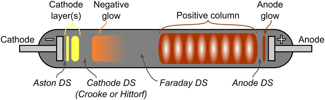
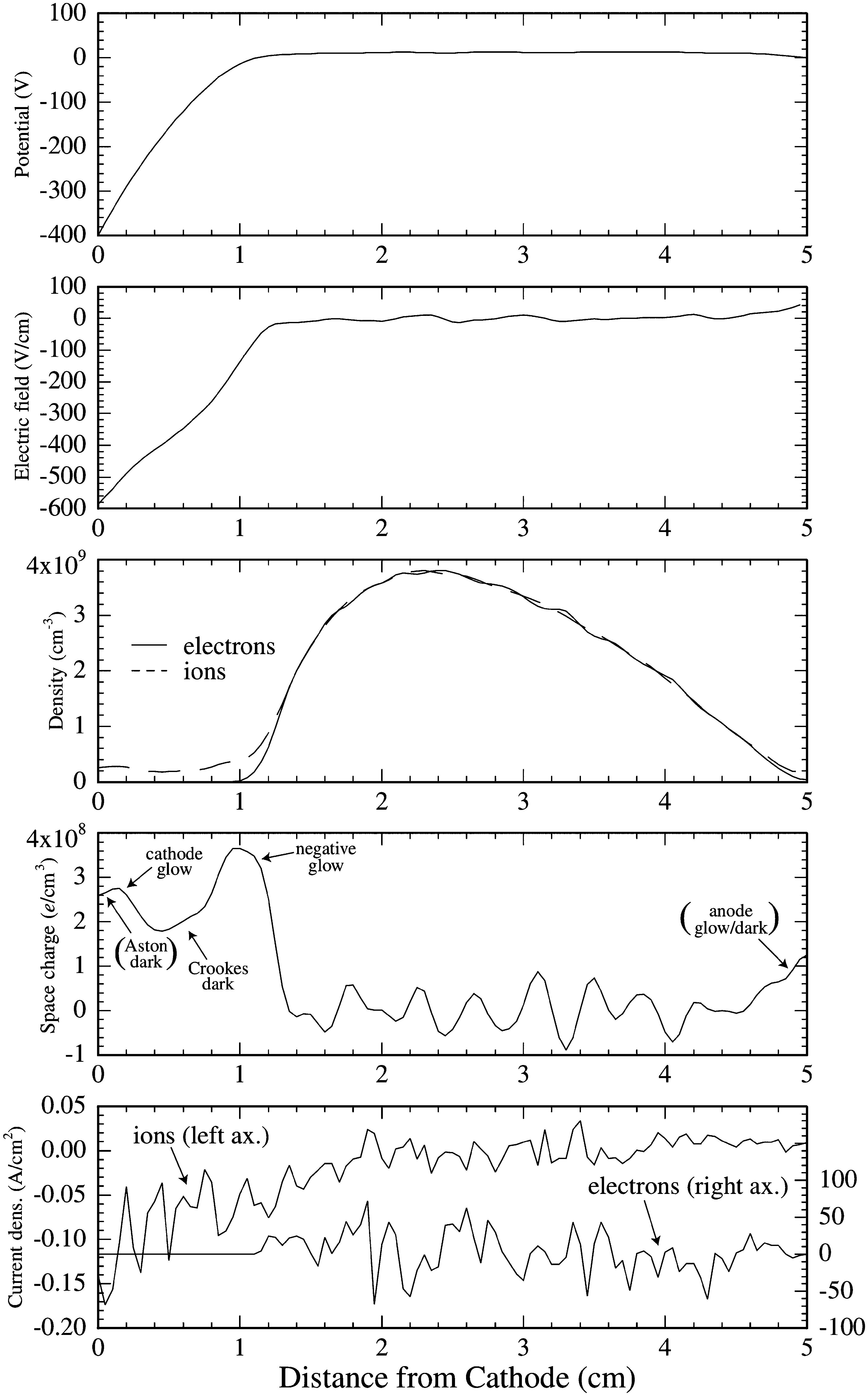
Figure1.2 Aschematicofthedcglowdischargeshowingseveraldistinctregionsthatappearbetween thecathodeandtheanode.Thecolorsofthevariousregionsassumeaneondischarge.Thedarkspacesare abbreviatedasDS.
dredsofmA(currentdensityrange10 5 –10 3 A/cm2 ),andtheworkinggaspressure istypicallyintherange0.5–300Pa.
Earlystudiesofthedcglowdischargerevealedthatitconsistsofseveraldifferentregionsbetweentheelectrodes,whichhavebeenillustratedinmoreorlessthe samewaybyseveralauthors(Francis, 1956,Ingold, 1978,Raizer, 1991,Roth, 1995, Nasser, 1971).InFig. 1.2,wepresentaschematicofthenormalglowdischargein a0.5mlongtubeusingneonat133Paastheworkinggas,whichisduetoNasser (1971).Thecathodeistypicallymadeofanelectricallyconductivemetal.Thecathode metalhasaninfluenceonthevoltagerequiredtomaintainthedischarge.Forametal thatisagoodemitterofelectrons(seediscussioninSection 1.1.4)lowervoltagesare sufficient.Immediatelynexttothecathodeisathindarklayer,theAstondarkspace. TheAstondarkspaceisfollowedbythecathodeglow,whichhasarelativelyhigh iondensity.Thesecondaryelectronsreleasedfromthecathodesurfaceareaccelerated awayfromthecathode.Thesehigh-energyelectronsundergocollisionswithneutral workinggasatomsatadistanceawayfromthecathodecorrespondingtotheionizationmeanfreepath.Inthisregionthesecondaryelectronsparticipateinexcitation andtherebygeneratethecathodeglow.Thecathodeglowisfollowedbythecathode (CrookesorHittorf)darkspace.TheregionsthatextendfromtheAstondarkspaceto thecathodedarkspacetogetherconstitutethecathodesheath.Heretheelectricfield isdirectedtowardthecathode,andthespacechargeispositiveandofrelativelyhigh density.Thecathodedarkspaceisfollowedbythenegativeglow(infact,aregionwith positivepotential),whichexhibitsasignificantlightintensity.Mostoftheionization occurshere.Theboundarytowardthecathodedarkspaceisratherabruptwhileitis diffuseontheanodesidetowardtheFaradaydarkspace.TheelectricfieldandtheenergyoftheelectronsarelowintheFaradaydarkspace.Theelectronenergyavailable forexcitationandionizationishereexhausted.Beforeenteringthisdarkregion,the potentialgradientisslightlynegativeasthespacechargereverses.Herethedensityof electronshasbecomehighenoughtocarrytheentiredischargecurrentandtomake thespacechargenegative.Theelectrondensityfallswithinthisdarkspaceregiondue torecombinationanddiffusionuntilthenetspacechargeiszeroandtheelectricfield approachesasmallconstantvalueandthepositivecolumnbegins.Thepositivecolumnisaquasineutralplasmawheretheelectricfieldisverylow.Thepositivecolumn issimplyalonguniformglow,exceptwhenstriationsareformed.Thepositivecolumn actsasaconductingpathbetweenthenegativeglowregionandtheanode.Theanode
Table1.1 Thecolorofselectedluminouszonesinthedcglowdischarge.
Gas Cathodelayers
He red pink red/pink
Ne yellow orange red/brown
Ar pink darkblue darkred
H2 red/brown paleblue pink
N2 pink blue red/yellow
Air pink blue red/yellow
BasedonFrancis(1956).
glowisabrightregionthatappearsattheendofthepositivecolumn.Oftenathindark spaceisobservedattheendofthepositivecolumn(theanodedarkspace),andaglow closetothesurfaceoftheanode(theanodeglow).
Thesize,intensity,andcolorofalltheregionsdescribedabovedependonthenatureoftheworkinggas,gaspressure,andappliedvoltage.Also,someofthefeatures maybeabsentoverparticularparameterranges.Thevariousgasesgiveadischargeof acharacteristiccolor.Thecolorsofthelightemittedfromthevariouszonesofthedc glowdischargearelistedinTable 1.1.Ifthepressureisreduced,thenthecathodedark spaceexpandsattheexpenseofthepositivecolumn.Thisisduethefactthatnowthe electronshavetotravelfarther(meanfreepathislonger)toproduceefficientionization.Forasecondaryelectronemissionyieldintherange0.05–0.1,eachsecondary electronmustinitiateanavalanchethatproducesroughly10–20ionstomaintain thedischarge.Anelectronavalancheispossiblewithinthecathodesheathofglow discharges,becausetheelectronmeanfreepathforionizingcollisionsisheresmaller thanthesheaththickness.AswewillseeinSection 7.2.3,ionizationavalancheswithin thesheathregionarenotpossibleinHiPIMSdischargesduetolowerpressuresand thinnercathodesheaths.Howmanyionseachsecondaryelectronactuallyproduces dependsontheionizationmeanfreepathandthedistancebetweentheanodeand cathode.ThisrelationisqualitativelythestatementofPaschen’slaw,whichrelates thebreakdownvoltage VB totheproductofgaspressureandelectrodeseparationand willbediscussedinSection 1.1.2.Thisalsoshowsthattheionizationprocessesinthe cathodedarkspaceareessentialforthemaintenanceofthedischarge.
Thepotentialdifferenceappliedbetweenthetwoelectrodesisgenerallynotequally distributedbetweencathodeandanode.Thespatialvariationsofthepotential,the electricfield,particledensities,spacecharge,andcurrentdensitiesalongtheaxisofa dcglowdischargeareshowninFig. 1.3.Thespatialvariationoftheplasmaparameters shownherewasfoundbyparticle-in-cellsimulationofanargondcdischargeat50Pa whenavoltageof400Visappliedacrossthe5cmdischargegap(Budtz-Jørgensen, 2001).Asthepotentialprofileindicates(Fig. 1.3A),theelectricfieldislargeinthe vicinityoftheelectrodesandalmostzerowithinthepositivecolumn.Thusalmostall theappliedvoltagedropscompletelywithinthefirstfewmillimetersinfrontofthe cathode.Thisregionadjacenttothecathode,whichisthuscharacterizedbyastrong electricfield,isthecathodefall,oroftenreferredtoasthecathodesheath.Weseein
Figure1.3 Spatialprofilesof(A)theplasmapotential,(B)theelectricfield,(C)ionandelectrondensity, (D)space-chargedensity,and(E)ionandelectroncurrentdensity.Fromparticle-in-cellsimulationofan argondcdischargeat50Pa,electrodeseparationof5cm,and 400Vappliedtothecathode.Reprinted fromBudtz-Jørgensen(2001).©Budtz-Jørgensen.Reproducedwithpermission.Allrightsreserved.
Fig. 1.3Cthatthesheathregionisdepletedofelectrons,andinFig. 1.3D,weseethat thenetspacechargeispositiveinthesheathregioninlinewithourpreviousdiscussion ofthedarkspace.ThespacechargeshowninFig. 1.3Disfoundbysubtractionofthe electrondensityfromtheiondensity.Intheplasmabulk,theplasmaisquasineutral, andtheelectronandiondensitiesarethesame.Thisspacechargedensityleadstothe electricfielddistributionseeninFig. 1.3B.
1.1.2Electricalbreakdown Electricalbreakdownisanimportantphenomenonindischargephysics.Herewederivethebreakdownvoltageasafunctionoftheproduct pL,where p istheworking gaspressure,and L isthedistancebetweentheelectrodes,whichiscommonlyreferredtoasthePaschencurve.Asimilardiscussioncanbefoundinvarioustextbooks suchasbyLiebermanandLichtenberg(2005,Section14.3),Raizer(1991,Chapter7), andRoth(1995,Section8.6).
Theelectrondensityandfluxgrowexponentiallyaswemoveaxiallyawayfrom thecathode.Thustheincreaseintheelectronfluxisproportionaltotheflux,or
where e istheelectronflux,and α isknownasTownsend’sfirstionizationcoefficient andistheinverseofthemeanfreepathforionization,thatis, α(z) ≡ 1/λiz .The electronfluxinthedirectionalongthedischargeaxis(orthedirectionoftheelectric field)is
Duetothecontinuityofthetotalcharge(creationofequalnumbersofelectron–ion pairs),wecanwrite
where e (L) fromEq.(1.2)hasbeeninserted.Sincethedischargemustbeselfsustaining,wehave e (0) = γsee i (0) and i (L) = 0.Then
istheconditionforself-sustainability.Inavacuumregion,theelectricfield E isa constant,anditfollowsthattheelectrondriftvelocity μe E isalsoaconstant.Hence theelectronenergy Ee isaconstant,allowingustotreat α asaconstantinEq.(1.4). Inthatcase,takingthelogarithmofbothsidesofEq.(1.4)gives
whichisthebreakdownconditionforadcdischarge.Theionizationcoefficientis usuallyexpressedintheform
Table1.2 ConstantsfortheTownsendionizationcoefficient.
FromLiebermanandLichtenberg(2005).
where A and B aredeterminedexperimentallyandfoundtoberoughlyconstantovera rangeofpressuresandfieldsforagivengastype.Thecoefficients A and B forvarious commongasesarelistedinTable 1.2.
Iftheminimumvoltageatwhichthedischargeinitiates,thebreakdownvoltage,is writtenas VB = EL,then
whichsolvedfor VB gives
whichisafunctionoftheproduct pL.Theproductofpressureanddistancebetween theelectrodes(pL)isasuitableparametertocharacterizethedischarge.Thecurve thatshows VB asafunctionoftheproduct pL iscalledthePaschencurve.Thusfora fixeddischargelength L,thereisanoptimumgaspressureforplasmabreakdown.By differentiatingtheexpressionforthebreakdownvoltage,Eq.(1.8),withrespectto pL andsettingthederivativeequaltozero,wecanfindthevalueof pL thatcorresponds totheminimumbreakdownvoltage(Raizer, 1991,Chapter7)
andtheminimumvoltageis
whichisreferredtoastheminimumsparkingpotential,andistheminimumvoltage atwhichelectricalbreakdowncanoccurinagivengas.
AccordingtoEq.(1.8),thebreakdownvoltageishighforlowandhighpressure andaminimumat pL givenbyEq.(1.9).Atthelowerpressurestheionizationprocess isineffectiveduetothelowelectron-neutralcollisionprobability,whereasathigher pressureselasticcollisionspreventtheelectronsfromreachinghighenoughenergy forionizationtooccur.Thenumberofgasatomsormoleculesinthespacebetween
theelectrodesisproportionalto pL.Atlowerpressure,thedistancebetweencathode andanodehastobelongertocreateadischargewithpropertiescomparabletothose ofhighpressurewithsmalldistancebetweentheelectrodes.Forlowpressure,the electronmeanfreepathislarge,andmostelectronsreachtheanodewithoutcolliding withgasatomsormolecules.Thus,atlowpressure,ahighervalueof VB isrequired togenerateenoughelectronstocausethebreakdownofthegas.Athigherpressures, theelectronmeanfreepathisshort.Theelectronsdonotgainenoughenergyfromthe electricfieldtoionizethegasatomsormoleculesduetotheirfrequentcollisionswith thegasmolecules.Therefore VB increasesasthepressureincreases.
1.1.3Thecathodesheath Allplasmasareseparatedfromthesurroundingwallsbyasheath.Wehaveseenin Section 1.1.1,andinparticularinFig. 1.3A,thatmostofthepotentialdropovera dcglowdischargeappearsacrossthecathodesheath.Therelationbetweenthesheath thickness dc ,thedischargecurrentdensity J ,andthevoltagedropacrossthecathode sheath Vc wasderivedbyChild(1911),assumingthattheinitialionenergyisnegligiblecomparedtothesheathpotential(seealsoLiebermanandLichtenberg(2005, Section6.2)),giving
where Mi istheionmass.Eq.(1.11)isreferredtoastheChildlaworthecollisionlessChild–Langmuirlaw.TheChildlawisvalidwhenthesheathpotentialislarge comparedtotheaverageenergyoftheelectrons.Asimilarrelationwasderivedby Langmuir(1913)forelectronsemittedfromahotcathodeapproachingacoldanode (nothermionicemission).Inthecollisionalregime,wherethepressureishighenough thatthechargedspeciesinteractfrequentlywithneutralgasspecies,wecanassume thattheion-neutralmeanfreepath λi isindependentoftheionvelocity(Lieberman andLichtenberg, 2005,Section6.6).ThisgivesthecollisionalChildlaw
Alternatively,assumingthatthediffusionofionsisnegligible,comparedtothedrift duetoanelectricfield,andassumingthattheionmobility μi isindependentoftheion velocity,weget
whichisreferredtoastheMott–Gurneylaw.Itwasderivedtodescribethecurrentat theinterfaceofasemiconductorandinsulator(MottandGurney, 1948,ChapterV)and lateradaptedtodescribethecurrentthroughthedischargesheathbyCobine(1958).
Equation(1.13)isvalidonlyatveryhighpressures(lowdriftvelocities).Therelation betweenthecurrentdensity,sheathvoltagedrop,andthesheaththicknessgivenby Eqs.(1.12)and(1.13)issometimesreferredtoasthecollisionalChild–Langmuir law.Wenoteherethatthescalingsofthecurrentdensitywithboth Vc and dc in Eq.(1.12)aredifferentfromEq.(1.13).Ithasbeendemonstratedbyexperiments thattheMott–Gurneylaw(Eq.(1.13))appliestoadcglowdischargeinhydrogen (Lisovskiyetal., 2016)andnitrogen(Lisovskiyetal., 2014)formostofthepressure rangefrom10to333Pa.
1.1.4Secondaryelectronemission Theemissionofsecondaryelectronsasaresultofionsorneutralsbombardinga metallicsurfaceplaysanimportantroleindischargephysics.Thesecondaryelectron emissionyieldorcoefficient γsee isdefinedasthenumberofsecondaryelectronsemittedperincidentspecies.Thesecondaryelectronemissionyieldgenerallydependson thematerialbeingbombarded,itssurfacecondition,thetypeofbombardingspecies, andthekineticenergyofthebombardingspecies.Thesputtertargetsareheldathigh negativepotentials,andthusthesecondaryelectronsareacceleratedawayfromthe targetsurfacewithinitialenergyequaltothetargetpotential.Inmanycases,these electronssustainthedischargebyionizationoftheneutralworkinggas.Theseions thenbombardthecathodetargetandsubsequentlyreleasemoresecondaryelectrons.
Asafirstapproximation,thesecondaryelectronemissionyieldisindependentof thevelocityofthebombardingparticlewhiletheirenergyislow,sincetheelectron emissionoccursduetotransferofthepotentialenergyoftheincomingionoratom toanelectroninthetarget(Hagstrum, 1954,Abroyanetal., 1967).ThisconstantsecondaryelectronemissionyieldisattributedtoanAugerprocessandisreferredtoas potentialemission.Theenergy-dependentportionofthesecondaryelectronemission yieldiscalledkineticemission.Kineticemissionoccurswhenabombardingparticle transferssufficientkineticenergytoanelectroninthetarget.Typically,itstartscontributingtothetotalsecondaryelectronemissionyieldatathresholdenergyofaround afewhundredelectronvolts.Thisprocessdominatesathigherenergies.Bothexperimentaldataandtheorypredictalineardependenceofthesecondaryelectronemission yieldonthebombardingparticleenergyclosetothethresholdenergy,andlineardependenceonthebombardingvelocityathigherenergies(Abroyanetal., 1967,Parilis andKishinevskii, 1960,Cawthron, 1971,Baragiolaetal., 1979,Hasselkamp, 1992). Atmuchhigherenergies,experimentaldatashowthattheelectronyieldstartsdecreasingwithincreasingbombardingvelocity.Thisoccursforabombardingenergy ofaround100keVforH+ (Hasselkamp, 1992).Thetwodifferentmechanismsare consideredtobedetachable,sothetotalelectronemissionyieldiswrittenas
where γp and γk arethecontributionsfrompotentialandkineticemissiontothetotal yield,respectively.Inadditiontotheenergyoftheimpactingparticle,thesecondary