https://ebookmass.com/product/ground-improvement-with-
Instant digital products (PDF, ePub, MOBI) ready for you
Download now and discover formats that fit your needs...
Process Improvement with Electronic Health Records 1st Edition
https://ebookmass.com/product/process-improvement-with-electronichealth-records-1st-edition/
ebookmass.com
Molecular Nutrition: Carbohydrates Vinood B. Patel
https://ebookmass.com/product/molecular-nutrition-carbohydratesvinood-b-patel/
ebookmass.com
Geotechnical Engineers Portable Handbook, Second Edition 2nd
https://ebookmass.com/product/geotechnical-engineers-portablehandbook-second-edition-2nd/
ebookmass.com
Beyond the ancient quarrel: literature, philosophy, and J.M. Coetzee First Edition Coetzee
https://ebookmass.com/product/beyond-the-ancient-quarrel-literaturephilosophy-and-j-m-coetzee-first-edition-coetzee/ ebookmass.com
A Cowboy's Forever Faithful (Sweet View Ranch Western Cowboy Romance book 1) (Sweet View Ranch Western Christian Cowboy Romance) Jessie Gussman
https://ebookmass.com/product/a-cowboys-forever-faithful-sweet-viewranch-western-cowboy-romance-book-1-sweet-view-ranch-westernchristian-cowboy-romance-jessie-gussman/
ebookmass.com
Electronic Principles 9th Edition Albert P. Malvino
https://ebookmass.com/product/electronic-principles-9th-editionalbert-p-malvino/
ebookmass.com
Gerente profesional de proyectos 1st Edition Juan Francisco Esquembre
https://ebookmass.com/product/gerente-profesional-de-proyectos-1stedition-juan-francisco-esquembre/
ebookmass.com
Core Radiology: A Visual Approach to Diagnostic Imaging
https://ebookmass.com/product/core-radiology-a-visual-approach-todiagnostic-imaging/
ebookmass.com
Critical Criminological Perspectives Jodie Hodgson Gender Power And Restorative Justice A Feminist Critique Palgrave Macmillan 2022 Desconocido
https://ebookmass.com/product/critical-criminological-perspectivesjodie-hodgson-gender-power-and-restorative-justice-a-feministcritique-palgrave-macmillan-2022-desconocido/
ebookmass.com
https://ebookmass.com/product/etextbook-978-1305089723-ethics-incounseling-psychotherapy/
ebookmass.com
GeotechnicalInvestigations andImprovementofGround Conditions Geotechnical Investigationsand Improvementof GroundConditions An imprint of Elsevier
AnjanPatel
WoodheadPublishingisanimprintofElsevier
TheOfficers’MessBusinessCentre,RoystonRoad,Duxford,CB224QH,UnitedKingdom 50HampshireStreet,5thFloor,Cambridge,MA02139,UnitedStates TheBoulevard,LangfordLane,Kidlington,OX51GB,UnitedKingdom
© 2019ElsevierInc.Allrightsreserved.
Nopartofthispublicationmaybereproducedortransmittedinanyformorbyanymeans, electronicormechanical,includingphotocopying,recording,oranyinformationstorageand retrievalsystem,withoutpermissioninwritingfromthepublisher.Detailsonhowtoseek permission,furtherinformationaboutthePublisher’spermissionspoliciesandour arrangementswithorganizationssuchastheCopyrightClearanceCenterandtheCopyright LicensingAgency,canbefoundatourwebsite: www.elsevier.com/permissions
Thisbookandtheindividualcontributionscontainedinitareprotectedundercopyrightbythe Publisher(otherthanasmaybenotedherein).
Notices
Knowledgeandbestpracticeinthisfieldareconstantlychanging.Asnewresearchand experiencebroadenourunderstanding,changesinresearchmethods,professionalpractices,or medicaltreatmentmaybecomenecessary.
Practitionersandresearchersmustalwaysrelyontheirownexperienceandknowledgein evaluatingandusinganyinformation,methods,compounds,orexperimentsdescribedherein. Inusingsuchinformationormethodstheyshouldbemindfuloftheirownsafetyandthesafety ofothers,includingpartiesforwhomtheyhaveaprofessionalresponsibility.
Tothefullestextentofthelaw,neitherthePublishernortheauthors,contributors,oreditors, assumeanyliabilityforanyinjuryand/ordamagetopersonsorpropertyasamatterofproducts liability,negligenceorotherwise,orfromanyuseoroperationofanymethods,products, instructions,orideascontainedinthematerialherein.
LibraryofCongressCataloging-in-PublicationData
AcatalogrecordforthisbookisavailablefromtheLibraryofCongress
BritishLibraryCataloguing-in-PublicationData
AcataloguerecordforthisbookisavailablefromtheBritishLibrary
ISBN:978-0-12-817048-9(print)
ISBN:978-0-12-817049-6(online)
ForinformationonallWoodheadpublicationsvisitour websiteat https://www.elsevier.com/books-and-journals
Publisher: MatthewDeans
AcquisitionEditor: GlynJones
EditorialProjectManager: AnaClaudiaGarcia
ProductionProjectManager: DebasishGhosh
CoverDesigner: VictoriaPearsonEsser
Introduction 1.1Introduction Groundimprovementisrequired,whereverproblematicsoils/rocksareencountered. Thebasicpurposeistomakethesubsurfaceconditionssuitableforconstructionpurposes.Therearevariousmethodsofgroundimprovementavailableandtheselection ofatechniqueoracombinationoftechniquesdependsuponseveralfactors.Thedifferentpurposesofgroundimprovementandabriefdescriptionofthedifferent methodsandtheirselectioncriteriaispresentedinthischapter.
1.1.1Purposeofgroundimprovement Ground-improvementmethodsarethosethatarecapableofimprovingcertaincharacteristics(e.g.increaseinbearingcapacity,reductionintotalaswellasdifferential settlement,reductioninpermeability,slopestability,preventionofsoilerosioncaused bypipingandseepage,reductionofupliftpressure,decreaseinliquefactionpotential ofsoil,reductionofswellingandcrackingofsoils,identificationofsuitabilityofsite tofacilitateconstructionworks,etc.)ofpoorgroundforcivilengineeringconstructionsandvariousinfrastructuredevelopments.Soagroundimprovementmethod ortechniqueisrequiredtoalterthestate,nature,ormassbehaviourofgroundmaterialsinacontrolledmannerinordertoachieveanexpectedandsatisfactoryresponse toexistingorprojectedenvironmentalandengineeringactions. Therearealternateoptionstogroundimprovementaswell.Theseare
a. toremoveandreplacethesoilmasswithanothertypeofsoilsorothergeomaterialsofa suitablequalityfortheconstructionwork
b. tobypassthepoorsoilwiththehelpofasuitabletechniquelikepilefoundation
c. toalterthedesign(heightandconfiguration)ofstructurestoovercometheground limitations
d. tochangetheconstructionsiteandlookforanewone.
However,duetothescarcityoflandinpresentconditions,heavyloadingstructures, competitivedesign,theneedforspeedyconstruction,andvariouspoliticalandeconomicissues,aground-improvementtechniquemaybetheonlyfeasibleoptionfor civilengineeringconstructions.Thissituationisoutlinedin Fig.1.1,whichdemonstratesthatwhenthegroundisproblematicinmostofthecasesweneedtoimprove thesoilmassbyselectingaproperground-improvementtechnique(s).Theselectionof ground-improvementtechniquesdependsuponvariousfactorslikethecostandtime
2 GeotechnicalInvestigationsandImprovementofGroundConditions
Problematic cases
Collapsible soil
Liquefiable soil
Filling materials
Loose deposits
Swelling soil
Soft and marshy ground
Karst topography
Nonuniform soil/rock strata
Potential for slope instability
Excessive seepage
High lift pressure
Erosion, piping
Options available
1. Remove and replace
2. Bypass
3. Change site location
4. Design alteration
5. Improve in situ soil properties (ground improvement)
Technical, practical, political and economical issues
Constraints Selection criteria
Cost, time, purpose, volume of treatment area, soil properties, accessibility, availability of materials, equipment and manpower, environmental factor, local experience and preference
Fig.1.1 Necessityandselectionofground-improvementtechniquesforconstructionprojects.
availabletocompletetheproject,reasonsforimprovingtheground,extentanddepth ofgroundtobetreated,geotechnicalpropertiesoftheexistinginsitusoils/rocks, accessibilitytotheprojectsite,availabilityofmaterials,equipmentsandmanpower requiredtoimprovetheground,environmentalfactors,localexperience,andpreferenceofcontractorsandengineers.
1.1.2Preliminaryevaluationforgroundimprovement Asmentionedpreviously,therequirementforandselectionofvariousgroundimprovementtechniquesarepurelysiteandprojectspecific.Itisessentialthatthesite characterizationiscompletedbeforeimplementationoftheground-improvementprocess.First,itneedstobedecidedwhethergroundimprovementisrequiredforthespecificprojectattheparticularsiteornot?Inordertodecidethisweneedtoanalyzethe variousparametersrelatedtothegroundthataffectthestabilityandserviceabilityof thestructures.Asimpleexampleofapreliminaryevaluationforgroundimprovement toconstructabuildinghasbeenpresentedasaflowchartin Fig.1.2.Similarmatrices canbeformedfordifferentstructurestobeconstructedindifferentsitestoevaluatethe necessityofgroundimprovement.
1.1.3Methodsofgroundimprovement Aclassificationofvariousground-improvementtechniquescanbedonebasedupon theirbasicprinciplesandthisispresentedin Table1.1. Allofthetechniquesmentionedin Table1.1 haveoneormorethanoneofthefollowingmainfunctions:
a. Toincreasethebearingcapacity
b. Tocontroldeformationsandaccelerateconsolidation
c. Toprovidelateralstability
Fig.1.2 Necessityofground-improvement:preliminaryevaluation.
d. Toformseepagecut-offandenvironmentalcontrol
e. Toincreaseliquefactionresistance
f. Tofacilitatetheworkingsiteconditions.
Dependinguponthespecificprojectrequirements,itisnecessarytoselectone,or morethanone,oftheground-improvementtechniquesforaparticularsitebyconsideringotherfactorsliketimeandcost,volumeanddepthofwork,etc.,asmentionedin theprevioussection.Someofthecommonmethodsalongwiththeirbasicpurposes aresummarizedin Table1.2.
Itisworthmentioningthataparticularground-improvementtechniquecanbeused onlyforaparticulartypeoragroupofsoils,asshownin Fig.1.3.
4 GeotechnicalInvestigationsandImprovementofGroundConditions
Table1.1 Classificationofground-improvementtechniquesbasedupontheirbasic principles
BasicprinciplesSomeofthemethods
ConsolidationWickdrainsorprefabricatedverticaldrains(PVD), vacuumconsolidation,preloading,surchargefill, electro-osmosis
DensificationVibro-compaction,vibro-flotation,dynamiccompaction, blasting
ReinforcementApplicationofgeosyntheticmaterialsandnaturalfibres, retainingwalls,soilnailing,soilanchoring,micropiles, stonecolumns
Chemicalstabilizationby deepmixingmethods
Chemicalstabilizationby grouting
Chemicallimeandcementpiles
Permeationgroutingwithparticulateorchemicalgrouts, compactiongrouting,jetgrouting,hydro-fracture grouting,etc.
ThermalstabilizationGroundfreezing,vitrification
Electro-treatmentElectro-kineticremediation,electro-heating, electro-kineticfencing,bioelectro-kineticinjection LoadreductionUseofEPS(expandedpolystyrene)geofoams,crumb rubbertire,sawedlumberwaste,foamglassaggregates, clamshells,LECA(lightweightexpandedclay aggregate),expandedshellclayandslates,cellular concrete,pumiceandindustrialwasteslikeslag,etc.
Similarly,themaximumeffectivedepthandtheeconomicalsizeofthetreatment areavariesfrommethodtomethod,assummarizedin Table1.3
1.1.4Scope l Developingnewmachinerytoexecutetheworkinlesstime,particularlyfordeep compaction
l Automationofequipmentforinsitumonitoringandqualitycheck
l Developmentofproperguidelinessoastoenhancetheeffectivenessofdifferentgroundimprovementtechniques.Also,theregularrevisionoftheexistingguidelinesisrequired, baseduponnewsitecondition,climaticconditions,andnewchallenges
l Innovatingnewconstructionmaterials,particularlyfromdifferentwastes
l Developmentofnewcost-effectivetechniquestoreplacetheexpensiveones,likefreezing, electro-osmosis,vacuumconsolidation,etc.Interdisciplinaryworktoexplorenewmethods likenanotechnologyandmicrobialgeotechniques,biorockformations,inventionofcatalyst andenzymesthatcanconvertsoilintorocklikematerials,etc.
l Tomakethesetechnologiesmoreenvironmentallyfriendly
l Analysisoftheeffectofclimatechangeonperformanceofdifferentsoilstabilizers,etc.
Table1.2 Purposesofsomeofthecommonmethodsforgroundimprovement
Methods
Vibrocompaction, blasting, preloading
Dynamic compaction
Soilnailing
Mechanical stabilization, micropiles,fibrereinforcement
Vacuum consolidation, electro-osmosis
Lightweightfill
Stonecolumns
Permeation grouting
Electro-heating
Jetgrouting,deep soilmixing,lime column
Groundfreezing
Vitrification
Gravel Sand
Vibro-compaction
Vibro-displacement compaction
Particulate grout
Chemical grout
Displacement grout
Preloading
Dynamic compaction
Electro-osmosis
Reinforcement
Thermal treatment
Remove and replace
Prewetting
Fig.1.3 Variousground-improvementmethodsaspertheirapplicabilitytodifferentsoilmass. BasedonMitchell,J.K.,1981.Soilimprovement:stateoftheartreport.In:Proceedingsof10th InternationalConferenceonSoilMechanicsandFoundationEngineering,Stockholm,4, pp.509–565.
Table1.3 Maximumeffectivedepthandeconomicalsizeoftreatmentareaforsomeofthe ground-treatmentmethods
Method
Maximumeffective depth/economicalsizeof treatmentareaMethod
BlastingAbout20–25mbutnot neartogroundsurface/ smallarea
Maximumeffectivedepth andeconomicalsizeof treatmentarea
PreloadingEconomicalforsmallarea
Vibratory roller 3m/anysizeDynamic compaction 30m/largearea
GroutingUnlimited/smallareaVibroflotation 30m/largearea
Electroosmosis 20m/smallareaStone columns 20m/mediumtolargearea
Heating/ freezing 15m/smallareaChemical limepiles 45m/mediumtolargearea
Soilcompaction 2.1Introduction Compactionistheprocessofapplyingmechanicalenergytoasoilmasssoasto rearrangetheparticlesandmakingitdensethroughtheexpulsionofairfromthevoids betweenthesoilgrains.Themainobjectivesofsoilcompactionaretoimprovethe engineeringpropertiesofanexistingsoilortofacilitatetheworkduringplacingof fills.Theobjectivesare
l toincreasetheshearstrengthandthereforebearingcapacityofsoil
l toincreasethestiffnessandthereforereducesettlement
l todecreasethevoidratiothusmakingthesoillesspermeable
l toincreasetheerosionresistanceofgeomaterials
l toimproveliquefactionresistanceofsoilbypreventingthebuildupoflargewaterpressures duringearthquakes.
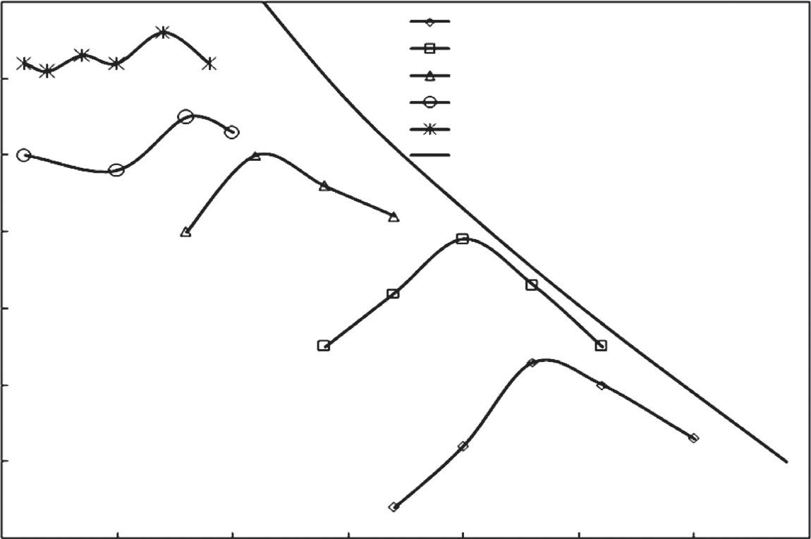
2.2Compactiontheory Inordertoexplainthetheoriesofsoilcompaction,itisnecessarytofirstunderstand therelationshipsbetweenthedrydensityandthemoisturecontent(knownascompactioncurves)asobtainedduringcompactioninthelaboratoryorinthesite.Thetypical curvesobtainedfromdifferenttypesofsoilhavebeendepictedin Fig.2.1.Withan increaseinwatercontent,thedrydensitykeepsonincreasinguptoacertainpoint (correspondingtotheoptimummoisturecontent(OMC)andthemaximumdrydensity(MDD))andthenitstartsdecreasing.Thezeroairvoidline,alsoknownasthe 100%saturationlineasshownin Fig.2.1,isalimitinglinecorrespondingtonoair inthesoil,i.e.allthevoidsarefilledwithwater.Itcanbeaddedherethatgranular soiltypicallyhavefairlysteepcompactioncurvesexhibitinglargechangesindensity withsmallchangesinmoisturecontent.Ontheotherhand,highlyplasticclaysexhibit fairlyflatcompactioncurves.TheMDDishigherforcoarsersoilsandcorrespondsto alowervalueofOMC.Somecohesionlesssoilscanexhibittwopeaksinthecompactioncurve(oneinverydryconditions,wheretherearenocapillarytensionstoresist thecompactioneffort,andtheotherattheOMC,whereoptimumlubricationbetween particlesoccurs).
Thecompactioninasoilmasscanbeachievedinvariousways,assummarizedin Table2.1.
Theeffectivenessofanyofthesecompactionmethodsdependsupon(1)thefrictionalforcebetweensoilparticlessupportedbythecapillaryaction,and(2)thelubricationeffectofthemoisturefilmaroundthesoilparticle,whichinturndependsupon thesize,shape,soilmineralogy,andtheporewater.AtOMC,theamountofwateris justsufficienttoneutralizethecapillaryforceandthecompactingforceisfully GeotechnicalInvestigationsandImprovementofGroundConditions. https://doi.org/10.1016/B978-0-12-817048-9.00002-0 © 2019ElsevierInc.Allrightsreserved.
2.00
High plastic clay
Low plastic clay
Clayey silty sand
Sand
Gravel
Zero air void or 100% saturation line
Fig.2.1 Typicalcompactioncurvesindifferenttypesofsoils.
Table2.1 Generalcompactionmethodsinlaboratoryandinthefield
BasicprincipleMethods/equipment
StaticloadingRubber-tyredrollers
Staticloadingandpress
ImpactloadingDynamiccompaction
Fallingweightandhammer
Rapidimpactcompactor
Pneumatic-tyredrollers(forcohesiveaswellasnoncohesivesoilin 15–30cmthicklayers) 8
Vibrating
Handandmechanicallyoperatedtampers(tocompactsoiladjacentto existingstructuresandareasthatarenotaccessibleeasilybyother ways)
Vibratinghammer
Hand-operatedvibrationplates
Motorizedvibratoryrollers
Vibratoryplatecompactor(tocompactgranularsoilstoveryhighdry density)
Rolling Smooth-wheelrollers(forfinishingoperationsaftercompactionoffill andforcompactinggranularbasecoarseforhighways)
Vibratoryrollers(forcompactinggranularsoilwithnofinesinlayers ofupto1mthickness)
High-energyimpactrollers(forcompactionatafasterrateandto greaterdepths)
Gyrating
Kneading
Kneadingand tamping
vibratingprobeorvibro-flot
Sheep-footrollers(applicabletocohesivesoilin15–30cmthick layers,usefulforwastecompactionatlandfills)
1. Hydration
2. Lubrication
3. Swelling
4. Saturation
Fig.2.2 Stagesofwetting duringcompaction. (BasedonHogentogler,C.A., 1936.EssentialsofSoil Compaction,Proceedings HighwayResearchBoard, NationalResearchCouncil, Washington,DC,309–316.)
utilizedtorearrangethesoilparticlesmakingitmoredenseincomparisonwiththe MDD.BeyondOMC,thethicknessofwaterfilmincreases;asitcannotbindthesoil particlesintoagroupthedensitythereforedecreases.Itshouldbenotedthatwhilst obtainingacompactioncurve,thesoilmasspassesthroughfourstagesofwetting,i.e. hydration,lubrication,swelling,andsaturation,asshownin Fig.2.2.
Inthestageofhydrationwaterisjustabsorbedbythesoilparticlesandsticksto theirsurface.Inthestageoflubricationpartofwateractsasalubricatingagent enablingtherearrangementofthesoilparticlesintoacloserproximitywithoutthe expulsionofalltheairfromthevoids.Inthestageofswelling,whichhappenstooccur beyondtheOMC,thesoilmassswellswiththeaircontentremainingconstant,and withtheadditionofmorewateratthesaturationstageallairisdisplacedduringcompactionandthesoilbecomessaturated.Moreover,thedecreasedeffectivenessofcompactionathighermoisturecontentsbeyondOMCisduetothetaperingofairand buildupofporewaterpressure.Theexplanationofcompactiontheoryintermsof physicochemicalandsoil-structureconsiderationstendstoshowthatinthedryofoptimumtheparticlesarerandomlyorientedrepresentingflocculatedstructure,whereas thesoilparticlesarearrangedinadispersedmannerinthewetofoptimum.
2.3Effectonsoilproperties Itcanbeseenfrom Fig.2.2 thatthesamedrydensitycanbeachievedcorrespondingto twomoisturecontents,oneatthedryofoptimumandotheratthewetofoptimum. Clayscompacteddryofoptimumhaveaflocculatedfabric,whichgenerallycorrespondstohigherpermeability,greaterstrengthandstiffness,andincreasedbrittleness. Ontheotherhand,clayscompactedwetofoptimumhaveadispersedfabric,which correspondstolowerpermeability,lowerstrengthandstiffness,butmoreductility.
Thechangeinstrength,stiffness,permeability,compressibility,andswellingof soilscorrespondingtothedryorwetofoptimumissummarizedin Table2.2.
Table2.2 Effectofcompactiononsoilproperties
SoilpropertiesEffects
Strength
l Thestrengthatdryofoptimumishigherthanwetofoptimum
l Atlargestrains,theultimatestrengthofsoilcompacteddryandwet ofoptimumarealmostequal
l Highercompactionenergiescanproduceslightlylowerstrength whenafine-grainedsoiliscompactedatawatercontenthigherthan theoptimum
l Ifmaterialcompacteddryofoptimumbecomessaturated,thereisa decreaseinstrength,whichcanbelessthanthatofthesamesoil compactedwetofoptimum
l Onwetofoptimum,soilcompactedbykneadingactionhasless shearstrengthascomparedtosoilcompactedbystaticcompaction method
Stiffness
Permeability
Compressibility
l Thestiffnessatdryofoptimumissubstantiallylargerthanwhen compactedwetofoptimum
l Ifmaterialcompacteddryofoptimumbecomessaturated,thereisa decreaseinstiffness,whichcanbelessthanthatofthesamesoil compactedwetofoptimum
l Permeabilityatconstantcompactiveeffortdecreaseswithincreasing watercontentandreachesaminimumatabouttheoptimummoisture content
l Ifthecompactioneffortisincreased,thepermeabilityofsoil decreases
l Soilsonthedrysidearelesscompressible.However,the compressibilityofsoilincreasesinthehigh-andlow-pressurerange ondryofoptimumandwetofoptimum,respectively
l Compactionbykneadingorimpactmethodcreatesamoredispersed structureandhenceariseincompressibility
Swelling/ shrinkage
l Soilscompacteddryofoptimumhavemoreswellingpotentialbut shrinklessondryingcomparedwiththosecompactedwetof optimum
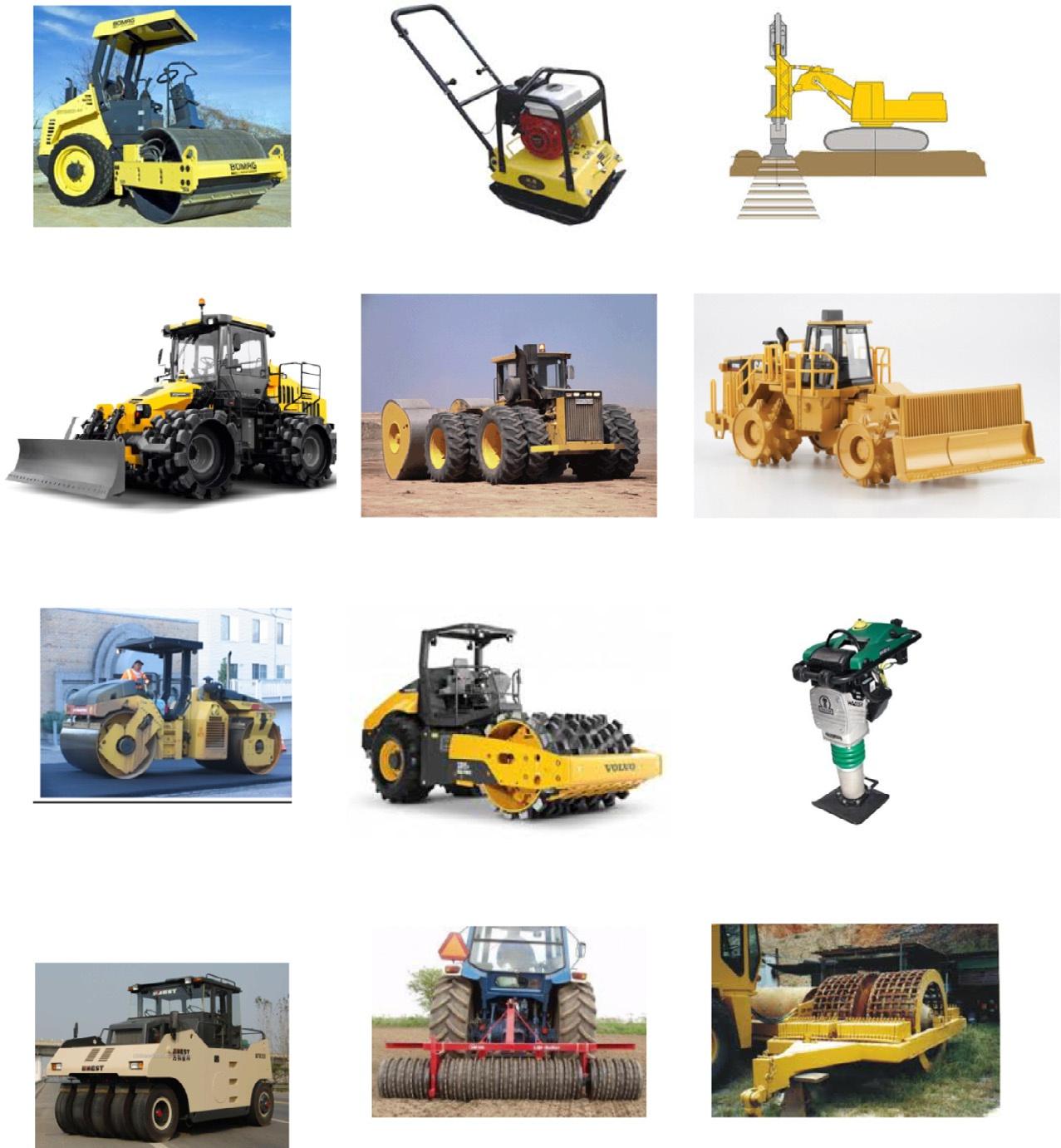
2.4Instrumentsandmethods Thevariousmethodsofsoilcompactionarealsoincludedin Table2.1.Thedifferent typesofsoilcompactinginstrumentsaredepictedin Fig.2.3. Itmustbenotedthattheeffectivedepthofcompactionvariesfrommethodto method.Forexample,smoothwheelrollercompactseffectivelyonlyto 200–300mm,whereastheimpactrollercanprovidedeeper(2–3m)compaction. So,thecompactionofthickfillsmustbedoneinaseriesoflifts.Generally,thethicknessofeachliftvariesfrom0.15to0.3mdependinguponthetypesofsoil,relative compactionthatisrequired,fieldcompactionenergy(typeofcompactionequipment
andnumberofpasses)andtheQA/QC(qualityassurance/qualitycontrol)plan.As such,byusingconventionalvibratoryrollers,High-energyimpactcompaction,rapid impactcompaction,dynamiccompaction,andvibro-flotation,soilcanbecompacted uptoaneffectivedepthof1.5,1.5–5,4–6,6–12,and10–20m,respectively.The vibro-compaction,vibro-flotation,anddynamiccompactionmethodsarediscussed inaseparatesectionlaterinthischapter.Theothermethods,whichgenerallyoperate byrollingontheearthsurface,requirethatpropermoisturecontent(correspondingto OMC)ismaintainedinthefield.Moreover,itshouldbenotedthatitisdifficultto achieveahighlevelofcompactioninthethinliftoveraweaksubgradeandthehigh stressesinthelowersoilmayproduceshearfailureandexcessiverutting.Hence,itis essentialtomonitorthecompactionofeachliftduringfillplacement.Nowadays,it hasbecomeveryeasytomonitortheinsitucompactiononareal-timebasisbyusing intelligentcompaction(IC),especiallyforroadconstruction.Theintelligent
Pneumatic tyred roller
Vibratory roller Vibrating plate compactor Rapid impact compactor
Tamping roller High energy impact roller Landfill compactor
Smooth wheel rollers Sheep-footed roller
Upright rammer
Lift roller
Grid roller
Fig.2.3 Differenttypesofsoilcompactinginstruments.
compaction(IC)instrumentisbasicallyamodernvibratoryrollerequippedwithan integratedmeasurementsystem,anonboardcomputerreportingsystem,globalpositioningsystem(GPS)basedmapping,andoptionalfeedbackcontrol.TheICroller helpsinreal-timecompactionmonitoringandtimelyadjustmentstothecompaction processbyintegratingmeasurement,documentation,andcontrolsystems.
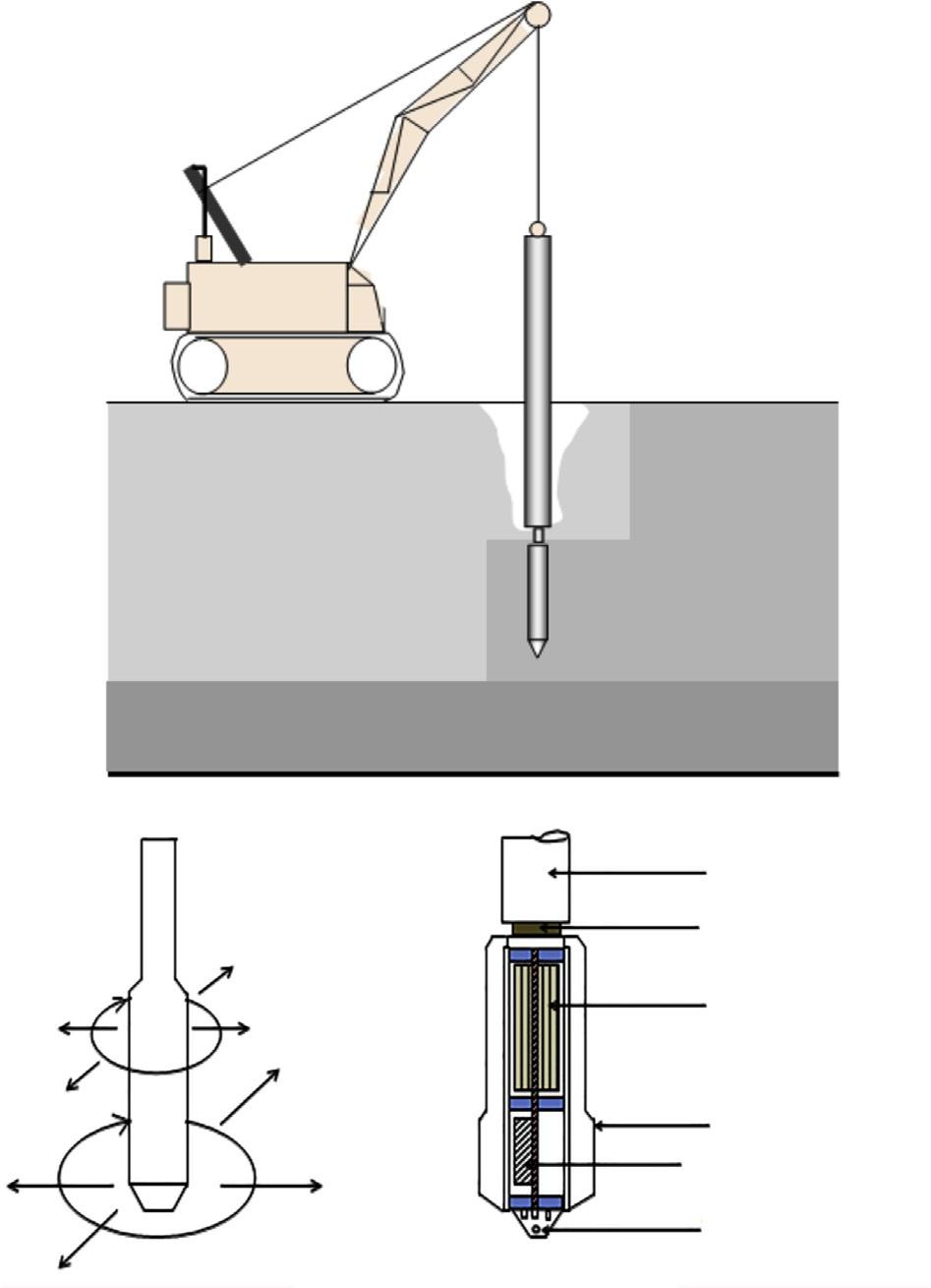
2.5Vibro-techniquesforcompaction Vibro-compactionisamethodofgroundimprovementwherethecohesionlesssoil getscompactedbymeansofadown-holevibratorknownasvibro-flot.Waterunder highpressureisjettedsidewaysanddownwardsfromthevibro-flottoassistthepenetrationprocess,asshownin Fig.2.4.
Thevibro-flotsareusually30–45cmindiameterandabout3–5mlongcontaining weightsmountedeccentricallyonacentralshaftdrivenbyelectricorhydraulicpower
Fig.2.4 Vibro-compactionmethod.
Vibro-compaction operation
Schematic view of vibrator
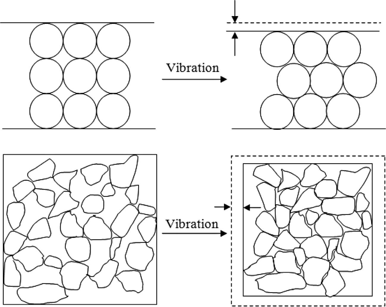
andsuspendedbyacrane.Vibrationcausesrearrangementofthesoilparticlesand duringtheprocesssmallersizedparticlesfillthevoidsbetweenthelargersizeparticlesandthusminimizethevoidratio.Thisisillustratedin Fig.2.5.
Thebenefitsofusingthevibro-compactionmethodforgroundimprovementas comparedtoothermethodsarethat(1)as pecificdegreeofgroundimprovementcan beachievedasrequiredbytheproject,(2)itistimeandcosteffective,and(3)itcan eliminatethenecessityofexcavationa ndreplacementonsite.Withthehelpof vibro-compaction,thebearingcapacityofnoncohesivesoilscanbeincreasedand thesettlementcanbereducedunderstructuralloads.Also,ithelpsinmitigatingliquefactionanddifferentialsettlement.Vibro-compactioncanbeimplementedfor variousapplicationslikebuildings,embankments,bridgeabutments,retaining walls,etc.However,theeffectivenessof thevibro-compactiontechniquedepends upontheinsitusoilcharacteristicsand mostlyonfinecontentbeingpresentin thenoncohesivesoils.Inordertogetgood resultswithvibro-compactionthesilt andclaycontentinthesoilshouldnotbe >10%– 15%and3%,respectively.Moreover,atshallowdepth(upto2mfromthe groundsurface)thevibro-compaction methodmaynotbeeffectivebecauseofthelackofverticalconfinement.Therelativeeffectivenessofvibro-compactionunderdifferentgroundconditionsispresentedin Table2.3
Fig.2.5 Particlerearrangementduringsoilcompaction.
Table2.3 Effectivenessofvibro-compactionindifferenttypesofsoils
GroundtypeRelativeeffectiveness
SandsExcellent
SiltysandsMarginaltogood SiltsPoor
ClaysNotapplicable
MinesoilsGood(ifcleangranular)
DumpedfillDependentonnatureoffill
GarbageNotapplicable
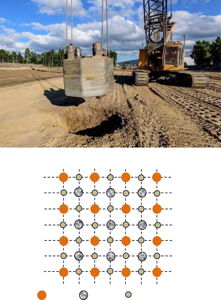
2.6Dynamiccompaction Indynamiccompaction,alargeweightusuallyof100–400kNisdroppedrepeatedly fromaheightofabout5–30montothegroundusingapredeterminedgridpattern,as depictedin Fig.2.6,inordertodensifythesoilmassortoimproveitscompactness.
Themaximumeffectivedepthofcompactionusingdynamiccompactioncanbe determinedbyusingtheformulaasfollows:
where W isthedroppedweightintonnes, H istheheightofdropinmetresandthe value n isafactorthatdependsuponthetypeofsoil.Thisdepthisalsoinfluenced byotherfactorssuchasthestratigraphyofthesoil,thedegreeofsaturation,the wayinwhichtheweightisdropped,andthepresenceofanydampingsoillayers. Thevalueof n generallyvariesfrom0.4to0.8.Thenumberofdropsateachgridpoint locationcanbecalculatedusingEq. (2.2) asfollows:
where E istheappliedenergy, N isnumberofdropsateachgridpointlocation, W is droppedweight, H istheheightofdrop, P isnumberofpasses,and S isthegridspacing.Thedroppointspacingisgenerallyselectedas1%to2%timesthediameteror widthofthedroppedblock.
Thedynamiccompactionmethodcanbeusedforvariousapplicationssuchasfor thetreatmentofindustrialwarehouses,portandairportplatforms,roadsandrailways embankments,heavystoragetanks,nonorganicheterogeneousfillorman-madegroundcontaininglargesblocksasobstructions,andsoilsthataresusceptibletoliquefaction.Themajoradvantageofadoptingthedynamiccompactionmethodisitsveryhigh productionrate(itcanbeusedtotreatanareaof >104 m2/month).Moreover,this methodiseffectivebothinsaturatedandnonsaturatedsoils.Insoftground,the methodofdynamiccompactionhasbeenprovedasabetteralternativetopreloading, foundationpiling,orsoilundercuttingandreplacement.
E ¼ N W H P ðÞ=S2
Fig.2.6 Dynamiccompaction. (A)Droppingofweightfromacertain weight(Menard),(B)Droplocations.
However,thedisadvantageordifficultyinadoptingthedynamiccompaction methodisthatitrequiresanintensiveinsitutestingprogramme(standardpenetration test,conepenetrationtest,pressuremetertestorloadsettlementtest,etc.)toverify thatthedesiredimprovementhasbeenachievedinthefield.Moreover,constantmonitoringisrequiredtocheckfortheformationofcrater,groundheave,groundvibration, inducedsettlement,andporepressuredevelopmentduringtheoperationofthis methodonthesite.Thismethodbecomesmorecomplicatedinsiltyandclayey depositsbelowthegroundwaterduetoitsrelativelylowpermeability.Insuchcases, iftheenergylevelisveryhigh,insteadofdensifyingthesoilmass,itmaybringthe groundtoaliquefactionstateforalongerdurationwithnegligibleporepressuredissipation.Totacklethisproblemwickdrainsassociatedwithdynamiccompactionare sometimesprovided.Also,thedroppingoftheweightcanbescheduledintophases allowingacertainperiodoftimeforthedissipationofporepressuresateachdrop pointlocation.Otherwise,thedynamiccompactionmethodismodifiedtowhatis knownashighenergypillars,where,withthehelpofhightampingenergy,largediameterstonepillarsarecreatedinasoftsoil.Incaseswherethewatertableisclose tothegroundsurface,dewateringisdonetolowertheleveltemporarilytoatleast2m belowthesurfaceorthegroundlevelisraisedtobringtheplatformsuitablyabovethe watertabletoallowforthedroppingofweights.
Dropping of weight from a certain weight (Menard)
Drop locations (A)
(B)
(levelling)
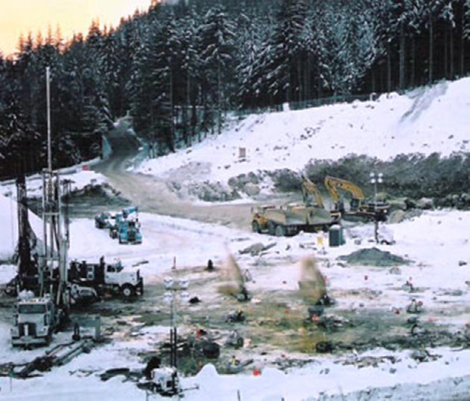
2.7Blasting Inthemethodofblastingforgroundimprovement,whichisalsoknownasexplosive compaction,thesequentialdetonationofexplosivesiscarriedoutincasedboreholes tocausegroundcompaction(Fig.2.7).Theexplosivechargesarespacedverticallyata distanceofabout3–8mintodrilledorjettedholes,whicharekept4–15mapart,and backfilledbeforedetonation.Theexplosivecompactioniseconomicalcomparedto othermethods,particularlywhendoneonalargescale,anditcantreatsoilstoadepth ofupto40m,whichothermethodscannotreach.Twoorthreeroundsofblastingmay berequiredtoachievethedesireddegreeofdensificationataparticularsite.The radiusofinfluenceoftheblasting,R,canbeestimatedusingthefollowingformula:
where M isthemassofexplosivechargesinkgand C isaconstantdependinguponthe typesofexplosiveusedandthegroundconditions.
Inthepast,thistechniqueofblastinghasbeensuccessfullyusedforearthdams, minetailings,bridges,buildings,portfacilities,andoffshoreoilstructures.Blasting ismosteffectiveinloosesandswithasiltcontentof <20%andaclaycontentof <5%. However,themajorlimitationofthismethodisthatduetothestrongvibrationsduring detonation,itmaydamagenearbystructuresormaycausesignificantgroundmovement.Soitisessentialtoseethatthechargesarefiredsequentiallyinaproperpattern thatcanoptimizecompactionwithoutcausingdamagetonearbystructuresandpublic utilities.Moreover,thereshouldbescopefordrainingthelargevolumeofwaterthat mayappearonthesurfaceduetotime-dependentdissipationofexcesswaterpressure producedduringtheprocessofblasting.Keepinginmindthepointsmentionedabove,
Fig.2.7 Blastingor explosivecompactionatthe siteforground improvement(Elliottetal., 2009).
theinstrumentationrequiredforblastingincludes(1)surfacegeophonestomeasure vibrationresponseatcriticallocations,(2)transducerstomeasureresidualporepressuresgeneratedbytheblasting,(3)hydrophonesinstalledinwater-filledcasingsto identifychargedetonations,(4)Sondextubestomeasureatdepththesettlementat thatfollowstheblasting,and(5)inclinometerswhereblastingiscarriedoutnear slopestomeasureslopemovements.
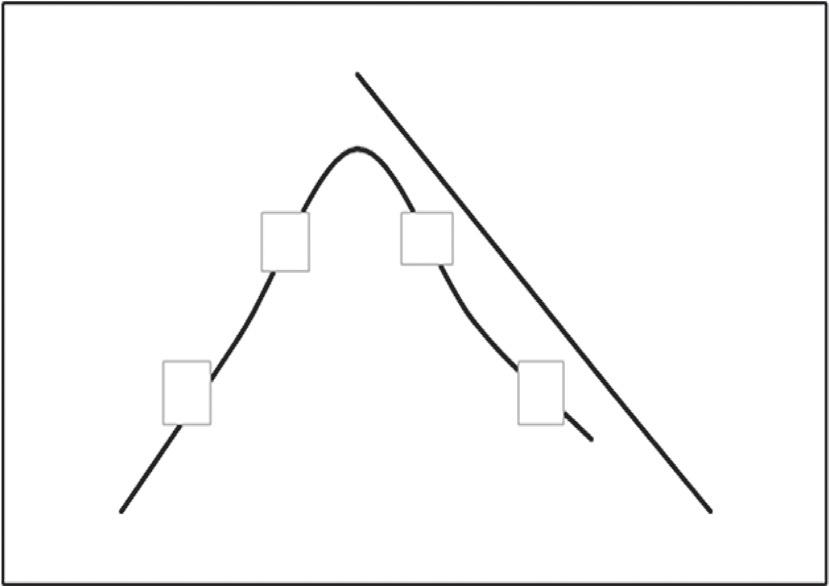
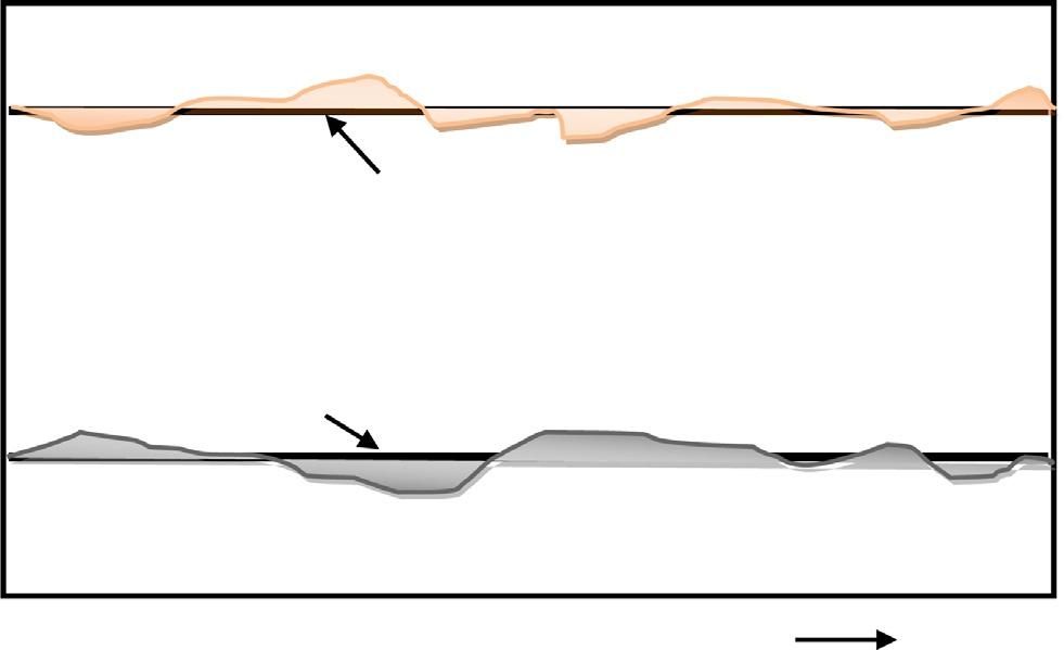
2.8Fieldcompactionanditscontrol Inthissection,thefieldmonitoringofcompactionparticularlyrelatedtotherollers,is discussed.Bydeterminingtherelativedensity(RD),itcanbeascertainedwhetherthe requireddensityhasbeenachievedinthefieldornot.
Thedensitythathasbeenachievedinthefieldcanbeobtainedwiththehelpofvarious instrumentslikesandcone,balloondensometer,Shelby/drivetube,andnucleargauge. Similarly,themoisturecontentisdeterminedusingavarietyofmethodslikenuclear gauge,speedymoisturetester,hotplate,orovendrying.Usingtheseinstruments,the moisturecontentanddensitycanbecheckedatsuitableintervalsalongasection(as shownin Fig.2.8),theresultsofwhicharethenusedtorectifythecompactionprocess (no.ofpasses,liftthickness,weight,operativefrequency,amountofsprinkledwater, soilgradation,etc.)inordertoachievethedesiredresults.Moreover,asmentionedin theprevioussection,GPS-basedsystems,suchasintelligentcompaction,canbeused asaQA/QCtollinthefield.
Goodspecificationsarenecessarytoensureanexpectedlevelofperformanceand forQA/QC.Thespecificationscangenerallybecategorizedas(1)method
Fig.2.8 Compactioncheckalongasectionline.
specifications,(2)resultspecifications,and(3)performancespecifications.The methodspecificationdescribesindetailtheequipmentandprocedurestobefollowed inordertoobtainthedesiredresultinthefield(e.g.compactiveeffortofsixpasses usinga1-tonlightvibratoryrollerwithaworkingspeedof2km/handvibratingfrequencyof50Hzshallbemadeoneach30cmliftofthesoil).Ontheotherhand,the resultspecificationdirectlystatestheresulttobeachievedinthefield(e.g.adrydensityof95%ofMDDasdeterminedbyASTMD698-12e1shallbeobtainedforeach liftofsoil).Theresultspecificationisshorterandeasiertowriteanditallowsthecontractorsomelibertytoinnovatehisorherprocessandhisorherintentionisjusttogive thefinaldesiredresults.Theperformancespecificationdescribestheconstruction qualitycharacteristicsthathavebeendemonstratedtocorrelatesignificantlywith thelong-termperformanceofthestructure(e.g.thepavementshallsupport2million equivalentsingleAxleloadswithoutdevelopingfatiguecracksorrutdepthsexceeding5mm).
Itistobeconcludedinthissectionthatwiththeinclusionofsophisticatedtechnologylikelasers,digitalvideo,imageanalysis,andGPS,theQA/QChasbecomesimple,accurate,andlesstimeconsuming.ConventionalmethodslikeCBR,plateload tests,fallingweightdeflectometer,anddynamicconepenetrationtestsaregradually beingreplacedwiththesenon-conventionalmethods.
Furtherreading Degen,W.S.,1997.56mdeepvibrocompactionatGermanligniteminingarea.In:Proceedings of3rdInternationalConferenceonGroundImprovementGeosystems,pp.128–133, London.
Elliott,R.J.,Clarke,L.,Gohl,B.,Fulop,E.,Singh,N.K.,Berger,K.C.,Huber,F.,2009.ExplosivecompactionoffoundationsoilsfortheseismicupgradeoftheSeymourfallsdam. In:Proceedingsofthe35thAnnualConferenceonExplosivesandBlastingTechnique, InternationalSocietyofExplosivesEngineers,Denver,Colorado,17pp. FederalHighwayAdministration,2004.DynamicCompaction.UniversityPressofthePacific, UnitedStates.
Gohl,W.B.,Jefferies,M.G.,Howie,J.A.,Diggle,D.,2000.Explosivecompaction:design, implementationandeffectiveness.Geotechnique50,657–665. Hogentogler,C.A.,1936.EssentialsofSoilCompaction,ProceedingsHighwayResearch Board.NationalResearchCouncil,Washington,DC,pp.309–316.
Narin,W.,Court,V.,Mitchell,J.K.,1994.Explosivecompaction:densificationofloosesaturatedcohesionlesssoilsbyblasting.In:GeotechnicalEngineeringReportUCB/GT/94-03. UniversityofCalifornia,Berkeley.
Priebe,H.J.,1995.TheDesignofVibroReplacement.GroundEngineering,London.
Soilstabilization 3.1Introduction Thestabilizationprocessreferstothemixingoftwoormoredifferentsoilsortothe mixingofasoilwithanothergeomaterialorwithchemicalsthatcanamenditsgeotechnicalpropertiesaspertheprojectrequirements.Themajorreasonsfordoingsoil stabilizationareasfollows:
l Enhancementofthestrengthandhencebearingcapacity,aswellassomeoftheotherengineeringproperties,ofsoils.
l Dustcontrolforagoodworkingenvironment.
l Waterproofingforconservationofnaturalormanmadestructures.
l Topromotetheuseofwastegeomaterialsinconstructions.
Soilstabilizationisaverycommonprocessforalmostalltheroadprojects.Broadly, alltypesofsoilstabilizationcanbeclassifiedintotwogroups,i.e.mechanicalstabilizationandchemicalstabilization.Inmechanicalstabilization,thegradingofasoilis changedbymixingitwithothertypesofsoilsofdifferentgrades.Bydoingso,a compactedsoilmasscanbeachieved.Ontheotherhand,chemicalstabilizationis associatedwiththemodificationofsoilpropertiesbytheadditionofchemicallyactive materials.Insoilstabilization,itisveryimportanttounderstandthematerialpropertiesinvolvedinthemixtureandtheoutcomeaftermixing.Moreover,itisimportantto findouthowthematerialisgoingtoperformafterstabilization.Atthesametime,the effectsoftheprocessonthenearbystructuresandsurroundingconditionsneedtobe evaluated.Accordingly,decisionscanbetakenontheselectionofmaterialsandthe correspondingdoses.Inadditiontotheselectionofmaterialsandthedoses,thereare manyotherfactorsgoverningtheeffectivenessofthismethode.g.mixingandspreading,selectionofroller,compactionlayerthickness,compactioneffort,sequenceof operation,curing,environmentalandclimaticconditions,etc.
3.2Mechanicalstabilization Asmentionedearlier,theobjectiveofmechanicalstabilizationistoachievedense well-gradedmaterialbymixingandcompactingtwoormoresoilsand/oraggregates. Adetailofthismethodispresentedinthefollowingsections.
3.2.1Mechanism First,byaddingdifferentgradesofmaterialsadense-packedmaterialisachieved. Second,withadditionofasmallamountoffinematerials,i.e.siltsandclays(binder), properbindingofthenoncohesivesoils/aggregateswilltakeplace,whichenhances thestrengthofthematerial.Strong,angularparticlesofsandsandgravels,imparting GeotechnicalInvestigationsandImprovementofGroundConditions. https://doi.org/10.1016/B978-0-12-817048-9.00003-2 © 2019ElsevierInc.Allrightsreserved.
internalfrictionandincompressibilitytothemix,canbewellstabilizedwiththeadditionofasuitabledoseofthebinder.Manyotherlocallyavailablematerials,likemine tailings,coral,shell,clinker,slags,constructiondebris,etc.,havebeensuccessfully stabilizedbyusingthistechnique.Themechanicalstabilityofmixedsoildepends uponseveralfactorslike(i)themechanicalstrengthandpurityoftheconstituentmaterials,(ii)thepercentageofmaterialsanditsgradationinthemix,(iii)thedegreeofsoil bindingtakingplace,(iv)themixing,rolling,andcompactionproceduresadoptedin field,and(v)theenvironmentalandclimaticconditions.Useofgeosyntheticmaterials inmechanicalstabilizationisaparticularmethodwherethesoilstrengthandother engineeringpropertiesarefurtherenhanced(duetoparticlesinterlocking,confinement,frictionalresistance,tensilestrength)withtheinclusionofthegeosynthetic materialslikegeogrids,geotextiles,etc.
3.2.2Proportioningofmaterials Theratioofdifferentsoils/aggregatesinthemixneededtoachievemaximumdensity isknownasproportioning.AspertheFuller’srule,thetheoreticalgradationformaximumdensityisdeterminedas:
where ρ isthepercentageofparticlesfinerthanthesize d (mm), D isthediameterof largestparticle,and n isthegradationindexthatdependsupontheshapeofparticles.
Moreover,thesoils/aggregatescanbemixedonatrialanderrorbasicandthen testedfortherequiredstrengthandotherpropertiesofthemix.Thepercentageof twodifferentmaterials A and B inamixinordertoachieveagradationasperthe specificationcanbeobtainedasfollows:
where Σ a isthesummationoftheabsolutevaluesof S a (a isthepercentagepassing ofmaterial A throughdifferentsizesand S istheaverageofthecorrespondinggradationlimitasperspecification).Inasimilarmanner Σ b isalsodetermined.
Iftherearethreematerialsinthemix,i.e. A, B,and C,thenthepercentofthese materialscanbedeterminedasfollows:
Inasimilarmannerthepercentofmaterialsinanymixcanbedetermined.
Soil B, PI=0
80 60 40 20 02468
Soil A, PI=8
(%) % of material passing 425 µ sieve for Soil A
Soil A (30%) + Soil B (70%) [PI=6.4]
Soil A, LL=28
Soil A (30%) + Soil B (70%) [LL=24]
Soil B, LL=8
(%) 1012140481216202428
Fig.3.1 Plasticitydeterminationofacombinationofsoils(FM5-410).
Ontheotherhand,plasticityofamixcomposedoftwoormoredifferentsoilscan bedeterminedasfollows:
PI ¼ A0 ax + B0 by + C0 cz
A0 a + B0 b + C0 c
where A0 , B0 ,and C0 aretherespectivepercentagesofmaterials A, B,and C; a, b, c are therespectivepercentagesofmaterials A, B,and C passingthrougha425 μ sieve;and x, y,and z aretheplasticityindex(PI)ofmaterials A, B,and C. Plasticityofthemixcanalsobedeterminedgraphically.Forexample,theliquid limit(LL)andPIofamixcomposedoftwodifferentsoils,i.e.30%ofsoil‘A’(having LL ¼ 28andPI ¼8)and70%ofsoil‘B’(havingLL ¼ 8andPI ¼0),ispresentedin
Fig.3.1.Thepercentageofmaterialfinerthan425 μ presentinthesoilwithhigher plasticity(i.e.SoilAinthisexample), P,isobtainedasfollows:
P ¼ QA0 a
QA0 a + QB0 b
where A0 and B0 aretherespectivepercentagesofmaterials A and B inamixofsay Q grams; a and b aretherespectivepercentagesofmaterials A and B passingthrougha 425 μ sieve.
3.3Chemicalstabilization Asmentionedearlier,chemicalstabilizationreferstothealterationofsoilproperties bychangingitschemicalmake-upwithdifferentadditiveslikelime,cement,flyash, etc.,orbytheadditionofchemicals,resins,andenzymes.
3.3.1Mechanism AroraandScott(1974) havereported18differentchemicalmechanisms(i.e. exchangeofcations,exchangeofanions,adsorption,fixation,formationofnewminerals,cementation,saltconversion,modificationofwaterfilms,adsorptionofwater films,enrichmentofporewaterwithions,modificationofcapillaryforces,modificationoftheelectricalsurfacetensionofclayminerals,modificationoftheelectrical forcesbetweenparticles,modificationofchemicallyboundwater,adsorptionof chemicallyboundwater,neutralizationofacids,neutralizationofbases,andproton exchange),thatmaycausestabilizationofclays.Further,theflocculationofparticles, generationofheatduringchemicalreactions,etc.,maytakeplace.Oneoracombinationofthesemechanismsmaytakeplacedependinguponthetypesoftheadditives mixedwiththesoils.
3.3.2Limestabilization Theadditionoflimeisasuitabletechniqueforthestabilizationoffine-grainedsoils. Thelimemaybeusedindifferentforms,e.g.hydratedhigh-calciumlime, monohydrateddolomiticlime,calciticquicklime,anddolomiticquicklime.Thecalciuminthelimeexchangeswiththeadsorbedcationsoftheclaymineralcausingthe claytoflocculate,andthusreducingthePIofclays.Inthiswayclaysbecomemore workableandmixable.Theswellingpotentialofclaysalsodecreaseswiththeaddition oflime.Moreover,withconsumptionofwaterandgenerationofheatduringhydration ofquicklime,thesoilbecomesmorerigid.LimeincreasesthepHvalueofsoilpore waterreleasingsilicafromtheclaymineral.Thereleasedsilicathenreactswiththe calcium(presentinlime)toproducecement,whichstrengthensthesoilwithproper curingofthemix.
Therequiredlimecontentcanbedeterminedonatrialanderrorbasis,keepingin viewthestrengthrequirementofthetreatedsoils.Quicklimeismorereactiveascomparedtothehydratedlime.Henceifquicklimeisusedthequantitycanbereducedto 75%ofthehydratedlime.AspertheEadesandGrimtestmethod(ASTMC977-02), ifthepHreadingsare12.40orhigher,thelowestpercentagethatgivesapHof12.40is thepercentagerequiredtostabilizethesoil.IfthepHreadingsdonotgobeyondapH of12.30andtwopercentagesgivethisreading,thelowestpercentagetogiveapHof 12.30isthepercentagerequiredtostabilizethesoil.IfthehighestpHreadingisapH of12.30andonlythehighestpercentagelimeusedgivesapHof12.30,additional testingisrequiredusinghigherpercentagesoflime.
Limestabilizationisparticularlyusedin roadprojectsformodifyingthepropertiesofsubgradesoils,subbasematerials,andbasematerials.Inadditiontothe enhancementofstrength,limestabilizatio nalsoimprovesthematerialresistance tofracture,fatigue,andpermanentdeformation.Inaddition,limeisoftenused incombinationwithotheradditiveslikecementandbitumentocompensatefor thedeficiencyofeachotherortoincrease theeffectivenessofthestabilization process.