FeedstockTechnology forReactiveMetal InjectionMolding
PENGCAO
DepartmentofChemicalandMaterialsEngineering, TheUniversityofAuckland,Auckland,NewZealand
MUHAMMADDILAWERHAYAT
Elsevier
Radarweg29,POBox211,1000AEAmsterdam,Netherlands TheBoulevard,LangfordLane,Kidlington,OxfordOX51GB,UnitedKingdom 50HampshireStreet,5thFloor,Cambridge,MA02139,UnitedStates
Copyright©2020ElsevierInc.Allrightsreserved.
Nopartofthispublicationmaybereproducedortransmittedinanyformorbyanymeans, electronicormechanical,includingphotocopying,recording,oranyinformationstorageand retrievalsystem,withoutpermissioninwritingfromthepublisher.Detailsonhowtoseek permission,furtherinformationaboutthePublisher’spermissionspoliciesandour arrangementswithorganizationssuchastheCopyrightClearanceCenterandtheCopyright LicensingAgency,canbefoundatourwebsite: www.elsevier.com/permissions
Thisbookandtheindividualcontributionscontainedinitareprotectedundercopyrightby thePublisher(otherthanasmaybenotedherein).
Notices
Knowledgeandbestpracticeinthisfieldareconstantlychanging.Asnewresearchand experiencebroadenourunderstanding,changesinresearchmethods,professionalpractices, ormedicaltreatmentmaybecomenecessary.
Practitionersandresearchersmustalwaysrelyontheirownexperienceandknowledgein evaluatingandusinganyinformation,methods,compounds,orexperimentsdescribed herein.Inusingsuchinformationormethodstheyshouldbemindfuloftheirownsafety andthesafetyofothers,includingpartiesforwhomtheyhaveaprofessionalresponsibility.
Tothefullestextentofthelaw,neitherthePublishernortheauthors,contributors,or editors,assumeanyliabilityforanyinjuryand/ordamagetopersonsorpropertyasamatter ofproductsliability,negligenceorotherwise,orfromanyuseoroperationofanymethods, products,instructions,orideascontainedinthematerialherein.
BritishLibraryCataloguing-in-PublicationData
AcataloguerecordforthisbookisavailablefromtheBritishLibrary
LibraryofCongressCataloging-in-PublicationData
AcatalogrecordforthisbookisavailablefromtheLibraryofCongress
ISBN:978-0-12-817501-9
ForInformationonallElsevierpublications visitourwebsiteat https://www.elsevier.com/books-and-journals
Publisher: MatthewDeans
AcquisitionsEditor: ChristinaGifford
EditorialProjectManager: AnaClaudiaA.Garcia
ProductionProjectManager: SojanP.Pazhayattil
CoverDesigner: MarkRogers
TypesetbyMPSLimited,Chennai,India
Contents
1.Reactivepowdermetalinjectionmolding1
1.1 Metalinjectionmolding astandoutmanufacturingtechnology?1
1.2 Overviewofmetalinjectionmolding1
1.3 Evolutionofmetalinjectionmoldingtechnology13
1.4 Opportunitiesformetalinjectionmoldingofreactivemetals23
1.5 Constraintsonthereactivepowdersmetalinjectionmolding35 References39
2.Designstrategyofbindersystemsandfeedstockchemistry43
2.1 Theroleofbinder43
2.2 Basicsofbinder45
2.3 Feedstockchemistryandproperties64
2.4 Summary81 References81
3.Bindersysteminteractionsandtheireffects87
3.1 Interactionsbetweenbindercomponents87
3.2 Interactionsbetweenpowderandbinder127
3.3 Summary136 References138
4.Impuritymanagementinreactivemetalsinjectionmolding145
4.1 Theimportanceofimpuritycontrol145
4.2 Methodsofcontrollingimpurities147
4.3 Pointstoconsiderforotherreactivepowdersmetalinjectionmolding170
4.4 Processcontrol183
4.5 Summary185 References186
5.Potentialfeedstockcompositionsformetalinjectionmolding ofreactivemetals191
5.1 Polymersthatthermallydegradebydepolymerization191
5.2 MinimizingoxidationinAlorMg-MIM195
5.3 Commercialfeedstocksandtheirproperties207
Reactivepowdermetalinjection molding
1.1Metalinjectionmolding—astandoutmanufacturing technology?
Themarketofmetalinjectionmolding(MIM)hasexpandedsignificantly overthelastdecadestoincludeabroadarrayofapplicationssuchasconsumerelectronics,automotive,medical,andfirearms.MIMfabrication resultsfromtheapplicationofplasticinjectionmoldingtechnologyto powdermetallurgy.Itisalow-costformingmethodbestsuitedforthe metalsandalloysthataredifficulttomachineorcast.Theprocessisused tomakesmall-to-mediumandcomplex-shapedpartsfrommetaloralloy powdersandreliesonshapingmetalparticlesandsubsequentlysintering thoseparticles.Hence,theprocessiscapableofproducingpartshaving higherstrengthcomparedwithdiecasting,improvedtolerancescompared withinvestmentorsandcasting,andmoreshapecomplexitycompared withmostotherformingroutes.Thecompetitiveadvantagecomesfrom theabilityofMIMtomanufacturecomplexpartsathighproductionrates andnear-net-shapingcapability,whichresultsinhighyieldsavings.
Conventionalproductionprocessesarebeingincreasinglyreplacedby MIM machining,casting,andpress-sinteringaresomeoftheprocesses thathavebeenreplacedbyMIM.
1.2Overviewofmetalinjectionmolding
1.2.1Metalinjectionmoldingprocesses
Althoughpowderinjectionmolding(PIM)wasfirstdemonstratedduring the1930swhentheceramicsparkplugbodieswereproduced,MIMdid notachievecommercialstatusuntilthe1970s.Thedelaywasduetothe lackofsophisticationintheprocessequipment.Withtheadventof microprocessor-controlledprocessingequipment,suchasmoldersandsinteringfurnaces,whichenabledrepeatableanddefect-freecycleswithtight
tolerances,themanufacturinginfrastructureoftheMIMstrategy improveddramatically.1
MIMattractedmajorattentionin1979whentwodesignawardswere won.OneawardwasforascrewsealusedonaBoeingjetliner.Thesecondawardwasforaniobium-alloythrustchamberandinjectionfora liquid-propellantrocketengine.2 Theseawardsprovidedthenecessary springboardforextensiveresearchinthisfield.Severalpatentsemerged, withoneofthemostusefulbeingissuedin1980toRayWiech.From thisbeginning,ahostofotherpatents,applications,andfirmsstrictlydealingwithMIMrose.Bythemiddle1980s,theMIMtechnologyhad developedafirmbaseinthemanufacturingsector.Sincethemid-1990s, theMIMtechnologyhasexpandedtoincludeanarrayofdifferentmaterialfamiliesandnewandinnovativeproductdesignsthatwerenotpossiblewithconventionalprocessing.
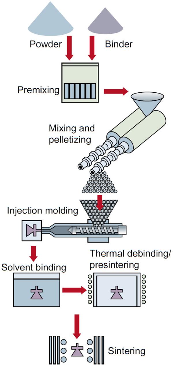
ThekeystepsofMIMinclude(1)selectingandtailoringapowderfor theprocess;(2)mixingmetallicpowderandabindersystemtoforma homogenousfeedstock;(3)moldingthefeedstocktoachievetherequired shapeandgeometry(greenparts);(4)removalofthebinderwhilekeeping thegeometry(debinding);(5)sinteringthedeboundparts(brownparts) toachievethedesiredmechanicalproperties;and(6)postsinteringtreatmentstofurtherimprovepropertiesifrequired.Thestepsinvolvedinthe MIMareillustratedin Fig.1.1.
MIMcanprocessanymetalifthemetalisproducedina suitablepowderform.SomecommonmaterialfamiliesusedinMIMare stainlesssteel,lowalloysteel,toolsteel,titanium,copper,tungsten,and hardmetals.MIMproducts'mechanicalpropertiesaresuperiortocast productsinmostcasesandslightlyinferiortowroughtproducts.Castand MIMcomponentsbothhavesomemicrostructuralvoidsasaresultofthe processingmethods.Thecastvoidsareusuallylargeduetothecoolingof liquidtosolidwhiletheMIMvoidsaretypicallyfineandwelldistributed acrossthemicrostructureaftersintering.ThelargevoidsofthecastcomponentsresultintheinferiorpropertiesthanMIMcomponents.Evenfull densification(microstructurewithoutvoids)canbeattainedinMIMby postsinteringtechniquessuchashotisostaticpressing.Thedimensional variabilityoftheMIMprocessisassociatedwiththeamountofshrinkage thatthecomponentexperiencesduringthedebindingandsintering. Componentsshrinkabout1%duringthedebindingoperationandabout 15% 25%aftersintering.
1.2.2Designconsideration
Beforeselectingthistechnology,capitalinvestment,productioncosts, productionrateaswellasperformanceandqualityofthepartarethefactorsthatneedtobetakenintoconsideration.Asageneralruleofthumb, componentsthatareproducedbypressandsintertechnology(generally lessthan100g)canbeeasilymanufacturedbyMIM.Typically,anaveragesizeof15giscommonforaMIMcomponent;however,componentsintherangearound0.030garealsopossible.4 Table1.1 presents thelowerandupperspecificationsoftheMIMprocess.
MIMprocessgenerallyproducesgoodsurfacefinish.Typically,the surfacefinishof0.8 μmcanbeachievedeasily.However,surfacefinishas smoothas0.3 μmisalsopossible.Thesurfacefinishgenerallydependson thechemistryofpowdersusedandthesinteringconditions.
Figure1.1 StepsinvolvedinaMIMoperation.3
Table1.1 TypicalattributesproducedbytheMIMprocess.
AttributesMinimumTypicalMaximum
Componentmass(g)0.03010 15300
Max.dimension(mm)225150
Min.wallthickness(mm)0.025515
Tolerance(%)0.20.51
Density(%)9398100
Productionquantity1000100,000100,000,000
Surfacefinish(μm)0.30.81
AsMIMinvolvespostmoldingstepsofdebindingandsintering,there aresomedesignrecommendationsthatshouldbeconsideredtogethighqualityMIMproduct,aslisted:
1. Avoidcomponentsover12.5mmthick.Incaseswherethicksections aredesired,specialmodificationstothebindersystemshouldbemade todebindthicksections.
2. Avoidcomponentsover100ginmass.
3. Avoidholessmallerthan0.1mmindiameter.
4. Avoidwallthinnerthan0.1mm.
5. Maintainuniformwallthicknessinordertoattainsmoothflowduring molding.
6. Avoidsharpcorners.Thedesiredradiusisgreaterthan0.05mm.
7. Avoidinternalundercuts.
8. Designwithaflatsurfacetoaidinsintering.
1.2.3Powdersformetalinjectionmolding
Powdersshape,size,anditsdistributionplayadecisiveroleindetermining theoverallqualityoftheMIMproduct.Metalsoralloypowdersthatcan bemanufacturedtoasufficientlysmallsize( , 45 μm),sinterable,anddo notpossessameltingpointlowerthanthedecompositiontemperatureof thebinderscanbeutilizedforMIM.Thelow-meltingtemperatureand strongsurfaceoxidesandtheirinterferencewithsinteringmakealuminum andmagnesiumlessdesirableforMIM.However,bothhavebeensuccessfullyprocessedbyMIMwithlimitedcommercialsuccess.5 More detailsonAlandMg-MIMcanbefoundinChapter4,Impurity ManagementinReactiveMetalsInjectionMolding,andChapter5, PotentialFeedstockCompositionsforMIMofReactiveMetals,ofthis book.CommonMIMmetalsandalloysincludestainlesssteel,low-alloy
steels,toolsteels,copperanditsalloys,titaniumanditsalloys,softmagneticalloys,refractorymetals,andcementedcarbides.TheidealMIM powdercharacteristicsareasfollows6 8 :
1. Powderparticlesize(D90)of , 22 μmformostofthemetalsand alloysforgoodsinterabilityandsurfacefinishsincefinerpowderssinter morereadilythancoarserpowders.However,forreactivepowder suchastitanium,thislimitcanbesetat # 45 μmastheriskofimpuritypick-upduringsinteringalsoincreaseswithahighersurfacearea ofthefineparticles.Inaddition,forreactivepowders(titanium,aluminum,magnesium,andzirconium),theprobabilityofexplosion increasessimultaneouslywithdecreasingparticlesize.
2. Itisoftensoughttoincorporateahighproportionofmetalpowderinthe feedstock.Inotherwords,powdershavingahighpackingdensityaredesirable.Thesphericalornear-sphericalshapeshould,therefore,bepreferred (seeChapter2:DesignStrategyofBinderSystemsandFeedstock Chemistryformoredetails).However,irregularshapepowdersinthecase oftitaniumanditsalloyshavealsobeenwidelystudiedastheyoffermuch lowercost(B45$/kg)comparedtosphericalpowders(B250$/kg).
3. Thepowderparticlesshouldhavehighsurfacepuritytomaintainuniforminteractionwiththebindersystem.
4. Thepowderparticlesshouldbevoid-free.
Table1.2 comparesthedifferentpowderproductionmethodswith respecttoprice,shape,size,andmaterialsthatcanbeprocessed.
High-purityargonatomizationistheprincipaltechniqueusedtoproducereactivemetalspowders.However,aluminumpowdersarealsoproducedviaairatomization.Otherfabricationtechniques,suchasplasma atomization,arealsosometimesusedforreactivemetalspowder production.
Table1.2 CommontechniquesforpowdersproductioninMIM.
TechniqueSize(μm) approx.
ShapeMaterialsCost
Gasatomization5 45SphericalMetals,alloysHigh Wateratomization5 45Semispherical Metals,alloys exceptreactive Moderate Thermal decomposition 0.2 20Sphericalto spiky MetalsonlyModerate
Chemical reduction 0.1 10Angular, spherical MetalsonlyModerate tohigh
1.2.4Binderselection
ThebindersystemisanintegralpartoftheMIMprocess.Itcontrolsthe shapingstageoftheMIMprocessandthenholdsthepowderparticles untiltheinitialstageofsintering.Byachievingthis,abindersystemusuallyhasthreecomponents:alowmolecularweightcomponentthatprovidesthenecessaryflowabilityduringmolding,abackbonepolymerthat providesthegreenstrength,andasurfactantwhichactsasabridge betweenthebinderandpowderparticles(seeChapter2:DesignStrategy ofBinderSystemsandFeedstockChemistryformoredetails).Somecommonbindersystemsarelistedin Table1.3 9,10
Thermoplasticandthermosettingaretwocommontypesofpolymers. Thermoplasticpolymersareformedbyrepeatingsmallmonomergroups alongthechainlengthwithoutcross-linking.Ontheotherhand,inthermosettingpolymers,monomersundergocross-linking,whichresultsin theformationofathree-dimensionalrigidstructure.Thecross-linkingof thermosettingpolymersuponheatingcanbehelpfulduringthemolding processsinceitmayprovidethenecessarygreenstrength.However,due totheircomplicateddecompositionprocesses,thermosettingpolymersare rarelyusedinMIM.
Thecompositionofthebinderplaysasignificantroleindetermining thebinderviscosityandflowbehavior,especiallyformixtureswithlarge differencesinviscositiesamongthecomponents.Viscosityincreasesasthe molecularweightisincreased,soaproperselectionofthemolecular weightofeachbindercomponentisnecessary.FortitaniumMIM,careful
Table1.3 Commonbindersystemsformetalinjectionmolding. BindertypeMainingredientsPolymerbackboneAdditives
ThermoplasticWaxes(paraffin/ microcrystalline/ carnauba/natural waxes),oils (vegetable/peanut oil),acetanilide, naphthalene,PEG
PE,PP,PS,PA, PVB,HDPE, LDPE,PBMA, CAB,EVA, PMMA
Stearic/oleic acid,oils
PolyacetalPolyoxymethyleneProprietary ThermosettingEpoxyresinWaxesStearicacid
GelationWaterMethylcellulose, agar Glycerine, boricacid
selectionofbindercomponentsisextremelyimportant(discussedmorein detailinChapter2:DesignStrategyofBinderSystemsandFeedstock Chemistry)becausetitaniumisextremelyreactivetoelementssuchasO, N,andC.
1.2.5Feedstockpreparation
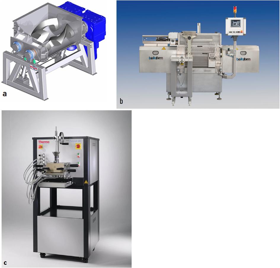
Inthenextstep,themetaloralloypowdersaremixedwithpreselected binderstoproduceahomogeneousmixture alsoknownasafeedstock. Themixingoperationshouldbethoroughenoughtoensurethateach particleiscoatedwiththeselectedbinder.Also,homogeneousmixingof feedstockiscrucialtothefinalproductquality,asanyinhomogeneities suchasbubbles,binderpockets,andpowdersegregationwillsubsequently becarriedovertotheinjectionmoldingstage.Toensurethis,different typesofshearmixersareavailableinthemarketnowadays.Theseinclude twin-screwextruder,doubleplanetary,singlescrewextruder,plunger extruder,twin-camextruder,shearrollcompounder,andmostcommon sigmaorz-blademixers.Someofthecommonmixersareshownin Fig.1.2.
Figure1.2 Somecommonmixers/kneadersusedinfeedstockpreparation:(A)azbladesigmamixer,11 (B)ashearroller,12 and(C)torquemixer.13 (B)CourtesyMr. FrankLanger,BellaformGmbH,Germany;(C)courtesyHAAKEThermoFisherScientific.
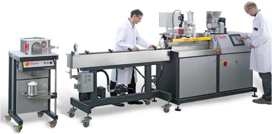
WiththerecentadvancementsinMIMtechnologyandabetterunderstandingoftheprocess,somecompaniessuchasThermoFisherScientific offerawiderangeoffeedstockpreparationequipmentfromlaboratory-scale simplemixingtoindustrial-scalecompoundingandpelletizing, Fig.1.3
1.2.6Moldingoperation
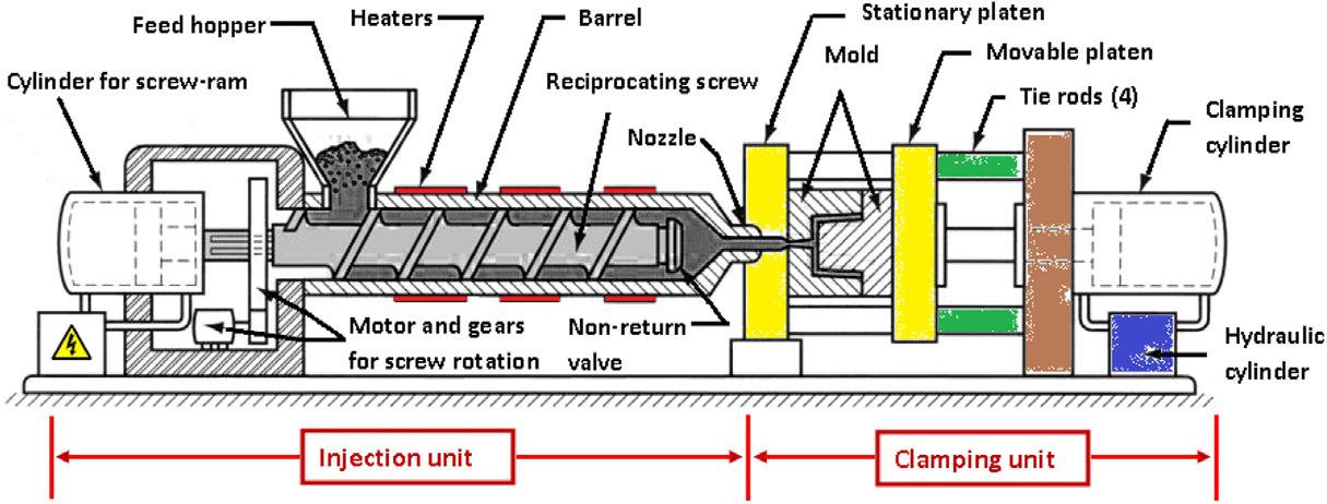
Thedesignofinjectionmoldingmachinesirrespectiveofthesuppliershas certaingeneraldesignfeaturesincommon,whicharenecessarytocarryout andcontroltheinjectionmoldingprocess.Themostimportantcomponents oftheinjectionmoldingmachinearetheinjectionunit,theclampingunit, andthetoolingattachedtotheclampingunit(Fig.1.4).Theseunitsare generallyplacedhorizontally.Infact,themaximumclampingforceisthe maincharacteristicbywhichthepowerandsizeofaninjectionmolding machinearedefined.Moldingparameterssuchasinjectionpressure,injectionspeed,moldquality,andmoldtemperatureareveryimportantforpreparingpartswithoutdefectsandminimumporosity.
Figure1.3 Classicstrandpelletizing.14 CourtesyThermoFisherScientific.
Figure1.4 Aschematicoverviewofinjectionmoldingmachine.15
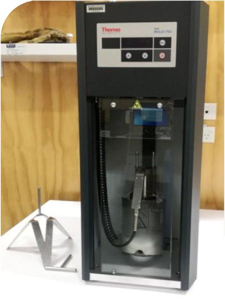
Figure1.5 HAAKEMiniJetpropistoninjectionmoldingsystembyThermoFisher Scientific.Suchsmallinjectionmoldersprovideanexcellentopportunitytotest-run feedstocksonalaboratoryscale.
Barreltemperatureisveryimportant;ifthetemperatureistoolow, thefeedstockmayfreezebeforethemoldcavityiscompletelyfilled.Ifthe temperatureistoohigh,itwillleadtoverylowviscositythatcausesproblemssuchasmoltenfeedstockdrippingoutofthenozzle,flashing,and prolongedcoolingtimes.Itshouldalsobeconsideredthatsomeheatis generatedinthebarrelbythefrictionalforcesbetweenthescrewandthe feedstock.Typicalmelttemperaturesforcommonwax-polymerssystems arebetween150°Cand190°C,andthemoldtemperatureis25°C 55° C.Typicalmelttemperaturesforcatalyticsystemsare200°C 260°C,and themoldtemperatureis100°C 150°C.
Owingtothehigherthermalconductivityofthefeedstock,MIM injectionspeedsaretypicallyhigherthanpurepolymers.Theinjection speedistypicallysetattheminimuminjectionspeedrequiredto completelyfillthecomponent'scavitywithoutanydefects.Toolowan injectionspeedwillresultinsurfaceimperfectionssuchasflowlinesand incompletefill.Toohighaninjectionspeedwillresultinaflashdueto powder/binderseparationandcanresultinanexplosioninthecaseof reactivepowders.
Thesedaysevensmallbench-topinjectionmoldersarealsoavailable inthemarket, Fig.1.5.
1.2.7Debinding
Aftertheinjectionmoldingstep,thebindersystembecomesadisposable componentandhence,mustberemovedfromthesamples.During
debindingoperation,specialattentionispaidtotheshaperetentionofthe moldedsamples.Themethodofbinderremovalhasaconsiderableeffect onthemoldedsampleshaperetention,uniformityofshrinkage,andfinal productmechanicalproperties.Thereforeproperselectionofthedebindingmethodisimportantforgoodqualitycontrol,particularlyforreactive materialssuchastitanium,asexplainedinChapter2,DesignStrategyof BinderSystemsandFeedstockChemistry.Themostcommonlyapplied debindingtechniquesincludethermaldebinding,vacuumdebinding,catalyticdebinding,andsolvent-thermaldebinding.Thesolventdebinding, combinedwiththermaldebinding,isthemostwidelyusedtechniquein theMIMindustry.Itinvolvestwosteps:(1)removalofprimarybinder usuallybysolventdissolution,(2)removalofbackbonepolymer,andsurfactantbyathermalprocesswithoutcrackingordegradingthemolded part.Someoftheimportantpointsthatmustbeconsideredduring solvent-thermaldebindingaresummarizedbelow:
1. Thedissolutionrateoftheprimarybinderinthesolventincreasesas theprimarybinderisliquefied.Thisimpliesthetemperatureofthe solventmustbechosenwithgreatcare.
2. Thereactionofthebackbonepolymerwiththesolventshouldnot causeanypartdistortion.
3. Thesolventshouldnothavehighvaporpressureatdebindingtemperatures.Caremustbetakenifanyofthefirehazardsolventsare used.
Whentheprimarybindersareremoved,nodiffusionbonding betweenpowderparticlestakesplace,asthefirst-stepdebindingisusually performedatlowtemperatures.Itisthebackbonebindersandinterparticlefrictionthatholdthepowderparticlestogetherandmaintaintheshape afterthesolventdebinding.Thesecondarybindersareremovedthermally atmoderate-to-hightemperaturesandcalledthermaldebinding.The thermaldebindingisachievedbyheatingthepartsslowlytothetemperaturewherethesecondarybinderevaporates.Atthosetemperatures,interparticlediffusionisenoughtoholdthepartstogether.16 Table1.4 presentsmultiplebindersystemswiththeirdebindingmethod,debinding temperature,andapproximatedebindingratesforregularMIMparts.17
Anotherattractiveandinnovativemethodforextractingwaxesfrom themoldedsamplesistousesupercriticalsolventdebinding.Inthisprocess, 18 thewaxesareremovedusingliquidCO2 asthesolventatabout 50°C 70°C.Whatmakesthisprocessattractiveisthefastdissolution ofthewax(insomecases,completeremovalofparaffinwaxwasachieved
Table1.4 Examplesofdebindingratesoftheprimarycomponentfordifferent bindersystems.
Primary binder
Secondary binder
Primarydebinding method
(mm/h)
ParaffinwaxPolypropyleneHeptane501.5
Synthetic wax
Polyethylene glycol
Polyethylene glycol
PolypropylenePerchloroethylene702
PolyacetalWater600.5
Polymethy methacrylate
Water500.2
PolyacetalPolyethyleneNitricacid catalyst
1201.5
Itisworthmentioningherethatthesedebindingratesarejustanestimate.Actualdebindingratesmaygreatlyvary dependingonthepowderparticlesize,debindingtemperature,molecularweightoftheprimarycomponent,andits interactionswithmetalpowderandtheothercomponentsofthebindersystem.
in2h19).Afterthesoakingprocess,theliquidCO2 isremovedfromthe chamber,thewaxesareleftbehindinthesolidformandcanbeeasily removed.Asahighpressure(ashighas35MPa)isrequiredtokeepCO2 liquidatthesetemperatures,specialhigh-pressurevesselsarerequiredfor thispurpose.Thereforethisprocesshasnotseencommercialsuccess.17
1.2.8Sintering
Anyleft-overbinderresidueissubsequentlyremovedduringthesintering stepofMIM.Duringsintering,thecomponentshrinkstoformadense shapeandattainahighdensityapprox.96% 99%ofthatofwrought material.Duringsinteringdensification,severalmaterialtransportmechanismsmaybeactive,suchassurfacediffusion,vaportransport,boundary diffusion,andlatticediffusion,allofwhichleadtothereductioninsurface energy.Surfacediffusionandvaportransportaresurfacetransport mechanismsandmainlyrelatedtoparticlecoarsening.Theypromotethe neckgrowthamongtheparticleswithoutincreasingthedensityofthe compact,asonlyparticlesurfacesareinvolved.Densityisincreasedbythe bulktransportmechanisms,whichincludelattice(volume)diffusion, boundarydiffusion,plasticflow,andviscousflow.Dependingonthetype ofmaterialbeingsintered,oneormoreofthesemechanismsmaybe activeduringthesintering.
Thedeboundpartsaresinteredineitheracontinuousorabatch-type high-temperaturefurnace.Thesinteringparameterssuchastemperature, atmosphere,heatingandcoolingrate,andholdingtimeareselectedbased onmaterialtype,composition,andsizeofthepartbeingsintered.For example,thepreferredsinteringconditionsfortoolsteelH11areasinteringtemperatureof1200°C 1275°CandunderN2 atmosphere.
Forreactivemetallicpowders,itisnotpossibletoavoidoxygenpickupentirelyduringsintering.However,theoxygenpickupcanbekeptto aminimumbyusingahighvacuum,generally . 10 2 Pa.Highpurity argoncanalsobeusedasasinteringatmosphere,butitleadstolowersintereddensityduetotrappingofgasinthepores.
Theselectionofsinteringparametersforreactivepowdersisatough taskandisalwaysacompromisebetweenlowcontentsofimpurity,low residualporosity,andsmallgrains.Generallyspeaking,highersintering temperaturesandlongerholdingtimesleadtoahigherdensityandresult inhigherstrength.Onthecontrary,ahighersinteringtemperaturealso leadstomoreoxygencontaminationandhenceincreasedbrittleness. Moreover,italsoleadstograincoarsening,whichisdetrimentalto strength.Thereforetheoptimalsinteringcycleforreactivepowders dependsonthestartingpowdercharacteristics,desireddensity,alloying approach,microstructure,andfinalimpuritylevelrequirements.
Assinteringtemperaturesareusua llyclosetothemeltingrangeof thecomponent ’ smaterialand,insomecases,alsoinvolvealiquid phase,theselectionofchargecarriers(alsoknownasrackingmaterials) isextremelyimportant.Topreventanyreactionbetweenthecomponentandthechargecarriers,alayerofinertceramicisusedasabarrier betweenthetwo.Thechargecarryingshelvesinagraphitefurnaceare usuallyalsographite.Directcontactofthesegraphitechargecarriers wouldresultintheformationofalowmeltingeutecticinseveralmaterialsystems.Inthecaseofrefracto rymetalfurnaces,molybdenum(Mo) oramolybdenumalloyisusedasshelvingmaterial.However,Mo reactswithferrousmaterialstoformaliquidphase.Hence,anonreactivebarrierisamusttopreventtheunwantedreactionirrespectiveof thefurnacetype.
Aluminaisawidelyusedchargecarrierformostofthematerials exceptfortitaniumalloysbecausetitaniumreactswithalumina.Fortitanium,themostsuitableandsuccessfulcarriermaterialsarezirconia(ZrO2) andyttria(Y2O3).Zirconiastabilizedyttria(YSZ)isalsoamongthebest. High-purityyttriaplateshavealsobeenused,buttheseareevenmore
expensiveanddifficulttosourcethantheYSZplates.Theonlymetalthat canbeusedassinteringsupportismolybdenum.
1.3Evolutionofmetalinjectionmoldingtechnology
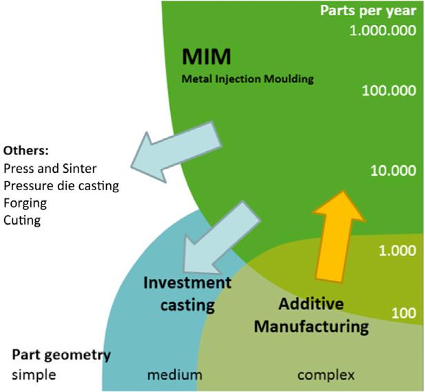
MIMtechnologyhassignificantadvantagesoverconventionalmachining andwroughttechnologiessuchasdiecastingandinvestmentcasting whenitcomestoproducingsmallandcomplexcomponentsinmediumto-highvolumes(Fig.1.6).Thecostadvantagedependsonthecomponentmaterial,shapeandsize,andproductionvolumes.Someofthekey benefitsarelisted:
Itisnear-net-shapemanufacturingforcomplexgeometries
Itminimizesmaterialwastageandreducesfinishingrequirements Itcancombinemultiplecomponentsintoone,thusreducingpart andassemblycosts.
Itreducescostsduetolowerrawmaterialconsumption.
1.3.1Materialsdevelopment
Fromthepast2decades,researchstudiesarebeingcarriedouttomanufactureandtestnewmaterialssystemsviaMIM.Theseresearchefforts haveledtosettingupofmanyindustrialcollaborationsandcompanies thatcansupplycommercialfeedstocksandcancreateproprietaryrecipes fortheclients.21,22 Forinstance,theinternationallyactivefamilycompany OBEOhnmacht&BaumgaertnerGmbH&CoKG22 forlarge-scale manufacturingofprecisionmechanicalmetalpartshassetupaMIMplus
Figure1.6 DiagramshowingwhereMIMismostappropriatelyusedincomparison withotherfabricationprocesses.20
researchanddevelopmentdepartment.Thisdepartmentisfocusedon developinginnovativeandnewMIMmaterialsthatarenotavailableso far.Thisincludespermanentmagneticalloys(e.g.,NdFeB)orcomplex compositematerials.
TheattractivefeaturesoftheMIMprocesscanbeappliedadvantageouslytothefabricationofmetalmatrixcomposite(MMC),particularly theparticulatereinforcedMMCs.AlthoughmanyMMCsofferunique propertiesthatcannotbeachievedbymonolithicmetalsoralloys,the highcostofmanufacturingoftenrestrictstheircommercialuses.BysuccessfullyapplyingtheMIMstrategy,thecostforcommercialuseofcompositematerialscanbesignificantlyreduced.Inrecentyears, comprehensiveworkhasbeencarriedouttoexplorethepotentialof MIMforthefabricationofMMCcomponents.23 Manycompanieshave beenworkingtowardidentifyingthecommercialcapacityoftheMIM technologyforthefabricationofcomposites.22,24,25 Thewidelystudied andresearchonMMCsincludestainlesssteels,refractorymetals,intermetalliccompounds,andtitaniumalloyscomposites.AlthoughMMCscan beeithercontinuouslyordiscontinuouslyreinforced,theflowandmold fillingrequirementsoftheMIMprocessascertainthatitismostapplicable forprocessingthefeedstockcontainingparticlesorshortfibers.Thereof, alloftheMMCsfabricatedbyMIMtodatearestrengthenedbydiscontinuousreinforcements.
Intheearly2000s,Thianetal. 26 28 ledtheresearchinexploring thefabricationoftitanium-hydro xyapatite(HA)compositesbyMIM, focusingapplicationsinthebiome dicalfield.TheuseofTi-HAcompositesforbiomedicalapplicationshasincreasedduetotheresulting advantageouscombinationofHAbio activityandfavorablemechanical propertiesofTi.HA(Ca 10 (PO 4 ) 6 (OH) 2 )isabioceramicmaterialfrequentlyusedforimplantsofhumanhardtissuebecauseitschemicaland crystallographicstructureissimila rtothatofboneminerals.Moreover, HAisnontoxic,bioactive,andbioc ompatible,whichresultsinbetter osseointegrationbetweenimplantsandbones.However,amajorlimitationofusingHAisitspoormechanicalproperties.Onthecontrary,Ti hassuperiormechanicalpropertie sandisconsideredabiocompatible metal althoughitsbiocompatibilityisnotasgoodasthatofHA. Consequently,tocreatehigh-efficiencybiomaterialsformedical implants,Ti-HAcompositeshave beenconsideredanencouraging groupofmaterials.Sincetheearly researchonHA/Ticomposites,new studieshavebeencarriedouttostudythesecompositesmadeby
MIM. 29,30 Duringthehigh-temperaturesinteringofHA/Ticomposites,akeychallengeistopreventHAfromdecomposing.Thedegree ofHAdecompositionincreaseswithsinteringtemperature.Onthe contrary,toachieveahighdegreeofdensification,arelativelyhighsinteringtemperatureisrequired.Thisdilemmaisoneofthemainreasons thatishinderingthecommercialsu ccessofthiscompositesystemmade byMIM.
AnothermajorchallengeforusingTi-MIMtomanufactureorthopedicdevicesisthatconventionalTi-MIMcomponentsdonothaveadequatefatiguestrengthformostload-bearingapplications.Typicalfatigue strengths,whenmeasuredbyrotating-beamfatiguetestingarearound 480MPaat10millioncycles.Thecommonlyacceptedminimumfor load-bearingapplicationsis,however,around620MPaat10million cycles.Focusislaidnowontheoptimizationoffatigueproperties. Recently,PraxisPowderTechnologyhasdevelopedaprocessingroute branded “TiRx”—toimprovethefinalmicrostructureofthesinteredtitanium.Thisprocessresultsinfatiguestrengthover620MPaandachieves thisperformancewhilestillmeetingthechemicalandmechanicalrequirementofASTMF2885.
Atpresent,aluminummatrixcompositesarehighlydemandingmaterialinaerospaceandautomobileindustriesduetotheiroutstandingpropertiessuchashighstrength,highspecificmodulus,goodwearresistance, andlowthermalexpansioncoefficient.Recently,Abdoosetal.31 have studiednanoalumina-reinforcedaluminummatrixcompositesfabricated byMIM.Aluminaparticlesarefavorableasareinforcementbecauseof theirlowcost,superiorhigh-temperaturemechanicalproperties,and excellentoxidationresistance.Theirstudyshowedthatbyincorporating nanoalumina,mechanicalpropertiesoftheAlmatrixcompositescanbe furtherenhanced.
Inadditiontogeneralprogressiononmaterialsdevelopment,different legislationsarealsofuelingtheresearchtodevelopnewmaterialsfor MIM.Forinstance,inthecurrentlyusedmedicalausteniticstainlesssteel 316Land17-4PH,nickelisanimportantalloyingelement.Themain roleofnickelistoformastableausteniticstructure,therebyimproving thecorrosionresistance,weldability,andtoughnessofthesteel.However, nickelcancauseallergicreactionsinhumans.32 EUhasnowposted restrictionsontheuseofnickelformedicalimplants.Thealternativeisto usehigh-nitrogen,nickel-free,chromium manganese molybdenum steel,whichcanbeprocessedeasilybyMIMtechnology.
1.3.2Technologicaladvancements
Sinceitsintroductiontomainstreamapplications,MIMhasgonethrough significanttechnologicaladvancements.Perhaps,themostsignificant amongtheseadvancementsisthedevelopmentofmicrometalinjection molding(microMIMor μMIM).Therearesomefields,forexample, chemistry,biology,andtelecommunicationsthatrequirehighlyresistant microcomponentsmadeofmetals.Itis,therefore,necessarytoenhance manufacturingmethodsforproductsusingmetal-basedcomponentsin microdimensions.MIMisexpectedtobecomeincreasinglypopularfor theprecisionmanufacturingofcomplexmicroparts.33 Acomprehensive surveyexploringmarkettrendsofmicroMIMcanbefoundinthe references.34,35
ForasuccessfulmicroMIMprocess,acarefulselectionoffeedstock componentsandcompoundingtechniquesismandatory.Macroscopic MIMiscommonlyperformedwithparticlessizedupto20 μmoreven larger.However,microMIMrequiresparticlesizeinthemicroorevenin submicrometerrangetomeetthespecificrequirementswithregardto true-to-detaildesign,surfaceroughness,andthemechanicalpropertiesof thesinteredpart.36 Oneplausiblereasonforusingsubmicron-sizedpowdersinmicroMIMissothatthegrainsizesarekepttoaminimumafter sinteringtomaintainapolycrystallinestructureofthecomponent.37 One optiontoensurethisoutcomeistostarttheprocesswiththesmallestpossiblepowderparticles.Someofthecommonmetalpowderscurrently usedorarebeingtrialedformicroMIMarepresentedin Table1.5.
MicroMIMneedsfeedstocksofverylowviscosityascomparedto macroMIMforfast,effectivefillingofthemold.Thebindersystem, therefore,playsadecisiveroleinthesuccessofmicroMIM.Asmicrocomponentsaresubjecttohighdemoldingforcesduetorelativelylarge surface-to-volumeratiosandsmallload-bearingcross-sections,the microMIMrequiresabindersystemthatcanprovidehighgreenstrength. However,highgreenstrengthrequiresbackbonepolymerswithahigh molecularweight.Theusageofhighmolecularweightpolymersunfortunatelyleadstothehigherviscosityofthefeedstock.Thereareveryfew bindersystemsthatcansuccessfullymeetbothconditions.Fromthe authors’ personalexperience,water-basedbindersystemswithhighcontentsofsurfactantsareagoodchoice.
Custommicroinjectionmoldingmachineshavebeendevelopedby companieslikeArburgGmbH 1 CoKG(Germany),MicroMIMTaisei
Table1.5 TypicalpowdersizesformetalpowderscurrentlyappliedformicroMIM.
MaterialMeanparticlesize(μm)Typicalaspectratio(AR)
Stainlesssteel316L1.5 51 5
Stainlesssteel17-4PH3 51 5
Carbonyliron1.5 5Upto15
Titaniumalloys $ 20/
Copper0.5 2Upto100
Hardmetal(WC-xCo)0.5 4Upto10
Tungsten-copperalloy1.5 3/
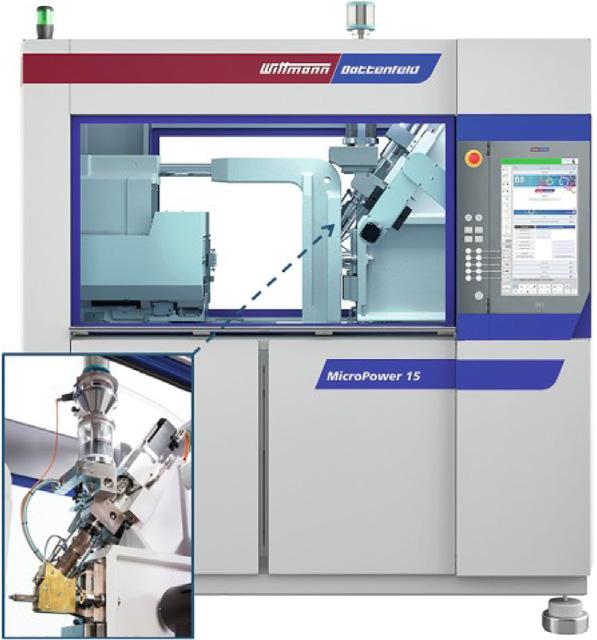
Figure1.7 Anappropriateexampleofamicroinjectionmoldingmachinedeveloped anddistributedbyWittmannBattenfeldGmbH,Austria.Thismachineisequipped withaspecialplungersystemforthereplicationofmicrocomponents.Asthe plungerdiameterscanbemuchsmallerthanthoseofthescrews,eventhelowest shotvolumescanbemeasuredoutandinjectedprecisely.37,38
Kogyo(Japan),andSodickCo.Ltd.(Japan).Onesuchexampleisshown in Fig.1.7
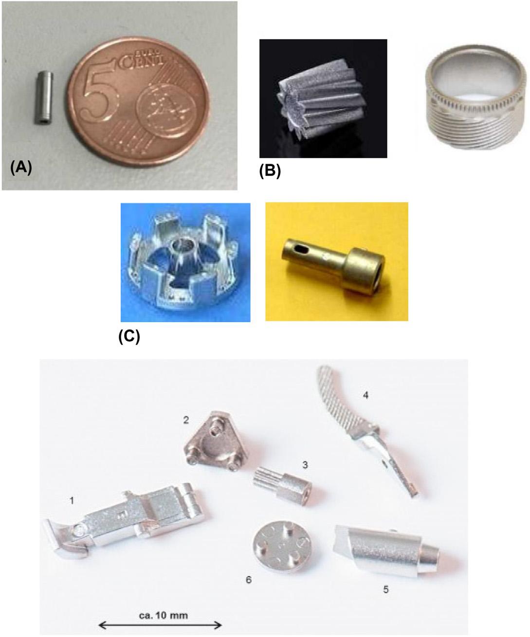
ItisbeyondthescopeofthischaptertodescribethemicroMIMprocessinfulldetail.Interestedreadersareadvisedtorefertothereference37 andthecitedliteraturethereof.ExamplesofindustrialmicroMIMproductsalreadyonthemarketaregivenin Fig.1.8
Two-materialMIMormorecommonlyknownastwo-colorortwocomponentMIM(2C-MIM)isanotherextensionoftheconventional MIMprocessthathasseensignificantinterestinrecenttimes.Theearly investigationsinto2C-MIMwerecarriedoutbyPischangetal.40 Since
Figure1.8 AselectionofvariousmicroMIMsamples:(A)theworld’ssmallestcheck valve,lessthan0.2mminthickness;(B)microgears;(C)soft-magneticmaterial;(1) plug-inelementforglassfiberconnectors,7%NiFe;(2,3)componentsfordentalelectroengines,17-4PH;(4)clampingjawformedicalinstruments,17-4PH;(5)arresting boltforammunition,316L;(6)gearwheelcarrierformicroelectroengines,AlSi4140. Pictures(A C)courtesyTaiseiKogyoCo.Ltd.https://www.taisei-kogyo.com/en/facility/ enmicromimtech.php.,whilepictures(1 6)aretakenfromPiotter,V.,15 MicroMetal InjectionMolding(MicroMIM).In HandbookofMetalInjectionMolding,2nded., Heaney,D.F.,Ed.;WoodheadPublishing,2019,pp333 360.
then,theconceptandevaluationof2C-MIMhavebeenappliedtomany materialsystemswithavarietyofpotentialapplications.41
LikeinMIM,2C-MIMstartswiththepreparationandrheological characterizationoffeedstock,followedbyinjectionmoldingtoforma greenpart.Moldingofthepartscanbeaccomplishedeitherviaovermoldingorcoinjectionmolding.Theovermoldingistypicallyamanual
Figure1.9 Cross-sectionaldifferencebetweenthetwo2C-MIMvariants.42
process.Inthisvariant,thefirstonecomponentismolded;oncethecomponentiscooleddowntoroomtemperature,itisthentransferredto anothermoldwhereovermoldingiscarriedouttoachievethedesired shape.Theresultingmoldedpartiscomposedoftwodifferentmaterials. Afterthermaldebindingandsintering,asingle,integratedcomponent results.Thisprocessisbestachievedusingatwin-barrelinjectionmolding units.Incoinjectionmolding,afunctionallygradedstructureisproduced usingdistinctflowbehaviorofthematerialsviathesamerunnersystem. Theresultingcomponenthasacoreandskinoftwodifferentmaterials. Fig.1.9 schematicallyillustratesthecross-sectionaldifferencebetween overmoldingandcoinjectionmolding.
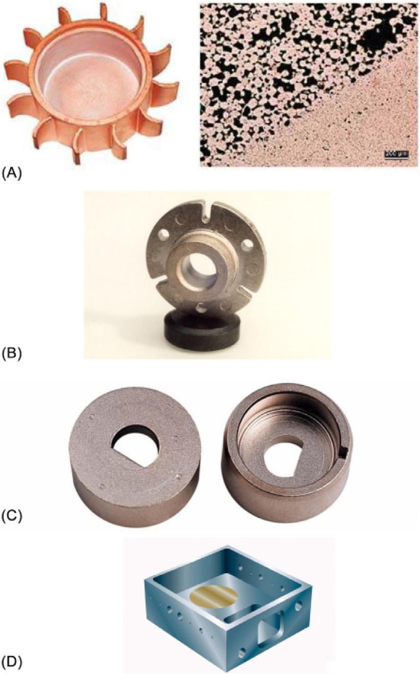
Successfulprototypesmadeusing2C-MIMtechnologyareshownin Fig.1.10
CompaniessuchasTaiseiKogyoCo.Ltd.areleadingthewayin researchanddevelopmentofMIMtechnology.ApartfrommicroMIM, thecompanyhassuccessfullybeenabletoproducehollow,complexcomponentsorcomplexpartswithundercuts.Thismethodisillustratedin Fig.1.11
1.3.3Currentstatus
AccordingtoMatthewBulger,MIMisnowrecognizedasoneofthetop tenadvancedmanufacturingtechnologies,rankingonlysecondtoadditive manufacturing.20 MIMhascontinuedtogaininterestinrecentyears.In particular,overthepast7years,ithasachievedexceptionalsuccess.This isespeciallyattributedtothesignificantgrowthintheelectronicsindustry inChina20 (Fig.1.12).
AccordingtoaleadingMIMindustryconsultantDr.Y.H.Chiou, widelyknownasDr.Q,theabilityoftheMIMindustrytomanufacture highvolumesofsmall,lightpartscoincideswiththeconsumer’sdesireto carryandwearevermoreelectronicdevices.Thecompetitivenessof MIMkeepspacewiththedemandsofthesmartphoneindustry,andthe technologycontinuestothrive.Whenwelookateachgenerationof
Figure1.10 Afewpicturesandschematicdiagramsofafewprototypesexplored via2C-MIM,(A)copper-basedheatsinkwithporouschannelsactingasheatpipes, (B)and(C)automotivesensorholders,(D)housingforahermeticallysealedelectronicpackagewithanembeddedheatsink.Thesepicturesandtheirdescriptionare takenfromRef.[41]Forreadersseekingdetailedinformationregarding2C-MIM, pleaseseeRef.[38]andthecitedliteraturethereof.
mobilenetworksandtelecommunicationtechnologyupgrades,acorrespondingproportionalgrowthcanbeseeninMIM’sglobalgrossproduct forthissector43 (Fig.1.13).
Theadventofnewhigh-speedcommunicationtechnologyinthe5G erameansthatMIMisalsofacinganimportanteraof “hidden” needsin thewider5Gecosystem.Physically,itisdifficulttosolvethechallenges of5Gsimplyusingconventionaltechnology,becauseofthedemandfor heatdissipation,electromagneticcompatibility,currentconduction,and