Prince of Fire (Warriors of the Fianna Book 2) Sophia Nye
https://ebookmass.com/product/prince-of-fire-warriors-of-the-fiannabook-2-sophia-nye/
ebookmass.com
Edited by
Abdelkhalak El Hami
Philippe Pougnet
First edition published 2015 in Great Britain and the United States by ISTE Press Ltd and Elsevier Ltd
© ISTE Press Ltd 2015.
This edition published 2020 in Great Britain and the United States by ISTE Press Ltd and Elsevier Ltd
Apart from any fair dealing for the purposes of research or private study, or criticism or review, as permitted under the Copyright, Designs and Patents Act 1988, this publication may only be reproduced, stored or transmitted, in any form or by any means, with the prior permission in writing of the publishers, or in the case of reprographic reproduction in accordance with the terms and licenses issued by the CLA. Enquiries concerning reproduction outside these terms should be sent to the publishers at the undermentioned address:
ISTE Press Ltd
27-37 St George’s Road
Elsevier Ltd
The Boulevard, Langford Lane London SW19 4EU Kidlington, Oxford, OX5 1GB UK UK
www.iste.co.uk
Notices
www.elsevier.com
Knowledge and best practice in this field are constantly changing. As new research and experience broaden our understanding, changes in research methods, professional practices, or medical treatment may become necessary.
Practitioners and researchers must always rely on their own experience and knowledge in evaluating and using any information, methods, compounds, or experiments described herein. In using such information or methods they should be mindful of their own safety and the safety of others, including parties for whom they have a professional responsibility.
To the fullest extent of the law, neither the Publisher nor the authors, contributors, or editors, assume any liability for any injury and/or damage to persons or property as a matter of products liability, negligence or otherwise, or from any use or operation of any methods, products, instructions, or ideas contained in the material herein.
MATLAB® is a trademark of The MathWorks, Inc. and is used with permission. The MathWorks does not warrant the accuracy of the text or exercises in this book. This book’s use or discussion of MATLAB® software or related products does not constitute endorsement or sponsorship by The MathWorks of a particular pedagogical approach or particular use of the MATLAB® software.
For information on all our publications visit our website at http://store.elsevier.com/
© ISTE Press Ltd 2020
The rights of Abdelkhalak El Hami and Philippe Pougnet to be identified as the authors of this work have been asserted by them in accordance with the Copyright, Designs and Patents Act 1988.
British Library Cataloguing-in-Publication Data
A CIP record for this book is available from the British Library Library of Congress Cataloging in Publication Data
A catalog record for this book is available from the Library of Congress ISBN 978-1-78548-190-1
Printed and bound in the UK and US
Preface
Electronics are increasingly used in controlled and embedded mechanical systems. This leads to new mechatronics devices which are lighter, smaller and use less energy. However, this mechatronics approach which enables technological breakthroughs must take into account sometimes contradictory constraints such as lead-time to market and cost savings. Consequently, implementing a mechatronic device and mastering its reliability are not always entirely synchronized processes. For instance, this is the case of systems that function in harsh environments or in operating conditions which cause failures. Indeed, when the root causes of such defects are not understood, they can be more difficult to control. This book answers to these problems. It is intended for stakeholders in the field of embedded mechatronics so that they can reduce the industrial and financial risks linked to operational defects. This book presents a method to develop mechatronics products where reliability is an ongoing process starting in the initial product design stages. It is based on understanding the failure mechanisms in mechatronic systems. These failure mechanism are modeled to simulate the consequences, and experiments are carried out to optimize the numerical approach. The simulation helps to reduce the time required to anticipate the causes of these failures. The experiments help to refine the models which represent the systems studied.
This book is the result of collaborative research activities between private (big, intermediate and small businesses) and public sector agents (universities and engineering schools). The orientations of these research works were initiated by the Mechatronics Strategical Branch of the Mov’eo competitive cluster (Domaine d’Action Stratégique) to meet the need to have reliable mechatronics systems.
This book is directed at engineers and researchers working in the mechatronics industry as well as at Masters or PhD students aiming to specialize in experimental investigations, in experimental characterization of physical or chemical stresses, in failure analysis, and in failure mechanism modeling to simulate the consequences of causes of failure and wanting to use statistics to assess reliability. These subjects match the needs of the mechatronics industry.
It is organized into two volumes. Volume 1 presents the statistical approach for optimizing designs for reliability and the experimental approach for characterizing the evolution of mechatronic systems in operation. Volume 2 looks at trials and multi-physical modeling of defects which show weaknesses in design, and the creation of metamodels for optimizing designs.
Chapter 1 of this volume discusses a methodology for carrying out highly accelerated life tests (HALT) in a humid environment. The principle is to subject the device under test (DUT) to humid air. The ability of the HALT chamber to vary the temperature while applying vibrations enhances the penetration of humidity into the DUT, especially in the case of a failure of water-tightness. Depending on the temperature, this humidity may be in the form of steam or frost on electronic circuit boards and highlight the weaknesses in the assembly or interconnections and failure of water-tightness. Electromagnetic disturbances are also sources of failures. Weaknesses in the design of circuits and components are checked by ensuring the electromagnetic compatibility (EMC) through a characterization of the disturbances produced and the emissions before and after the highly accelerated tests.
Preface xv
Chapter 2 describes how to conduct life tests on high-frequency power transistors under operational conditions. The originality of this test is to follow the performance of the component in an automated way over thousands of hours while applying electric and thermal stresses. The test examines high power components in pulsing mode and tracks deviations by in situ static and dynamic electric characterizations. The life cycle results obtained for high-power laterally diffused metal oxide semiconductor (LDMOS) transistors are presented.
Chapter 3 presents the methodology for analyzing failures of mechatronic systems. The advantages and disadvantages of different techniques of opening the resin and ceramic casings are described as well as the precautions to be used to preserve the operational and structural integrity of the component. The technique of detecting and locating defects by photon emission microscopy (PEM) is combined with the optical-beam-induced resistance change (OBIRCH) technique to guide the analysis and determine the cause of the failure. Four case studies of failure analysis are presented: a defective IGBT-power component after the test, a metal oxide semiconductor field effect transistor (MOSFET) damaged by the electrical overvoltage stress test, a GaN technology transistor damaged during reliability testing and a LDMOS component damaged during life test. The results of these analyses are presented, helping to identify the cause of the defects (X-ray analysis, electrical analysis, optical microscopy analysis, thermal analysis, photon emission analysis, transmission electron microscopy analysis).
Chapter 4 examines the phenomenon of thermal transfer due to the heat dissipation in a power module and its effects. During the assembly of a mechatronic module, void defects may appear in the interconnection material (ICM). By trapping thermal energy, these defects are potential sources of failure in the module. The goal of this study is to determine the effect of such imperfections on reliability by using the maximum temperature parameters of the chip and the thermo-mechanical constraints at the interfaces as indicators.
Chapter 5 describes modeling techniques based on the finite element methods to study the effect on electronic circuit boards of temperature cycling, vibrations and electric loads. The electric, thermal and mechanical behavior of a mechatronic structure is presented. Details of two types of coupling of physical phenomena are given. The first is strong coupling: it uses finite elements with all degrees of freedom necessary for an electro-thermo-mechanical study. The second is weak coupling: it consists of decoupling the three physical phenomena, with a sequential calculation. This method is applied to the electronic circuit board of an engine control unit and to a radar power amplifier. Understanding the mechanical behavior of electric circuit boards requires the modeling of several physical phenomena. A multi-physical model is presented which takes into account the interdependencies and interactions between various physical phenomena: electric, thermal and vibratory.
Chapter 6 presents a number of methods to optimize the reliability of mechatronic systems. The principle is to combine a finite element numerical model describing the physical response of a mechatronic system with a stochastic model. The results of numerical modeling make it possible to build a meta-model using the response surface. By using this meta-model, the level of control factors is adjusted, the sensitivity of the mechatronic system to sources of variability is reduced (noise factors) and the response of the system is adjusted to meet the reliability objective.
Chapter 7 presents a probabilistic approach of aging and fatigue phenomena in solder interconnects caused by temperature cycles. This approach is applied to study the effect of thermomechanical stresses on the reliability of a solder joint in an embedded mechatronic system. It takes into account uncertainties resulting from the random nature of temperature fluctuations, the geometric dimensions of an electronic assembly and the properties of materials. The volume of the solder interconnect material is optimized and the solder joint strength relative to the thermomechanical stresses caused by thermal loads is improved.
Preface xvii
Chapter 8 presents a study of the reliability of a radiofrequency power amplifier for RADAR applications using Gallium-Nitride Highelectron-mobility transistors (HEMT) of A1GaN/GaN technology. In order to determine the parameters which impact the reliability of this power amplifier, electric characterizations, aging tests and physical analysis are combined. The results show that temperature is the most significant parameter determining aging and that the gate contact of the HEMT is the most sensitive element. A model of the HEMT component integrating the effect of aging is presented.
Chapter 9 presents a method for predicting the reliability of solder joints in Tape-Chip-Scale Packages (T-CSP) that take into account uncertainties in the properties of materials. This approach, which is based on metamodeling techniques, combines FEM simulation, metamodels and Monte Carlo simulation (MCS). The approach consists of building and validating a metamodel. Then, this metamodel is used to perform Monte Carlo simulations. This probabilistic approach is efficient and accurate enough to evaluate and improve the reliability of T-CSPs.
The authors would like to thank DGCIS, CR Haute-Normandie, CG 95, CG91, CG78, CRBN, CRIF, CA Cergy Pontoise, MOV’EO and NAE for supporting the project AUDACE.
Abdelkhalak EL HAMI
Philippe POUGNET August 2019
Highly Accelerated Testing
“Highly accelerated life testing” (HALT) was invented in the USA in the 1980s. In Europe, this method is called both HALT and “highly accelerated testing” (HAT). HALT and HAT are experimental tests which reveal design weaknesses of electronic devices by subjecting them to vibration, temperature and ramp temperature stresses. These tests are best used at technology readiness level 4 or 5 in product development as specified in the international norm ISO 16290. HAT tests take place in a dry environment. Humidity is an important factor of stress which may lead to failures in embedded mechatronic systems [ZVE 13]. This chapter will present an HAT method in a humid environment. The principle is to apply humid air to the device under test (DUT). The HAT chamber makes it possible to vary the temperature rapidly at the same time as vibrations resulting in the humidity penetrating the DUT, especially when the sealing is defective. Depending on the temperature, this humidity takes the form of vapor or ice on the electronic boards and exposes the weaknesses of assemblies, interconnects or tightness defects. The design defects of the electromagnetic compatibility (EMC) circuits are revealed by performing conducted and emitted radiation tests before and after HAT.
1.1. Introduction
Recently, there has been a huge increase in mechatronic product developments in spite of the trend to reduce the time to market lead time. Mechatronic products offer more functions and are expected not to fail during the product life time. In order to meet these market
Chapter written by Philippe POUGNET, Pierre Richard DAHOO and Jean-Loup ALVAREZ.
requirements, it is necessary to identify the maximum number of design flaws, reduce test durations significantly and apply and validate corrective actions.
HAT is an experimental approach based on the vibration and thermal stresses which reveal design and technology weaknesses, and operational and destruct limits [HOB 05, BNA 05, MCL 09, IEC 13]. HAT is not used to qualify products but rather to optimize design. These tests are best used at technology readiness level 4 or 5 in product development as specified in the international norm ISO 16290.2013 [ISO 13]. The prototypes are tested at the beginning of product development to reveal defects or flaws when it is still easy and not expensive to modify the design. Correcting these flaws improves product strength to operational and environmental loads and optimizes the design, reducing potential failures in service. As validation testing time is shortened, development cost is reduced, which makes the product more competitive. The reduction in the rate of returned parts during the warranty period improves brand image.
Temperature, vibrations and humidity are sources of stress for mechatronic systems [ZVE 13]. These stresses act separately or interact, leading to complex physical chemical electrical mechanisms of degradation or failure. To improve design, these factors need to be analyzed and effective counter measures taken. The principle of HAT is to reproduce these external causes of failure in extreme conditions (maximum stress, reduced test time) in order to understand the physical or chemical causes of failure and assess their respective impact. In this approach, stress is increased step by step to a far higher degree than the levels which are specified in the contract that defines operational functioning. Mechatronic systems are often equipped with protection that prevents these extreme conditions. In this case, this protection should be disabled so that intrinsic functioning limits can be reached.
Discovering the design weaknesses requires a test that can detect whether the mechatronic system has failed to function either partially or totally. At each step, this test characterizes the ability of the system to perform its expected functions. It also measures the critical parameters and diagnoses potential failures. The stresses applied (temperature, vibration) to the areas at risk in the DUT are measured and recorded.
The HALT and HAT approaches are designed to find the functioning and destruction limits in a dry atmosphere. The “Super HAT” method goes a step further since it includes humidity. The DUT is subjected to increased humidity levels and this combined with stresses creating vibrations and rapid temperature ramps reveals significant additional weaknesses. These defects would not have been detected otherwise and would have led to failures in operation. It is possible to acquire equipment to test a combination of two of these three factors (e.g. vibration and temperature or temperature and humidity). However, no other highly accelerated test equipment exists that combines all three (vibration, temperature and humidity) except for the Super HAT.
1.2. Load characteristics of the Super HAT equipment
Combining a thermal, vibration and humid environment, the Super HAT system produces highly accelerated loads.
The temperature range is 100 to 200°C and the maximum ramp used to increase or decrease the temperature is 60°C/min. Random vibrations have 6 degrees of freedom (3 degrees for translation movement and 3 degrees for rotating). The root mean square (RMS) vibration amplitude can be varied from 0 to 50 Grms. The frequency bandwidth of the applied vibrations is 10–10,000 Hz. Maximum relative humidity is 95% at 95°C.
The Super HAT system can handle devices up to 60 cm × 60 cm with a height of 40 cm and a maximum weight of 50 kg. DUTs are attached to the vibration table by specifically designed fixtures. The pilot system can be used to establish test profiles.
1.3. Description of the Super HAT system
1.3.1. System configuration
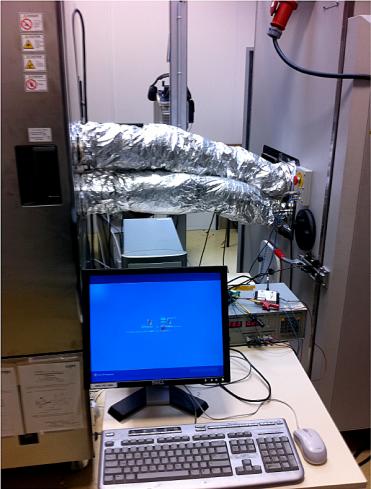
A HAT chamber and a large volume humidity chamber are used to reproduce the stresses caused by humidity, vibrations and temperature. The chambers are connected by two ducts. To avoid the condensation of humid air, the two ducts are thermally insulated (Figure 1.2). A four-way electrovalve regulates the flow of moisture on the DUT. A fan helps humid air flow between the two chambers.
Figure 1.1. Schematics of the Super HAT system
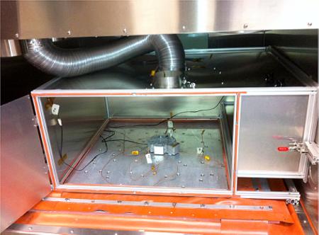
The DUT is placed in a sealed casing (Figure 1.3) which limits the volume of humid air to ensure an initial humidity ratio of 85% and maintain a humidity rate between 65% and 85% during the test cycles. This insulated casing is fixed to the side walls of the HAT chamber. Airtightness is achieved by using a flexible material which allows random vibrations to be applied in a humid atmosphere. An additional generator is available to maintain the humidity ratio of the test profiles especially when the cycles are repeating.
In order to control any rapid increase and decrease in temperature, the casing is connected to the dry nitrogen supply of the HAT chamber. Valves are used to control the dry nitrogen flow.
Figure 1.2. Thermally insulated connection between the two chambers
Figure 1.3. Airtight casing to reduce the volume of moisture
1.3.2. Control and monitoring system
The control system initiates and controls the functioning of the two chambers. It synchronizes the optimal conditions for the transfer of humid air from the humidity chamber to the casing in the HAT chamber. It records the progressive change of physical test parameters (temperature, humidity and vibration).
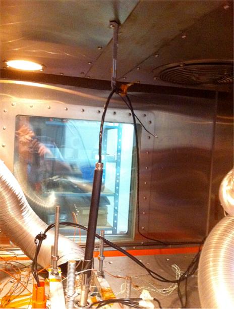
Low thermal inertia thermocouples, low mass accelerometers and a precise relative humidity sensor (Figure 1.4) are positioned in the two chambers and on the DUT to measure the characteristics of the applied loads (temperature, vibration and humidity).
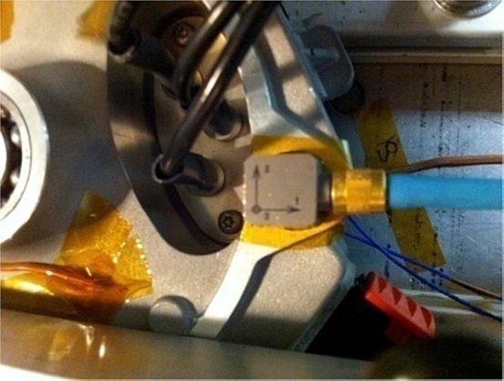
The monitoring system allows us not only to record the signals given by the temperature, vibration and humidity sensors positioned in the chambers, but also the signals from the sensors positioned on the critical elements on each DUT (Figure 1.5). Thus, the stresses applied on the DUT are monitored directly. A multichannel data acquisition system records the effective applied stress levels measured by the sensors. The control system detects the resulting failures and malfunction levels that are correlated to the data.
Figure 1.4. Relative humidity sensor in the casing
Figure 1.5. Three axis accelerometer and thermocouple positioned on the DUT
1.3.3. Test profiles
Different test profiles can be set by the control system. An example of such a cycling test profile is given in Figure 1.6.
Figure 1.6. Applied test profile: a) temperature setting (°C), b) DUT temperature (°C) and c) relative humidity (%). For a color version of the figure, see www.iste.co.uk/elhami/embedded2b.zip
The initial DUT temperature is fixed at room temperature in the casing. This temperature is then decreased to 20°C at a rate of 50°C/min by blowing cold dry nitrogen gas inside. After a 10 min dwell time at this temperature, the DUT is heated to 90°C (setting temperature) at a rate of 50°C/min by this time blowing hot dry nitrogen gas inside. Once the temperature has stabilized, the valves of the nitrogen gas ducts are closed. Moisture is introduced from the second apparatus by activating the four-way valve. Relative humidity reaches a peak value of 80% to finally stabilize at 70%. The moisture dwell time is approximately 8 min. Then, the four-way electrovalve is closed and the electrovalves of the nitrogen gas ducts are opened to obtain condensation of humidity on the electronics. Cold nitrogen is then blown on the DUT to reduce its temperature over more than 3–5 min down to 40°C. The electronics are covered by ice for 10 min. Then, the DUT is heated to 90°C at a rate of 50°C/min by blowing hot dry nitrogen gas. This turbulent hot nitrogen flow decreases the humidity level. After a 7 min dwell time, moisture is reintroduced and a new cycle begins.
This test profile is designed to precipitate defects due to humidity. Moisture can seep into the DUT housing due to defects in the sealing joints or connectors, or through the microporous membrane which balances the pressure inside and out of the DUT and which is permeable to water vapor because of its function. The climate inside the DUT results from leakages of the moisture absorbed by the polymer materials used in assembly or potting or from the temperature cycles of the electronics. The preceding test profile is designed to increase the defects due to humidity inside the DUT casing because it is colder and therefore at a lower pressure than the surrounding atmosphere. Reducing the temperature to a very low 40°C ensures that moisture is condensed on the electronic components and on the walls of the casing. At a high temperature, this condensed moisture melts and water interacts with potting and sealing materials to reveal their weaknesses.
1.3.4. Utility operating conditions
The Super HAT system functions if the following conditions [HOB 05] are met:
– a liquid nitrogen tank equipped with a heating element to produce gas, vents and manual and automatic safety valves;
– trucks carrying liquid nitrogen must be able to access an outside refueling line equipped with a valve;
– a vacuum-jacketed line to the HAT chamber and a nitrogen gas line;
– specific liquid nitrogen pipes (equipped with a manual safety valve), nitrogen gas pipes (equipped with a safety valve and pressure regulator), thermally insulated pipes to extract the nitrogen gas out of the building, a degassing valve between the safety valve and the HAT chamber bayonet and the evacuation pipe for the degassing pot of the liquid nitrogen line;
– a set of sensors and alarm systems warning if nitrogen leaks may cause a risk of lack of oxygen for the personnel;
– an automatic command system for closing down the liquid and nitrogen gas valves;
– an oil-free air compressor equipped with filters and a storage tank;
– an electric power supply line (3 phases 400 V, 80 A).
Standard performance includes:
– a 5,000 l tank for liquid nitrogen;
– a non-continuous liquid nitrogen flow rate of 50 l/min at 3.45 bars;
– a nitrogen gas flow rate of 8,488 l/h at 1 bar (maximum pressure 4.8 bars, nominal pressure 0.3–0.5 bar);
– a compressed air flow rate of 2.27 m3/min at 5.5 bar (this air should be dry dew point between 1.6 and 3.9°C filtered at 1–5 µm, oil free, and a 500 l minimum storage tank).
The moisture chamber requires a 3 phase 400 V 32 A power supply and 10–30 l of distilled water per test.
1.4. Application
The Super HAT tests consist of applying step stresses according to the HAT protocol before introducing moisture and experimental combinations of temperature and humidity and variations in temperature, random vibrations and humidity.
1.4.1. Device under test
The DUT is a device that controls the compressor of an electric automotive air conditioner (Figure 1.7). Its main functions are to regulate the inside temperature and to control the battery temperature when it is charged at low or high speed. This device must function without failure for a 25,000 h lifetime. The temperature operation specification that needs to be met is from 10 to 100°C. Nominal operation temperature is 85°C. The torque supplying the heat-retaining fluid compressor varies from 1.5 to 5 Nm.
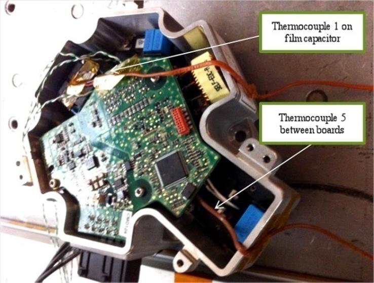
Figure 1.7. The DUT equipped with two thermocouples
The DUT is composed of two electronic boards (a power board and a control board) which are enclosed in an aluminum alloy casing. The power board is coated in resin and is attached to the casing. The casing contains a 350 V High Voltage (HV) direct current connector (positive and negative terminals are labeled HV+ and HV–), a 13.5 V Low Voltage (LV) connector (positive and negative terminals are labeled LV+ and LV–), a Controlled Area Network (CAN) bus and a ball bearing. The casing is designed to be waterproof. To avoid stresses on the casing lid and on the sealing joints, a microporous membrane has been added. This membrane is waterproofed against water but not against steam. In operation, the bottom of the casing is in contact with the cooling fluid which can lead to water condensing on the electronics.
The following prototypes are tested:
N°114 (uncoated power board equipped with thermocouples and without lid);
N°112 (resin-coated power board, sealed lid and microporous membrane);
N°120 (uncoated power board, equipped with thermocouples, sealed lid and microporous membrane).
1.4.2. Mounting of the DUT on the HAT vibration table
The HAT vibration table is set to vibrate by repetitive shocks from numerous pneumatic actuators which are positioned under the table in specific places. The spectral content is multiaxial and random on a wide frequency bandwidth (from 10 Hz to 10 kHz). However, to avoid damping, the DUT should be attached with flexible fixtures.
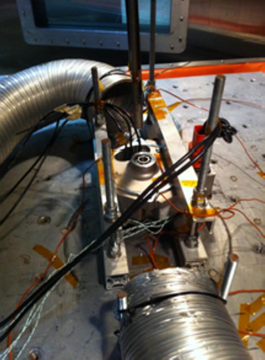
The DUT is thus mounted on the vibration table with light alloy fixtures and with threaded rods blocked by nuts and locknuts (Figure 1.8).
1.4.3. Testing for operating temperature limits
To discover the operating temperature limits, it is recommended to remove the protective casing lid to optimize thermal exchanges between the electronics and the nitrogen gas flow. The temperature levels and the thermal ramps activate defects.
Prototype N°114 is tested for operating limits. The casing is open and power components are not coated in resin. The test protocol is as follows: at each temperature step change, once the DUT temperature is stabilized, power cycles are activated and functioning is checked.
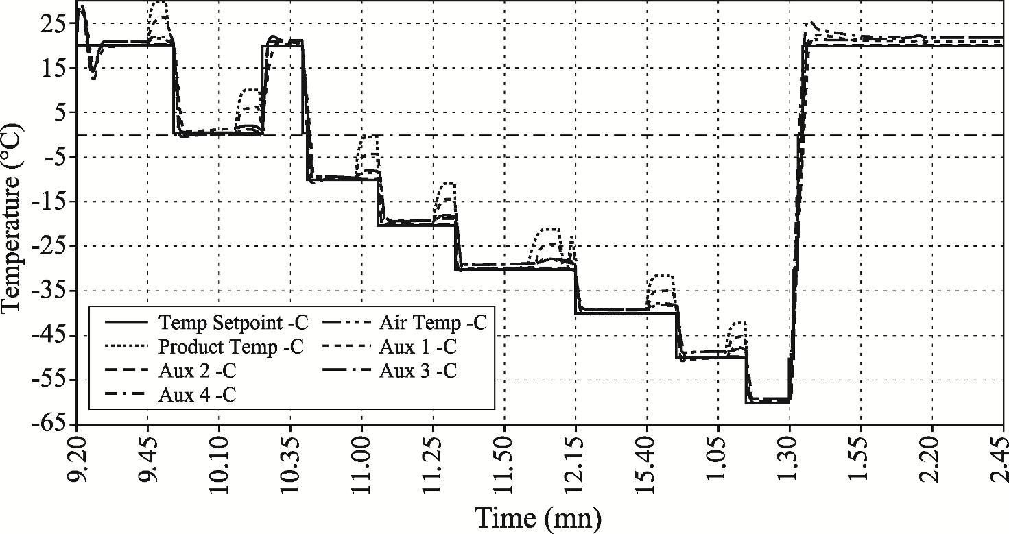
1.4.3.1. Testing for low-temperature operating limit
The DUT functioning is checked at a temperature of 20°C. The temperature is lowered to 0°C and the functioning is rechecked. The temperature is lowered progressively to 20°C at a time. Dwell time at each step is 15 min. Figure 1.9 shows the evolution of the DUT temperature over time.
Figure 1.8. Mounting of the DUT and the nitrogen pipes
DUT
3/8 threaded rod
Top Aluminum bar
Set of nutand locknut tightenedat 10 Nm
Bottom Aluminumbar withwasher inside
1.9. Operating limit at low temperature: DST temperature (°C) and testing time (min)
When power cycles are activated, the temperature of the power board increases from 10 to 35°C depending on the location of the sensors. No defects are revealed until 60°C when testing is stopped.
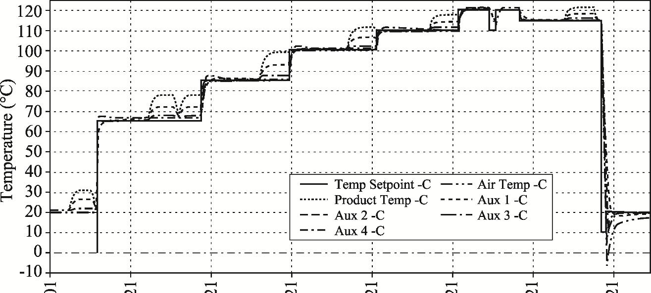
1.4.3.2. Testing for high-temperature operating limit
The DST functioning is checked at 20°C and again at 65°C. The step dwell time is 15 min. The DUT is checked again at 100°C. The temperature is then increased by 10°C steps. No defects are revealed and the test is stopped at 120°C.
1.10. Operational limit at high temperature: DUT temperature (°C) versus testing time (min)
Figure
Figure
1.4.4. Testing for weaknesses due to rapid temperature changes
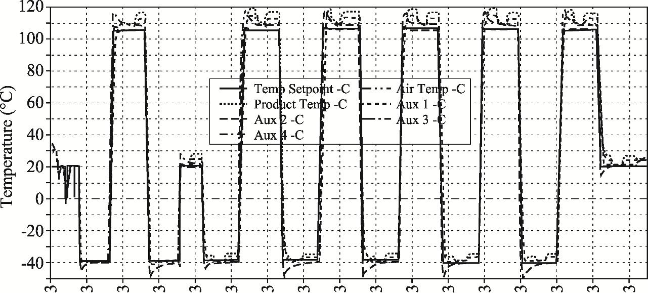
Prototype N°114 undergoes five rapid temperature cycles. The ramp rate is 60°C/min. The thermal cycle extremes are 40 and 105°C (Figure 1.11).
Figure 1.11. Testing for weaknesses due to rapid thermal changes: DST and setup temperature (°C) versus time (min)
The DUT functioning is checked after each cycle at the end of the hot temperature dwell time (105°C). Dwell time is 25 min. No defects are detected.
1.4.5. Testing for random vibration limits
Prototype N°112 is tested for vibration limits. Its power board is coated in resin to limit movements and reduce deformations of passive power components caused by vibrations. One objective of this test is to check that this resin protects against vibrations.
The vibrations created by the pneumatic actuators are random multiaxial vibrations with a large frequency bandwidth. However, they are not controlled. The only control data available are the RMS amplitude of the signal from the acceleration under the vibration table. In order to obtain the spectral power density applied on the DUT, acceleration sensors are placed precisely where potential weaknesses
Accelerated Testing 15
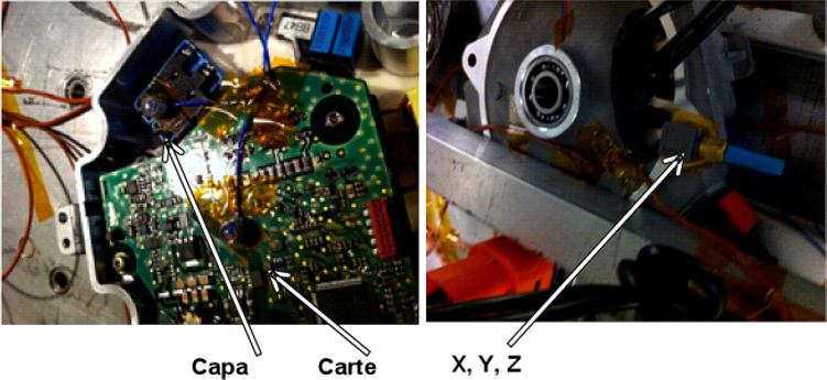
have been identified. The location of the accelerometers is shown in Figure 1.12. Monoaxial sensors are positioned on the power capacitor of the power board and at the middle of the control board. A triaxial accelerometer is placed on the casing.
Figure 1.12. Location of accelerometers on control board (carte), power capacitor (capa) and casing
Figure 1.13 displays the RMS acceleration measured by the accelerometers of the DUT versus the RMS acceleration obtained from the vibration table sensor. The RMS acceleration of the control board and power board does not vary linearly with the RMS acceleration from the table sensor that is used at a set point. It is thus important to position accelerometers on previously identified potential defects in order to have precise data on the applied power spectral density.
RMS accelerationfromDUT sensors (Grms)
RMS accelerationfromtable sensor(Grms)
Figure 1.13. Root mean square acceleration (Grms) of DUT sensors versus root mean square acceleration from table sensor (Grms). For a color version of the figure, see www.iste.co.uk/elhami/embedded2b.zip
Figure 1.14 displays the RMS acceleration from the DUT sensors versus frequency. These data are necessary to know the power spectral density that is applied locally on the DUT.
Figure 1.14. Power spectral density (Grms2/ Hz) obtained from the DUT acceleration sensors (Y, X, Z), (CAPA) and (CARTE) versus frequency (Hz). For a color version of the figure, see www.iste.co.uk/elhami/embedded2b.zip
1.4.6. Testing for limits due to the combined stresses of rapid temperature changes and random vibrations
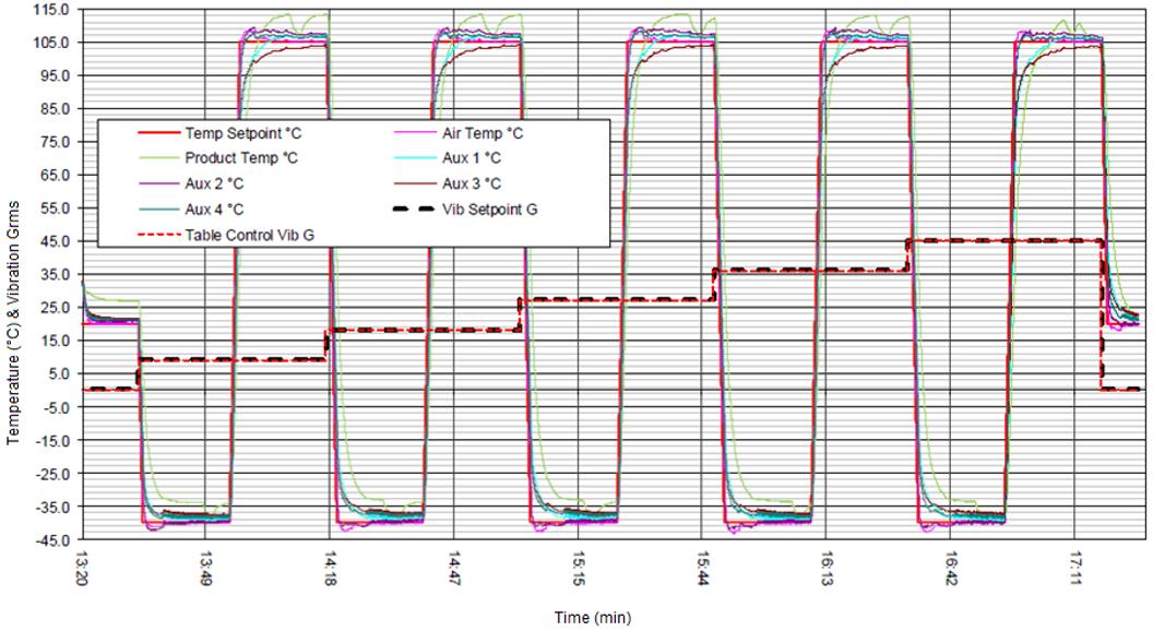
Prototype N°112 is tested simultaneously for rapid thermal changes (from 40 to 105°C) and random vibrations. The thermal ramp is 60°C/min. The random vibration level is increased step by step. These steps (9, 18, 27, 35 and 45 Grms) are shown in Figure 1.15.
Several defects are revealed at the last vibration step (45 Grms) and at the temperature of 105°C:
– failure of one high-side insulated gate bipolar transistor (IGBT) transistor of the power board (suspected design flaw);
– disconnection of the interlock loop (this wire was not mounted using standard production line procedure) assembly;
– disconnection of two capacitances (these were not properly coated by resin, an assembly process defect); – the screw connecting the DUT to the earth was completely removed.
Figure 1.15. Testing for limits due to combined rapid thermal changes and vibrations: DUT temperature (°C) and RMS acceleration versus time (min). For a color version of the figure, see www.iste.co.uk/elhami/embedded2b.zip
1.4.7. Testing for limits due to the combined stresses of rapid temperature changes, random vibrations and moisture
Prototype N°120 is protected against potential external environment stresses by a metallic casing and sealing joints. Air pressure inside this prototype is regulated by a microporous membrane that balances external and internal pressures when the power board is activated and heats up.
To test the limits for moisture, the DUT is subjected to combined thermal and humidity cycles. The temperature cycle varies from 40 to 95°C. The ramp rate is 60°C/min. The temperature dwell time is 15 min. The DUT is exposed to 80% moisture for 6 min (Figure 1.16). No defects are detected.