This edition published 2019 in Great Britain and the United States by ISTE Press Ltd and Elsevier Ltd
Apart from any fair dealing for the purposes of research or private study, or criticism or review, as permitted under the Copyright, Designs and Patents Act 1988, this publication may only be reproduced, stored or transmitted, in any form or by any means, with the prior permission in writing of the publishers, or in the case of reprographic reproduction in accordance with the terms and licenses issued by the CLA. Enquiries concerning reproduction outside these terms should be sent to the publishers at the undermentioned address:
ISTE Press Ltd
27-37 St George’s Road
Elsevier Ltd
The Boulevard, Langford Lane London SW19 4EU Kidlington, Oxford, OX5 1GB UK UK
www.iste.co.uk
Notices
www.elsevier.com
Knowledge and best practice in this field are constantly changing. As new research and experience broaden our understanding, changes in research methods, professional practices, or medical treatment may become necessary.
Practitioners and researchers must always rely on their own experience and knowledge in evaluating and using any information, methods, compounds, or experiments described herein. In using such information or methods they should be mindful of their own safety and the safety of others, including parties for whom they have a professional responsibility.
To the fullest extent of the law, neither the Publisher nor the authors, contributors, or editors, assume any liability for any injury and/or damage to persons or property as a matter of products liability, negligence or otherwise, or from any use or operation of any methods, products, instructions, or ideas contained in the material herein.
MATLAB® is a trademark of The MathWorks, Inc. and is used with permission. The MathWorks does not warrant the accuracy of the text or exercises in this book. This book’s use or discussion of MATLAB® software or related products does not constitute endorsement or sponsorship by The MathWorks of a particular pedagogical approach or particular use of the MATLAB® software.
For information on all our publications visit our website at http://store.elsevier.com/
The rights of Abdelkhalak El Hami and Philippe Pougnet to be identified as the authors of this work have been asserted by them in accordance with the Copyright, Designs and Patents Act 1988.
British Library Cataloguing-in-Publication Data
A CIP record for this book is available from the British Library Library of Congress Cataloging in Publication Data
A catalog record for this book is available from the Library of Congress ISBN 978-1-78548-189-5
Printed and bound in the UK and US
Preface
Electronics are increasingly used in controlled and embedded mechanical systems. This leads to new mechatronics devices that are lighter, smaller and use less energy. However, this mechatronics approach, which enables technological breakthroughs, must take into account sometimes contradictory constraints such as lead-time to market and cost savings. Consequently, implementing a mechatronic device and mastering its reliability are not always entirely synchronized processes. For instance, this is the case for systems that function in harsh environments or in operating conditions which cause failures. Indeed, when the root causes of such defects are not understood, they can be more difficult to control. This book attempts to respond to these problems. It is intended for stakeholders in the field of embedded mechatronics so that they can reduce the industrial and financial risks linked to operational defects. This book presents a method to develop mechatronics products where reliability is an ongoing process starting in the initial product design stages. It is based on understanding the failure mechanisms in mechatronic systems. These failure mechanisms are modeled to simulate the consequences and experiments are carried out to optimize the numerical approach. The simulation helps to reduce the time required to anticipate the causes of these failures. The experiments help to refine the models which represent the systems studied.
This book is the result of collaborative research activities between private (big, intermediate and small businesses) and public sector agents (universities and engineering schools). The orientations of this research were initiated by the Mechatronics Strategic Branch of the Mov’eo competitive cluster (Domaine d’Action Stratégique) to meet the need to have reliable mechatronic systems.
This book is aimed at engineers and researchers working in the mechatronics industry and Master’s or PhD students looking to specialize in experimental investigations, experimental characterization of physical or chemical stresses, failure analysis and failure mechanism modeling to simulate the consequences of causes of failure and who want to use statistics to assess reliability. These subjects match the needs of the mechatronics industry.
This book is divided into two volumes. This volume presents the statistical approach for optimizing designs for reliability and the experimental approach for characterizing the evolution of mechatronic systems in operation. Volume 2 [ELH 19] looks at trials and multi-physical modeling of defects which show weaknesses in design and the creation of meta-models for optimizing designs.
Chapter 1 describes the reliability-driven design methodology by building on a case study. The first step in this approach is to define the reliability targets, the risks of failure due to architectural innovations or new conditions of use and then to evaluate the predictive reliability of the electronics. The objectives of the following steps are to identify the components that may fail in the life profile conditions and determine the distribution of the stresses causing these failures. In order to understand the potential failure mechanisms, experimental characterizations of the effects of mechanical, thermal or electromagnetic stresses are carried out on a few prototypes and tests are designed to provoke failures. Consecutive failure analysis helps to develop failure mechanism models. However, these multi-physical models are based on approximations and uncertainties. They have to be validated before being used to simulate the failures in the conditions of the life profile. Using statistical approaches, the multi-physical failure models can take into account the variability of the loads of the life profile as well as the variability of the
Preface xiii
manufacturing process. The design is then optimized by adjusting the architecture parameters that improve reliability. Chapter 2 describes the Spectroscopic Ellipsometry (SE) method. This method is often used in microelectronics to study semiconductors, polymer-based protective coatings, metals, or other types of meta-materials. SE is applied here to study the effect of environmental stresses on the quality of surfaces and interfaces of sintered silver materials and polymers of a mechatronic power module. A study of the effect of temperature in dry and wet environments is presented and discussed in terms of optical properties. Chapter 3 describes an approach determining emissions radiated from microwave structures found in metallic cavities. This approach is based on near-field cartographies and on a model of the emissions radiated from the open structure by a network of dipoles.
Chapter 4 presents the experimental study of the static and dynamic deformations of the components and electronic equipment, using optical techniques of coherent light based on full-field methods. The applied interferometric and non-interferometric techniques lead to complementary results in terms of temporal and spatial resolution as well as measuring sensitivity. These results have been obtained by applying the techniques of Speckle Interferometry (SI) to temporal integration, Moiré Projection (MP) and Structured Light (SL) to study the phenomena related to the thermomechanical and vibratory behaviour of the embedded electronic devices. Chapter 5 describes a method of characterizing the robustness of switching transistors relative to overvoltage electrical stresses. In this approach the phenomena of electrostatic discharge (ESD) are reproduced. Chapter 6 focuses on the study of the reliability and the robustness of radiofrequency power transistors (RF) used in power amplifier electronic boards (HPA: High Power Amplifier). These transistors are the base elements of the (Tx) transmission modules for radar applications. The effects of radiated electromagnetic waves, RF signals and thermal loads on Gallium Nitride (GaN) RF transistors are studied.
Chapter 7 presents a method for measuring temperature and micro-displacement on high frequency components used in telecommunications and radars. The simultaneity of the measurements of the temperature and expansion parameters represents the originality of this method. This approach makes it possible to calculate the thermal resistance of an electronic component and study how this resistance changes during the life of the component. Chapter 8 presents the FIDES predictive reliability handbook. FIDES approach is based on defining the life profile and provides prediction of the failure rate of mechatronic systems. FIDES is frequently updated and follows the changes of the electronic technology. FIDES is here applied to an automotive mechatronic system. Chapter 9 presents a new algorithm for optimizing retrieval search for multi-objective optimization named BSAMO. This, evolutionary algorithm (EA) solves real-valued numerical optimization problems. EAs are stochastic research algorithms widely used to solve non-linear, non-differentiable complex numerical optimization problems. In order to test its performance, this algorithm is applied to a well-known multi-objective case study. The FSI is optimized, using a partitioned coupling procedure. This method is tested on a 3D wing subjected to aerodynamic loads. The Pareto solutions obtained are presented and compared to those of the non-dominated sorting genetic algorithm II (NSGA-II). The numerical results demonstrate the efficiency of BSAMO and its ability to solve real-world multi-physics problems.
The editors would like to thank the following public bodies for supporting the AUDACE (Analysis of the Failure Causes of Embedded Mechatronic Systems) program: formerly DGCIS (Direction générale de la compétitivité, de l’industrie et des services) now DGE (Direction Générale des Entreprises), Île de France Regional Council (Conseil régional Île de France), Haute-Normandie Regional Council (Conseil régional Haute-Normandie), Basse-Normandie Regional Council (Conseil régional Basse-Normandie), Val d’Oise General Council (Conseil Général du Val d’Oise), Yvelines General
Preface xv
Council (Conseil Général des Yvelines), Essone General Council (Conseil Général de l’Essonne), Cergy-Pontoise Federation of Municipalities (Communauté d’Agglomération de Cergy-Pontoise), MOV’EO competitive cluster and Normandie AeroEspace (NAE) competitive cluster.
Abdelkhalak EL HAMI Philippe POUGNET July 2019
References
[ELH 19] EL HAMI A., POUGNET P. (eds), Embedded Mechanationic Systems 2: Analyses of Failures, Modeling, Simulation and Optimization (2nd edition), ISTE Press, London, and Elsevier, Oxford, 2019.
1
Reliability-based Design Optimization
In order to increase and maintain their businesses, mechatronics manufacturers develop innovative products and reduce product development costs. Economic constraints motivate them to reduce the duration of the testing phase and the number of prototypes and to develop simulations. Introducing innovations enables them to meet customers’ expectations and stand out from their competitors. A poor assessment of the ability of these innovative products to function properly in the conditions of use may result in nonconformities during warranty periods that negatively impact profitability. To reduce these industrial and financial risks, reliability must be incorporated into the design process.
This chapter describes a reliability-based design methodology for embedded mechatronic systems. The first step in this approach is to define the reliability targets, the risks of failure due to architectural innovations or new conditions of use, and then to evaluate the predictive reliability of the electronics. The FIDES reliability guide, a handbook on predictive reliability based on the laws of the physics of failure, regularly updated according to field returns, provides realistic forecasts of the conditions of use. The objectives of the following steps are to identify the potentially faulty in the life profile conditions and then to determine the distribution of the constraints causing these failures. In order to understand failure mechanisms, experimental characterizations of the effects of mechanical, thermal or electromagnetic stresses are carried out on a few prototypes, and tests are designed to provoke failures. Consecutive failure analysis helps to develop multiphysics
Chapter written by Philippe POUGNET and Abdelkhalak EL HAMI.
failure models. These failure models are optimized and then validated by comparing model responses to thermal or vibratory solicitations with results. Developing metamodels capable of including the variability of the life profile loads and of fabrication enables reliability predictions. The design is then optimized by adjusting the architecture parameters that improve reliability.
1.1. Introduction
The mechatronics business sector is expanding rapidly due to the practice of embedding electronics inside mechanical devices, enabling manufacturers to reduce volume, mass and energy consumption, as well as production costs, which helps to gain market share. To develop new mechatronic systems, manufacturers need to face several challenges. They have to be competitive in terms of production costs and development lead time but must also ensure a high level of performance and correct functioning in increasingly stringent operational conditions for even longer lifetimes. Design and validation need to be firmly controlled.
Most frequently, the design of a mechatronic system is done by a tier one supplier in order to respect the set of requirements provided by the original equipment manufacturer (OEM). The specifications detail the requirements, the obligatory performances, use conditions, (operational and environmental, and storage and transport conditions) and the expected reliability objectives. These elements enable the tier one supplier to define the life profile which is the basis of the mechatronics system architecture [CRO 01].
After analyzing the required functions and constraints defined by the specifications [CRE 03], the designers draw up the functional modules that perform the high-level functions of the system. The performances detailed in the specifications are expressed as objectives to be met for each of the functional modules. These objectives are defined by measurable physical quantities and tolerances. In a mechatronic product design process, for each high-level functional module, the designers specify the necessary sub-functions, the constraints and the physical elements needed to perform these functions
[SUH 01]. This process of translating the functional requirements and constraints into blocks in the physical domain is repeated at the various levels of the product architecture down to the basic elements. In a mechatronic system the basic elements are the electronic components. The functions and characteristics of electronic components and the required fabrication assembly processes are also detailed.
To meet the cost and size requirements, embedded mechatronic system architectures are designed without redundancy which means that an embedded mechatronic system may fail if only one of its components is defective.
A mechatronic system is reliable if it performs the required functions under the intended conditions of use for a specified period of time. The reliability of a mechatronic system is defined by the probability of performing high-level functions of the system for a given confidence level. For example, a mechatronic system is reliable if it is able to operate without failure for 20 years with a probability of 0.9 and a confidence rate of 80%. Another reliability objective may be product lifetime as defined by the length of time that a given proportion of products operates without failure for a given confidence level. By definition, reliability can only be assessed when the product is manufactured and used. However, it is obvious that manufacturers of embedded mechatronic systems cannot wait to manufacture systems in large series to prove their reliability.
In the electronic systems industry, designers predict reliability by applying predictive reliability guides. These approaches are based on the definition of a mission profile, i.e. on the definition of the thermomechanical and electrical stress cycles applied on the electronic components in use and on aging models based on experience. The major advantage of applying predictive reliability guides is in identifying the electronic components that are critical to reliability because of their high predictive failure rates. However, these predictive reliability handbooks have limitations: the latest technological developments of electronic components are not always included. Some guides like the MIL HDBK 217F are still in use while their component libraries are obsolete. If field returns are insufficiently taken into
account, the predicted performance will differ enormously from the operation results.
The first step in establishing the reliability of an embedded mechatronic system is to define the mission profile. All the cycles of operational and environmental stresses which are applied on the components and cause aging are listed. In some cases, it may be useful to perform physical characterizations of the effects of stresses on prototypes. These characterizations performed under conditions close to those found in application are important for identifying the components or elements that are critical for reliability. Accelerated tests are then performed. Their purpose is to evaluate the strength of critical components to the stresses of the mission profile. Failure analysis and the laws of the physics of failure are then used to understand the failure mechanism and predict the risks of failure. In the case where the required level of reliability is not achieved, the design needs to be adapted. A numerical model of the failure mechanism is then developed by the finite element method. A stochastic metamodel that approximates the actual physical response of the failure mechanism is developed. This metamodel makes it possible to adjust design parameters that optimize the probability of operating without failure and to reduce sensitivity to variability.
This chapter describes the steps of a reliable mechatronic systems design methodology. After defining the reliability targets, the life profile is analyzed. The stress cycles that will cause fatigue to the critical components are identified. Optical characterization techniques are applied to better understand the constraints applied during the conditions of use. The strength of critical components to the stresses that may occur in application is evaluated by accelerated tests. Failure analysis and the physics of failure make it possible to model the failure mechanism. The use of computer simulation based on this failure model makes it possible to take into account the variability of the conditions of fabrication and use and evaluate reliability. The design so that its probability of functioning without failure respects the requirements. This approach is illustrated by a case study.
1.2. Reliability-based design optimization
Questions about reliability can be addressed early on in the product development cycle. For instance, the following questions could be answered:
– Are the project reliability targets defined?
– Is the product life profile clearly defined?
– What are the product performances that are important and that cannot be degraded during the expected life of the product?
– What are the expected loads for a standard use (temperatures, vibrations, power cycles, thermal cycles, moisture condensation cycles, humidity, mechanical shocks, electrical stresses, etc.) that can significantly impact the performance of the product and therefore its reliability?
– Regarding the history of the product line, what in the design or the manufacturing process is new, modified or renewed?
– What are the risks for reliability (i.e. risks due to wear or aging in the conditions of use) of the new elements of the design or process?
– What is planned to eliminate the identified technical risks?
Once the system design is defined, the mission profile can be customized to each component and the potential effects of the life profile on reliability can be evaluated. A forecast reliability calculation estimates the failure rate. A review of the elements of the architecture identifies the components that are critical for reliability. The distribution of the mechanical stresses that may cause failures in the critical components can be characterized in a prototype by appropriate optical techniques of deformation measurements or by acceleration measurements by applying vibrations to the product. Temperature measurements of components activated by power cycles or on/off cycles can be performed using thermal imaging.
Reliability-based design optimization is only possible if validated models of the system and its failure mechanisms are available. A finite element model of the system can be evaluated by comparing the
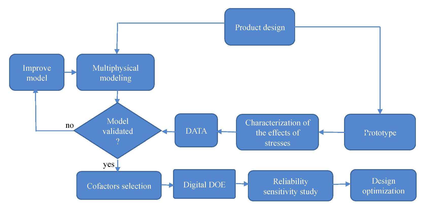
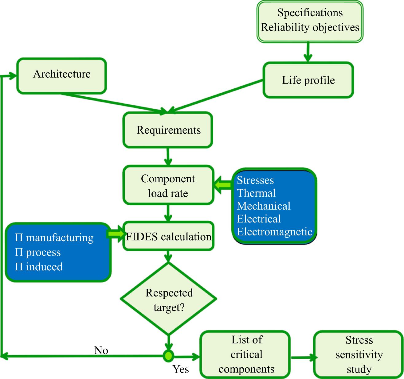
response of the model and measurements obtained on a prototype tested under mechanical or thermomechanical loads. An optimization method can be used to adjust design parameters and reduce the model and prototype response discrepancies and validate the model. Validation of the failure mechanism model is done by comparing the failure predictions to the failures found in tests. The design factors having a strong effect on the system failure mechanism are then identified with a screening method. A plan of numerical experiments makes it possible to develop a metamodel. This metamodel makes it possible to improve design by minimizing the effects of variability in design factors while maximizing reliability. The flow chart of this approach is shown in Figure 1.1.
CASE STUDY.–
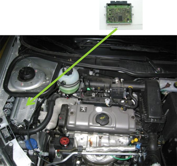
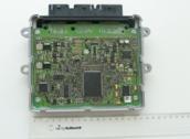
A case study based on an engine control unit (ECU) further illustrates this approach. This electronics system is located under the hood near the power train system (Figure 1.2). The ECU performs the analogical and digital electronic functions which control the thermal engine set points.
Figure 1.1. Flow chart of the reliability-based design optimization methodology
The ECU is an embedded mechatronic system that must operate with a reliability rate of 0.9999 for a 15-year period of use.
What is new in the architecture is a large microcontroller component with a large number of pins at a very fine pitch.
According to an analysis of the life profile, the stresses that can cause failures in the product components are the vibrations and thermal cycles accumulated during activation cycles.
To optimize the design of the ECU by reliability, a finite element model of the printed circuit board fixed by screws to its housing is developed. This model is validated by comparing the response of the model (displacements of the printed circuit during the application of temperature cycles) to the performance of a prototype under thermal loads.
1.2.1. Risk assessment using predictive reliability calculations
Predictive reliability calculations are used to assess the electronic system failure rate very early in its development. In these calculations,
Figure 1.2. ECU located under the hood
electronic component failures are assumed to be independent and random occurrences. Intrinsic failures caused by fatigue, wear or technological limitations are not considered. Figure 1.3 schematically shows the different steps of a predictive reliability calculation.
The guidelines used to assess predictive reliability in the embedded mechatronics industry are the MIL HDBK 217F standard and the UTE C 80-810 (RDF 2000) standard. These guides are accepted by most OEMs of the automotive industry. However, they have limitations. These are drawbacks – for example, they are not recent (MIL HDBK 217 standard was set up in the 1990s and the RDF 2000 standard in 2000) and they are not kept up to date. Their reliability predictions are not closely correlated with recent field return data [BNA 05]. In order to make better predictions available, Chapter 2 of this volume outlines the FIDES standard [GRO 09]. FIDES, founded in 2009, has proven to be useful in the fields of defense and aeronautics. It is updated regularly and so continues to evolve. Figure 1.3 demonstrates how to use FIDES standard.
Figure 1.3. The different stages of a FIDES forecast reliability calculation
CASE STUDY.–
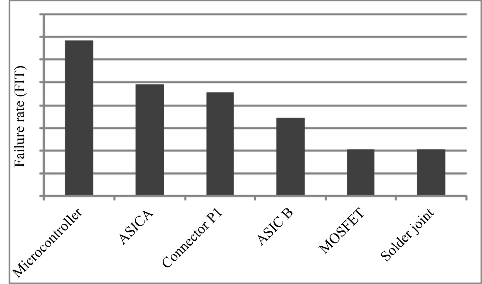
Figure 1.4 displays the failure rates expressed in failure in time (FIT) (1 FIT equals one failure per 109 h) of the components of the ECU having a high predictive failure rate. These are, by decreasing order of importance:
– the microcontroller;
– an application-specific integrated circuit (ASIC);
– a connector;
– a power transistor (MOSFET);
– etc.
Figure 1.4. Predictive failure rates (1 FIT equals one failure per 10–9 h) of the ECU critical components
1.2.2. Identifying elements that are critical for the reliability of the system
The elements that are critical for reliability are components that under the conditions of use are likely to have intrinsic failures (wear, aging, fatigue and corrosion). These are either innovative components
lacking sufficient information as to their robustness, or components that have been known by field returns as having a high failure rate.
Design elements that are critical for reliability are identified by checking the Bill of Materials (BOM) for the system. These critical components are listed in a document called the reliability matrix. This document describes, for each critical component, the expected modes and mechanisms of failure as well as the stresses that have a significant effect on these failures. The tests that are necessary to verify the robustness of the design elements with regard to the stresses causing failures are also documented. These tests constitute the reliability validation plan. The procedure for identifying elements critical for reliability is as follows:
– identify the expected failure modes of the critical part in operation (this means describing failure symptoms such as open circuit, short circuit, leakage current, parameter drift, degradation, etc.);
– describe the physical appearance of the defect (what is observed on the part when failure is analyzed: fissure, wear, oxidation and contamination) to clarify the way in which a part has failed;
– identify the expected failure mechanism (this means the physical and chemical causes of failure: fatigue, breakage, creep, deformation, wear, degradation due to exposure to solar or electromagnetic radiation, chemical corrosion, electromigration, electrostatic discharge, electrical overstress, insulation breakage, etc.);
– identify the stresses which trigger the failure mechanism (temperature level, number of thermal cycles, duration of exposure to ultraviolet (UV) radiation or moisture, number of dew cycles, current density amplitude, electric potential level, number of friction cycles, number of mechanical shocks, strength and duration of vibrations, number of pressure cycles, duration of exposure to corrosive agents, etc.);
– define the test which will lead to this failure mechanism;
– outline the test protocol (equipment and procedures) to track functioning failures;
– report whether the acceleration factor of the failure mechanism is known or not.
CASE STUDY.–
Table 1.1 displays the ECU reliability matrix.
The critical element is the microcontroller. This component, housed in a plastic quad flat package (PQFP), has wide dimensions (40 mm× 28 mm) and a fine lead pitch (0.5 mm). It is the first time this component is included in the BOM of an ECU. The potential failure risk for this component is the breakage of the solder joints connecting its leads to the printed circuit board (PCB). This failure mechanism may be due to fatigue caused by the accumulation od thermomechanical stresses. The stresses provoking this failure mechanism are the accumulation of temperature variation cycles.
Risk 1
Part at risk
Expected Failure Mode
Defect Signature
Stress triggering failure mechanism
Expected failure mechanism
Stress governing failure mechanism
How to test for this failure mode
Device to be tested
Microcontroller
Open circuit
Broken solder joint
Thermo-mechanical stress
Breakage of solder joint due to fatigue
Temperature variations
-40/125°C1h/1h thermal shocks
Printed circuit board in its housing
1.2.3. Determination of the distribution of stresses leading to failures
The reliability matrix lists for each expected failure mode the stress or the combination of stresses which are likely to have a strong effect on the failure. To determine the distribution of the stresses that will be required to study the robustness of the critical components, the operational conditions (standard and worst case uses) and environmental conditions (thermal and mechanical stresses applied globally to the vehicle (climate, vibrations, etc.) and locally to the subsystem) are analyzed. Thermal or vibratory measurements may also be performed.
Table 1.1. ECU reliability matrix
12 Embedded Mechatronic Systems 1
CASE STUDY.–
The vehicle has an expected life duration of 15 to 20 years depending on the type of vehicle and the manufacturer. The total distance traveled by the vehicle during its lifetime is 200,000 km. The number of hours in operation is approximately 9,000 h. The reliability requirements of the vehicle may be expressed as a maximum field return rate during the warranty period, a maximum proportion of defective devices per year, a percentage of cumulative failure after 10 or 15 years, or a warranty period lasting 15 years.
The ECU is a subsystem of the vehicle. Its architecture is designed to perform specified functions. The ECU consists of three subassemblies: an electronic board, a mechanical housing providing protection and sealing and a connector. Figure 1.5 shows schematically how the reliability requirements of the ECU fit into those of the vehicle and how the reliability of the ECU depends on the reliability of its components and their interconnections. It also displays the factors which at various levels have an impact on the expected failure mechanism.
Figure 1.5. Diagram describing ECU reliability at various architecture levels
Each time the vehicle is used, thermal loads are applied on the ECU board. During a duty cycle, the temperature of the ECU components varies from an initial temperature to a final temperature.
The initial temperature is the temperature of the vehicle when it is parked (for example 15°C). The final temperature is the equilibrium temperature reached by the ECU board when the vehicle is in the operating mode (for example 75°C). For each standard duty cycle, the variation in temperature of the components is on average 60°C. These temperature cycle loads create thermomechanical stresses on the solder joints of the ECU components. These thermomechanical stress cycles wear the solder joints out, producing cracks that cause connection failures. The parameters to optimize the reliability of solder joints depend on the manufacturing process (choice of the solder paste, controlling the conditions under which the solder paste is deposited and the conditions of thermal reflow) as well as design variables such as the dimensions of the printed circuit solder lands.
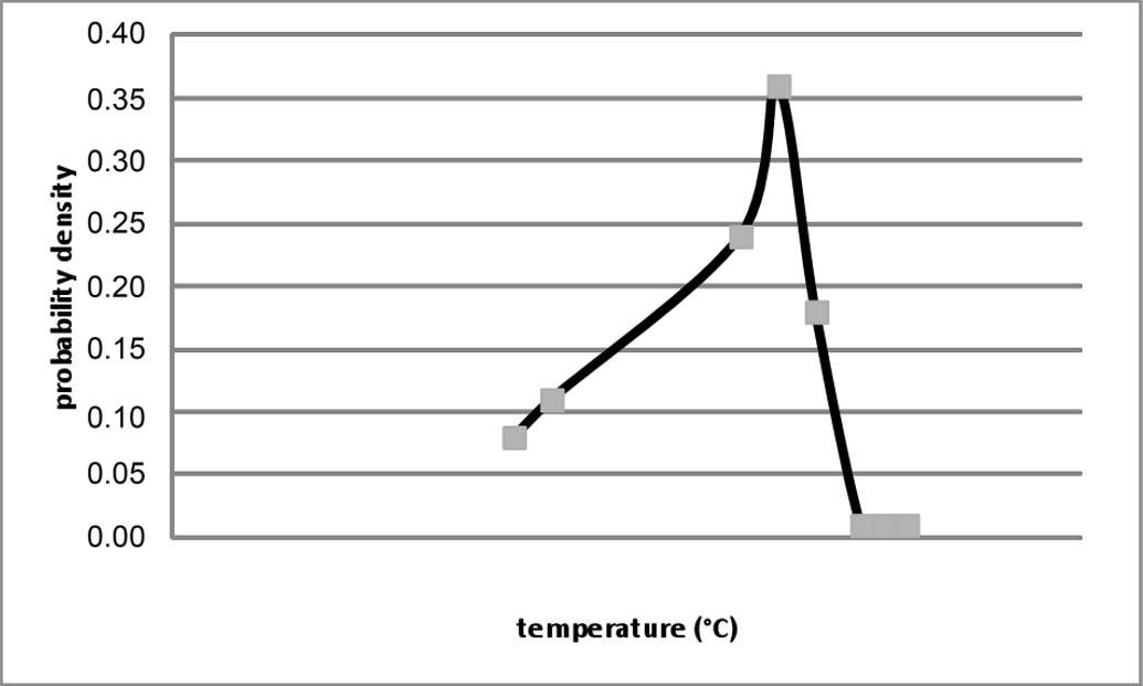
To determine the distribution of the stresses causing the expected solder joint failure mode, the magnitude and number of temperature cycles applied on the ECU components during a standard vehicle lifetime are determined. The amplitude of the thermal cycles is set from temperature measurements on instrumented vehicles and climatic data statistics. Figure 1.6 shows the probability density of the temperature board near the components of the ECU. The number of cycles is extracted from the ECU mission profile.
Figure 1.6. Density probability of temperature near the components of the ECU
1.2.4. Determining the critical effect of stresses
Characterization of the effect of stresses on the structural elements is used to understand the failure mechanisms of mechatronic devices. Thermal stresses and vibrations create displacements which are either in the plane or out of the plane of the structural elements. Optical methods are particularly efficient to characterize these displacements because they are contactless and not intrusive. These methods are able to consider the whole device while having a very good resolution.
CASE STUDY.–
Stresses applied on the ECU have two origins: temperature and vibrations. The power train system and the vehicle movement are sources of oscillations which deform the ECU elements. These cyclic deformations risk damaging solder joints of electronic components, condensers, terminals or connectors. Displacements caused by cyclic vibrations should be restrained. To limit the PCB displacements, the printed circuit is screwed into the casing. This increases the stiffness of the circuit board and its resonant frequency. The ECU microcontroller, which has 256 input/output pins at a 0.5 mm pitch, is placed in the middle of the PCB to facilitate routing.
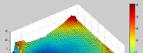
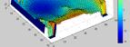
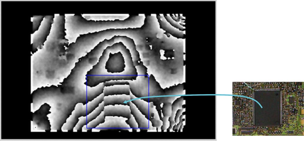
To evaluate the potential risks on reliability of this component location and orientation, the out-of-plane displacements are characterized when the assembled printed circuit board is exposed to temperature variations. These displacements are studied by speckle interferometry which is a full field high-resolution holographic method (Chapter 4). Figure 1.7 shows the full-field images obtained during the cooling of the board. A break in the alignment of the fringes can be observed on the microcontroller. This break reveals a change in the out-of-plane displacements.
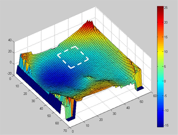
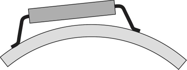
Figure 1.8 shows the deformations of the PCB. The position of the five screws is visible (one in the center and one at each corner). The position of the microcontroller corresponds to the dotted line. When the board is exposed to temperature variations, the printed circuit flexes but the central screw locally prevents any displacements. This leads to the PCB bending. The break which is observed in the fringes
(Figure 1.7) shows that the body of the microcontroller does not move. The leads of the component have to adapt to the local change of curvature. Strong mechanical stresses are applied to the solder joints which attach the leads to the copper prints on the circuit (Figure 1.9). Such cyclic stresses can set up traction forces in the pins and shear forces in the joints leading to fissuring of the solder joint and loosening of the pin. This causes an open circuit.
1.7. ECU spatial distribution of fringes revealing out-of-plane displacements
Figure 1.8. Out-of-plane displacements (dotted line: microcontroller position). For a color version of this figure, see www.iste.co.uk/elhami/embedded1b.zip
Figure
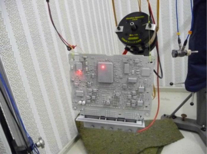
A second optical technique which characterizes the effect of stresses is three-dimensional (3D) laser vibrometry (Figure 1.10). In this technique, the structural elements of the mechatronic devices are submitted to vibrations by an external device and their three-dimensional movements are measured using Doppler laser beams. The dynamic response of the device is characterized using meshing. This optical technique is applied to the ECU to analyze modal deformations of the board and the components. Different integration levels are studied: bare PCB, board equipped with its components and board incased in its housing.
A third optical technique used to measure the mechanical deformations caused by variations in temperature is the correlation of digital image (CDI). This technique is used to measure the coefficient
Figure 1.9. Diagram representing how deformations affect the lead solder joints
Figure 1.10. Characterization of ECU by 3D laser doppler vibrometry
of thermal expansion of the two critical elements of the ECU: the microcontroller and the PCB. CDI consists of seizing successive images of the deformations of the part when it is submitted to thermal changes. This technique is sensitive. It provides useful information for failure mechanism modeling.
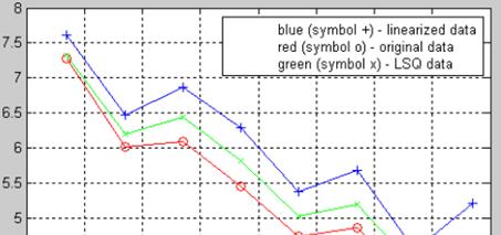
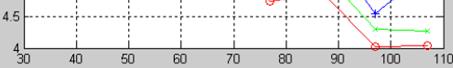
The displacement graphs obtained show that the movements of the different points (printed circuit and component in horizontal and vertical directions) do not vary linearly along the device. Certain expansions are not constant. This means that the global value of the coefficient of thermal expansion obtained on the scale of the device varies from one point to another according to the materials present in the respective zones within the structures tested. The overall calculated values, on average 35 × 10 6 K 1 for the printed circuit and 5.1 × 10 6 K 1 for the microcontroller, vary according to the difference between the initial and final temperatures (Figure 1.11).
Variation de température (K) Coefficient d’expansion thermique
Variation de température (K)
Temperature variations (K)
Temperature variations (K)
Figure 1.11. ECU thermal expansion coefficient relative to temperature variation: a) horizontal direction and b) vertical direction. For a color version of this figure, see www.iste.co.uk/elhami/embedded1b.zip
1.2.5. Inducing failures for failure mechanism analysis
In mechatronics industry design, reliability of a system is usually tested using a pass/fail endurance test, or life test. This test is typically done on a sample of parts. The stresses applied in these tests are similar to those occurring in use functioning. An acceleration factor is used to adapt the test duration to the system expected life in real use.