EMBEDDED DISCRETE FRACTURE MODELING AND APPLICATION IN RESERVOIR SIMULATION
KAMY SEPEHRNOORI
Hildebrand Department of Petroleum and Geosystems Engineering, The University of Texas at Austin
YIFEI XU
Hildebrand Department of Petroleum and Geosystems Engineering, The University of Texas at Austin, now with ExxonMobil Upstream Research Company
WEI YU
Sim Tech LLC
Series Editors
BAOJUN BAI AND ZHANGXIN CHEN
To my sisters Mahin Dokht and Parvin Dokht Sepehrnoori
Kamy Sepehrnoori
To my parents Zhongzheng Xu and Lihong Song and my wife Yue Zhang
Yifei Xu
To my parents Zhongzhao Yu and Ruie Sun and my in-laws Guilao Wu and Chunyun Tang and my wife Kan Wu
Wei Yu
Elsevier
Radarweg 29, PO Box 211, 1000 AE Amsterdam, Netherlands
The Boulevard, Langford Lane, Kidlington, Oxford OX5 1GB, United Kingdom 50 Hampshire Street, 5th Floor, Cambridge, MA 02139, United States
Copyright © 2020 Elsevier B.V. All rights reserved.
No part of this publication may be reproduced or transmitted in any form or by any means, electronic or mechanical, including photocopying, recording, or any information storage and retrieval system, without permission in writing from the publisher. Details on how to seek permission, further information about the Publisher’s permissions policies and our arrangements with organizations such as the Copyright Clearance Center and the Copyright Licensing Agency, can be found at our website: www.elsevier.com/permissions
This book and the individual contributions contained in it are protected under copyright by the Publisher (other than as may be noted herein).
Notices
Knowledge and best practice in this field are constantly changing. As new research and experience broaden our understanding, changes in research methods, professional practices, or medical treatment may become necessary.
Practitioners and researchers must always rely on their own experience and knowledge in evaluating and using any information, methods, compounds, or experiments described herein. In using such information or methods they should be mindful of their own safety and the safety of others, including parties for whom they have a professional responsibility.
To the fullest extent of the law, neither the Publisher nor the authors, contributors, or editors, assume any liability for any injury and/or damage to persons or property as a matter of products liability, negligence or otherwise, or from any use or operation of any methods, products, instructions, or ideas contained in the material herein.
Library of Congress Cataloging-in-Publication Data
A catalog record for this book is available from the Library of Congress
British Library Cataloguing-in-Publication Data
A catalogue record for this book is available from the British Library
ISBN: 978-0-12-821872-3
ISSN: 0376-7361
For information on all Elsevier publications visit our website at https://www.elsevier.com/books-and-journals
Publisher: Candice Janco
Acquisitions Editor: Amy Shapiro
Editorial Project Manager: Andrea Dulberger
Production Project Manager: Sruthi Satheesh
Designer: Greg Harris
Typeset by Thomson Digital
5.1
5.2
4.5.3
5.3
5.4
5.2.1
5.2.2
6.1
5.3.1
5.3.2
5.4.1
5.4.2
5.4.3
5.4.4
6.1.1
6.1.2
6.1.3
7.
6.2
6.1.4
8.
7.3
6.2.1
6.2.2 EDFM
6.2.3
6.2.4
8.3
8.4
7.2.2
7.2.3
7.2.4
7.2.5
7.3.1
7.5.1
7.5.2
8.4.1
8.4.2 Case 2: Homogeneous reservoir with 41 natural fractures
8.4.3 Case 3: Reservoir with irregular geometry
8.5 Case studies for 3D unstructured grids using the EbFVM
8.5.1 Case 4: Tight gas reservoir with inclined hydraulic fractures
8.5.2 Case 5: 3D Reservoir with complex
9.1
9.2
9.3
Introduction
1.1 Conventional reservoirs
Most hydrocarbon reservoirs are, to some extent, fractured (Bratton et al., 2006; Fernø, 2012). A naturally fractured reservoir is defined as a reservoir where natural fractures have a significant influence on the fluid flow (Nelson, 2001). A large portion of the world’s oil and gas reserves are trapped in naturally fractured reservoirs (Bourbiaux, 2010). For example, carbonate reservoirs hold more than 60% of the proven oil reserves and 40% of the proven gas reserves (Total, 2017). Most carbonate reservoirs (around 80%) are naturally fractured (Total, 2017), including the Ghawar Field of Saudi Arabia, the largest conventional oil field in the world.
Natural fractures are typically formed along with certain geological processes, such as faulting, folding, and weathering (Fernø, 2012). An example of natural fractures is shown in Fig. 1.1. The patterns of natural fractures depict the local stress state at the time when the fractures were created. The length of natural fractures ranges from micrometers to several miles. Fractures can have permeability much higher than the surrounding matrix, or they can act as flow barriers. In different types of naturally fractured reservoirs, fractures might provide essential reservoir porosity, greatly enhance permeability, or create significant permeability anisotropy (Nelson, 2001).
1.2 Unconventional reservoirs
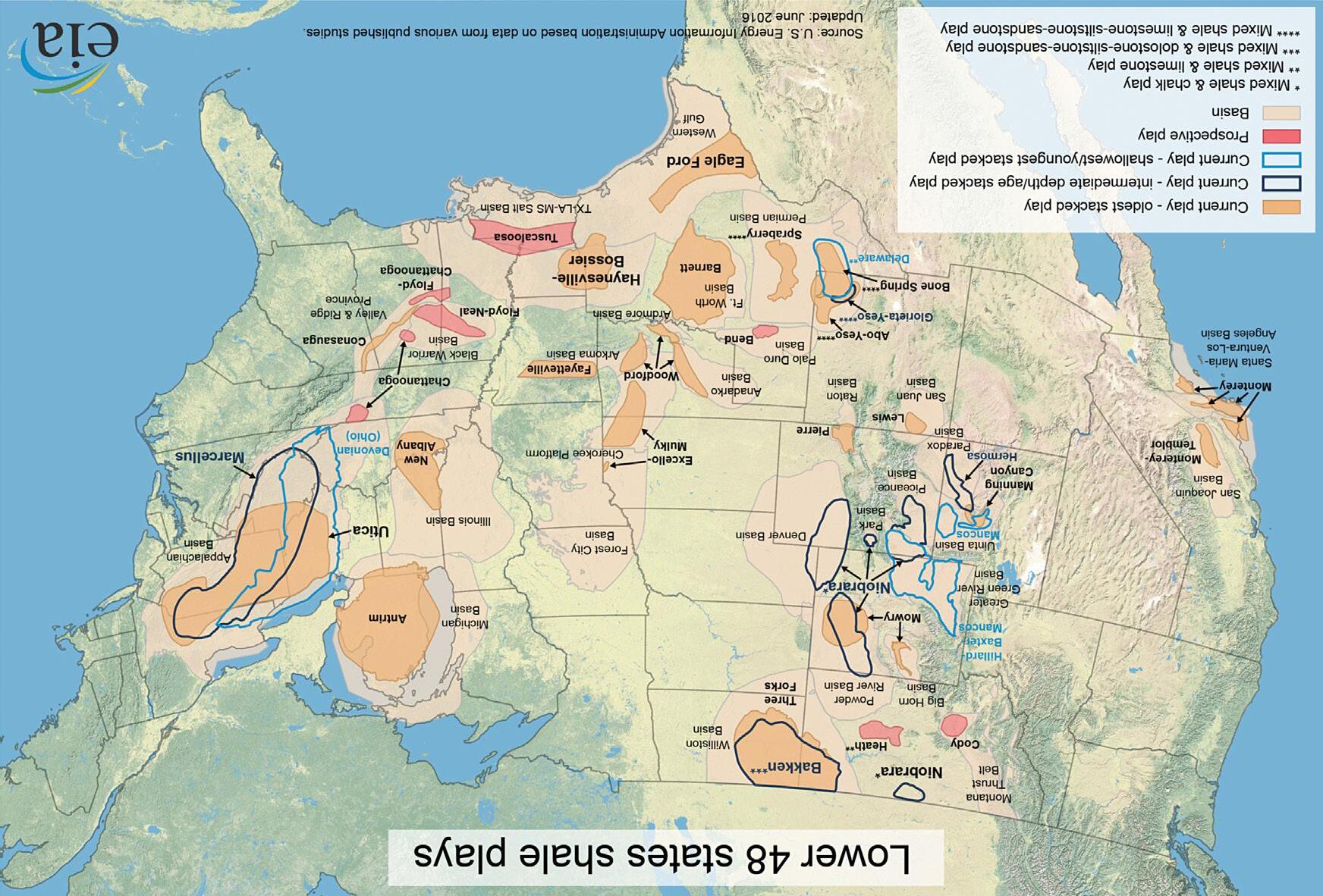
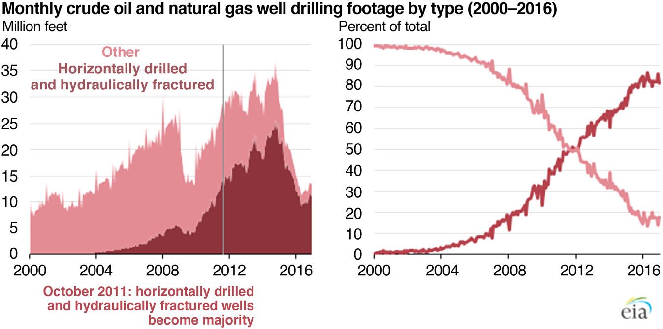
Besides natural fractures, induced fractures are also created using techniques such as hydraulic fracturing to improve the well performance. In the past, vertical wells were hydraulically fractured to enhance the fluid flow from the reservoir to the wellbore. In recent years, the combination of horizontal drilling and multi-stage hydraulic fracturing has made it possible to economically develop shale gas and tight oil resources with extremely low permeability and low porosity, as shown in Fig. 1.2. In 2016, hydraulically fractured horizontal wells contributed to 69% of all oil and natural gas wells drilled in the United States and account for about 83% of the total linear footage drilled, as shown in Fig. 1.3.
Embedded Discrete Fracture Modeling and Application in Reservoir Simulation. http://dx.doi.org/10.1016/B978-0-12-821872-3.00001-0
Copyright © 2020 Elsevier BV. All rights reserved.
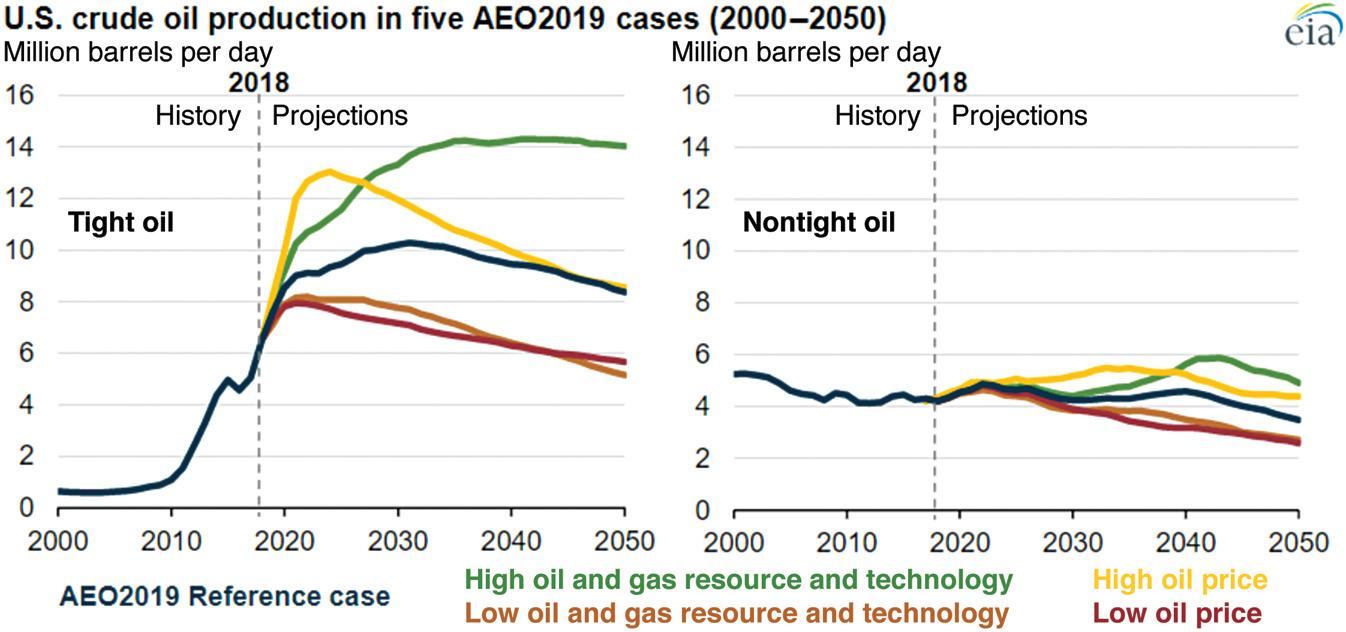
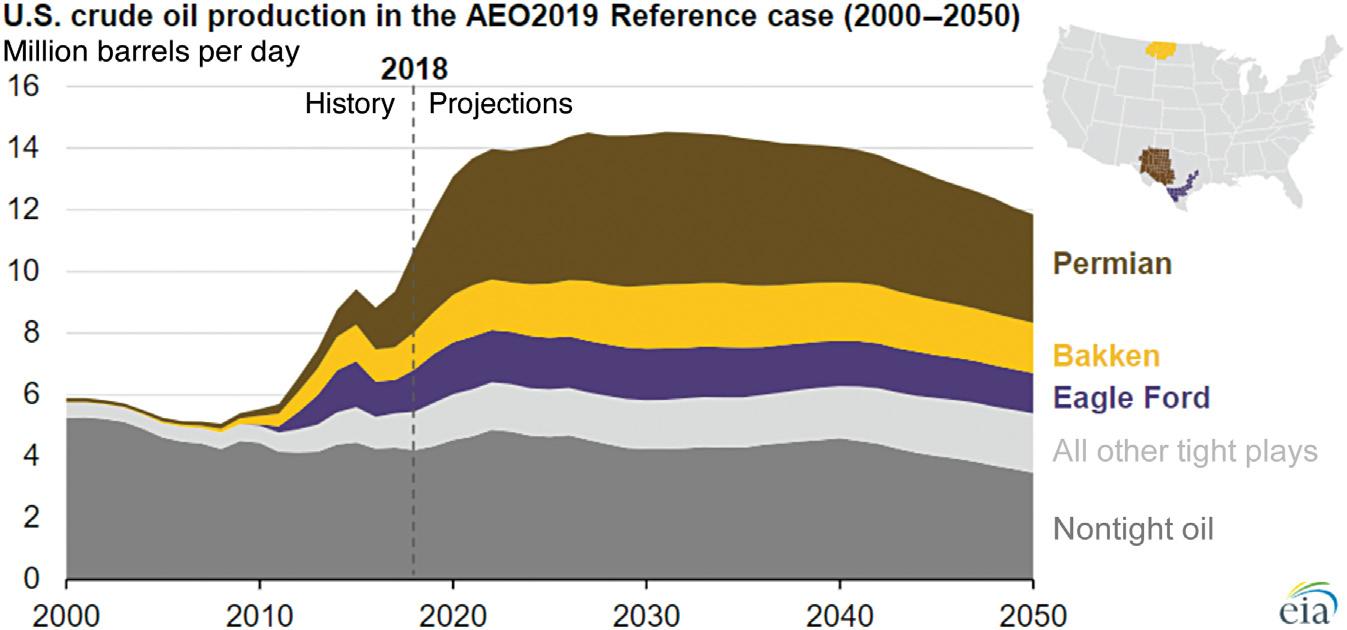
On the basis of US Energy Information Administration’s (EIA’s) Annual Energy Outlook (AEO) 2019, tight oil production in the United States was 6.5 million barrels per day in 2018, which accounted for 61% of total US oil production, as shown in Fig. 1.4. In addition, the tight oil production will continue to increase through 2030 and will reach more than 10 million barrels per day in the early 2030s. Furthermore, the improvement of drilling efficiency and reduction of cost will make tight oil resource development less sensitive to oil prices than in the past. As shown in Fig. 1.5, three major tight oil plays, Permian Basin, Bakken, and Eagle Ford, are expected to contribute half of the cumulative tight oil production through 2050. They account for approximately 41%, 19%, and 17% of US tight oil production in 2018, respectively.
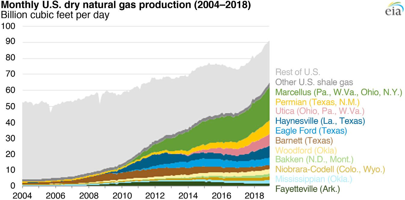
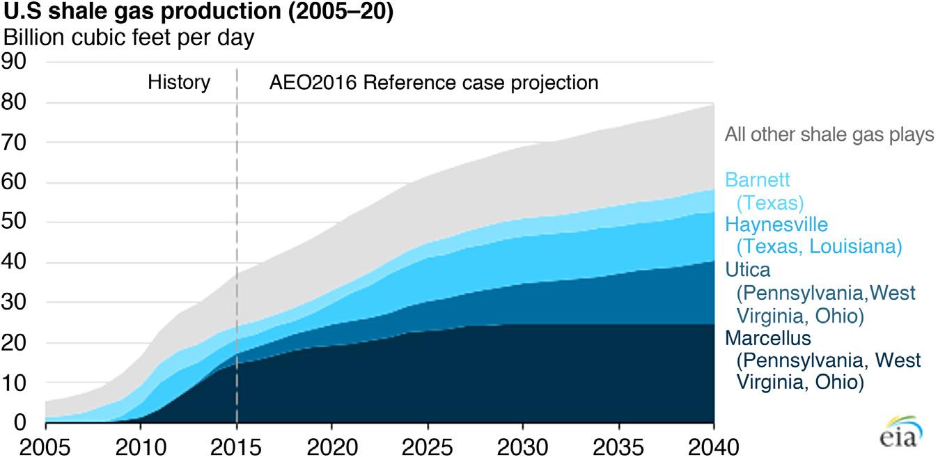
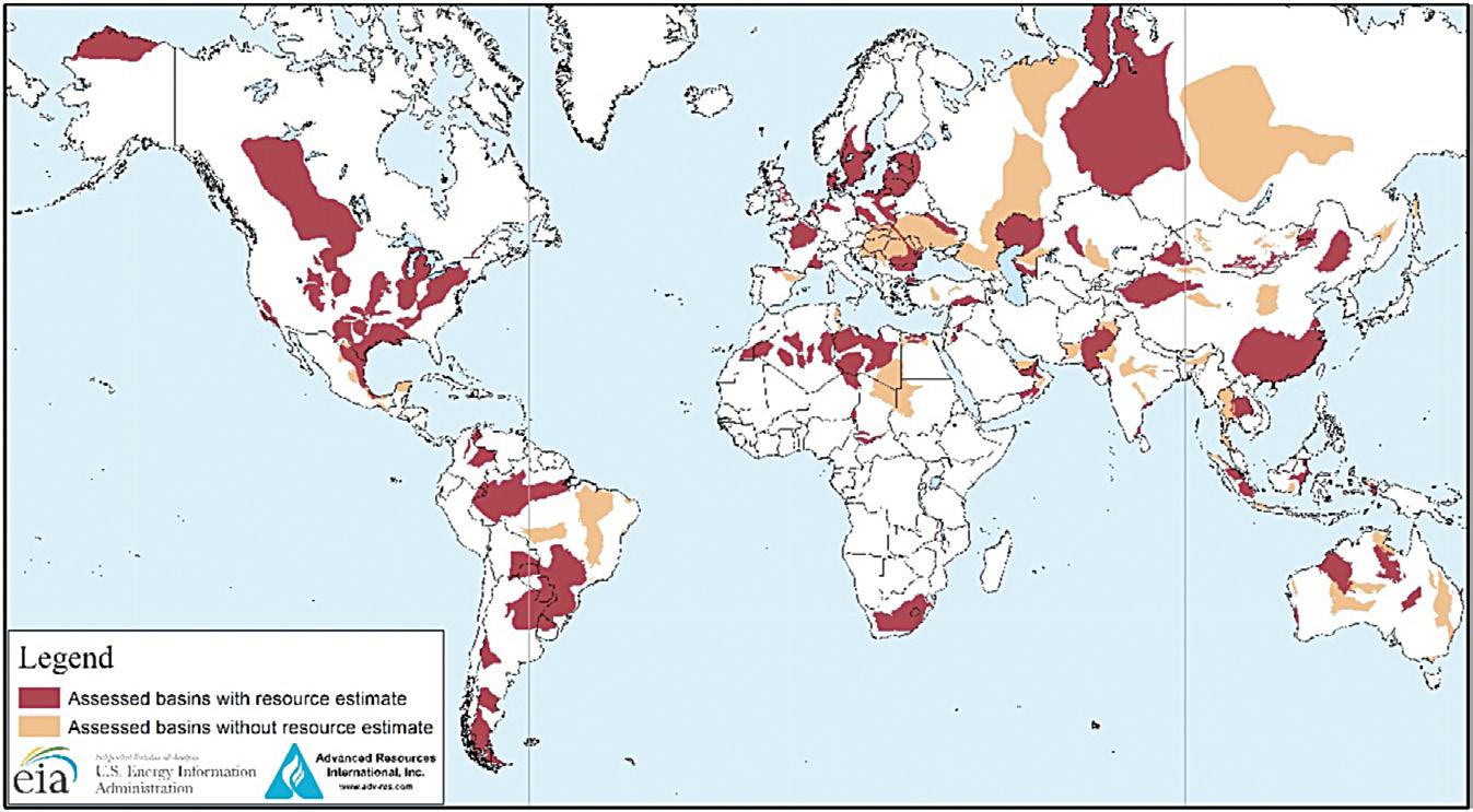
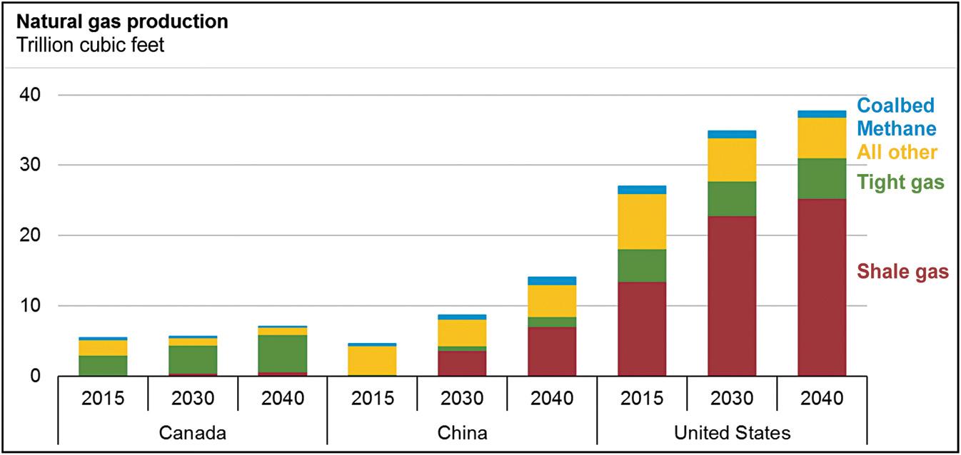
In addition, in 2018, US shale gas production was about 65 billion cubic feet per day, which accounted for 70% of total US dry gas production (EIA, 2019b), as shown in Fig. 1.6. However, in 2008, shale gas production only accounted for 16% of total US gas production. The most productive shale gas play is Marcellus. On the basis of projections in the EIA’s AEO 2016, shale gas production is expected to reach about 80 billion cubic feet per day by 2040, as shown in Fig. 1.7. Shale oil and gas resources are distributed all over the world (as shown in Fig. 1.8), and they are expected to be increasingly important in the next several decades, as shown in Fig. 1.9.
Figure 1.1 Photograph of fractured limestone (Geiger et al., 2009).
Figure 1.2 Shale gas and oil plays, lower 48 states (EIA, 2016a).
Figure 1.3 Monthly crude oil and natural gas well drilling footage by type (EIA, 2018).
Figure 1.4 US crude oil production in five AEO 2019 cases (EIA, 2019a).
Figure 1.5 Prediction of tight oil production of three major US tight oil plays in the AEO2019 Reference case (EIA, 2019a).
Figure 1.6 Monthly US dry natural gas production from 2004 to 2018 (EIA, 2019b).
Figure 1.7 US shale gas production from 2005 to 2040 (EIA, 2016b).
Figure 1.8 Basins with assessed shale oil and shale gas formations in the world as of May 2013 (EIA, 2015).
1.9 Outlook of natural gas supplies in Canada, China, and the United States (EIA, 2017).
1.3 Fracture complexity
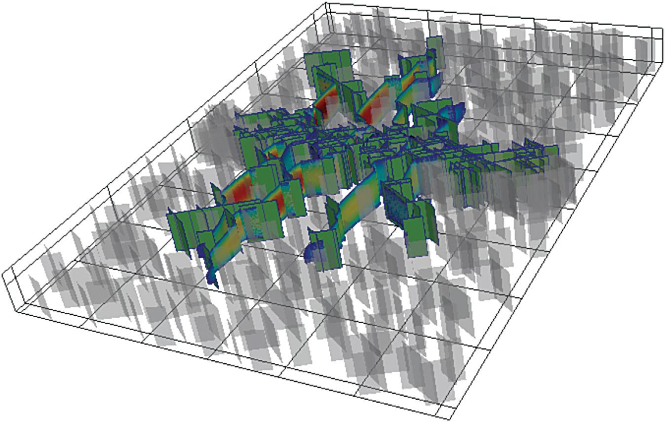
During a hydraulic fracturing operation, water, sand, and chemicals are injected into the formation. The injected fluid increases the pore pressure to break apart the rock and create conductive fractures in the formation. The created fractures vastly increase the contact surface area between the reservoir and the wellbore. The pre-existing natural fractures in the formation may also be connected to hydraulic fractures, forming complex fracture networks and further improving the reservoir contact (Maxwell et al., 2002; Fisher et al., 2004; Gale et al., 2007; Warpinski et al., 2009), as shown in Fig. 1.10.
Generally, there is high complexity in fracture geometry. In naturally fractured reservoirs, the orientation of natural fractures is quite complex, and complicated fracture networks are often created. In hydraulically fractured reservoirs, as fractures play a key role in reservoir fluid flow, a detailed description of fracture geometry becomes vital. The fracture dimensions and fracture geometry can be measured using fracture diagnostic techniques such as tiltmeter fracture mapping, microseismic fracture mapping, and distributed temperature sensing (Barree et al., 2002). They can also be predicted by fracture propagation models (Sneddon and Elliot, 1946; Settari and Cleary, 1986; Olson, 2008; Weng et al., 2011; Wu and Olson, 2014, 2015). The measurement and modeling results indicate the complexity of fracture geometry in both horizontal and vertical directions (Barree et al., 2002; Wu and Olson, 2014).
Figure
Figure 1.10 An example of complex hydraulic and activated natural fracture geometry, which was generated by a complex fracture propagation model ( Wu and Olson, 2015).
1.4 Effect of fractures on fluid flow
Complex hydraulic and natural fractures present challenges for reservoir modeling and production forecasting, which increases the difficulty of making appropriate plans to improve the recovery. Fractures may play different roles in the reservoir. Generally, because of the high permeability of fractures compared with the matrix, the fractures serve as main flow channels, and the fluid may preferably flow through fractures. Fractures can also create connectivity in the matrix, which enhances the effective reservoir permeability (Oda, 1985). In contrast, high-conductivity fractures also increase the permeability anisotropy. Furthermore, the recovery processes involved in fractured reservoirs may also be complicated. During water flooding, the injected fluid tends to flow through the fracture network, which limits the viscous displacement of oil from the matrix and leads to an early water breakthrough and an inefficient sweep (Bourbiaux, 2010; Lemonnier and Bourbiaux, 2010; Fernø, 2012). The counter-current spontaneous imbibition becomes an important mechanism in such processes, which depends on the capillary pressure curve and rock wettability (Fernø, 2012). The influence of fractures on other recovery processes such as gas drive, miscible gas flooding, and enhanced oil recovery has also been
discussed in the literature (Firoozabadi, 2000; Manrique et al., 2007; Lemonnier and Bourbiaux, 2010). The uncertainty related to the fractures also increases the difficulty of production forecasting. For example, the connectivity between fractures has a great impact on recovery, but it is not easy to directly measure the fracture network connectivity (Lee et al., 1993).
To help evaluate production strategies in fractured reservoirs, reliable numerical models are needed for the representation of hydraulic and natural fractures. However, owing to the complexity of fracture geometry and complexity of recovery processes related to fractured reservoirs, it is challenging to effectively simulate fractured reservoirs in numerical simulation. For very densely fractured reservoirs with well-connected fracture networks, a homogenization procedure can be used to include the impact of fractures in the effective matrix permeability (Oda, 1985; Lee et al., 2001). For the modeling of other fractured reservoirs, two classes of models are often used, that is, dual-continuum models and discrete fracture models (DFMs). In simulators, dual porosity and dual permeability approaches have been widely applied, and they present a high computational efficiency. However, they are not adequate for modeling large-scale fractures or capturing the influence of fracture connectivity (Karimi-Fard et al., 2004; Bourbiaux, 2010; Moinfar et al., 2011). DFMs, using the finiteelement method or finite-volume method, have been developed to tackle these challenges. Unstructured grids are used in most DFMs (Noorishad and Mehran, 1982; Karimi-Fard and Firoozabadi, 2003; Matthäi et al., 2005; Hoteit and Firoozabadi, 2006; Marcondes et al., 2010; Sandve et al., 2012; Hui et al., 2013; Karimi-Fard and Durlofsky, 2016) to explicitly represent each fracture. In these methods, conforming meshes are used, where the edges or faces of the matrix gridblocks around fractures match with the fracture surfaces.The usage of unstructured grids provides high flexibility in representing fracture geometries, and the result is more accurate compared with dual-continuum models. However, in real field studies, the application of unstructured-gridding-based DFMs is still limited because of the high complexity in gridding, especially around fracture intersections, and high computational cost (Du et al., 2017; Fumagalli et al., 2017).
1.5 Embedded discrete fracture model
In this book, we will introduce a new method, the EDFM, which is a combination of dual-continuum models and DFMs. In this method, the matrix is gridded regardless of the fracture geometry, and fractures are
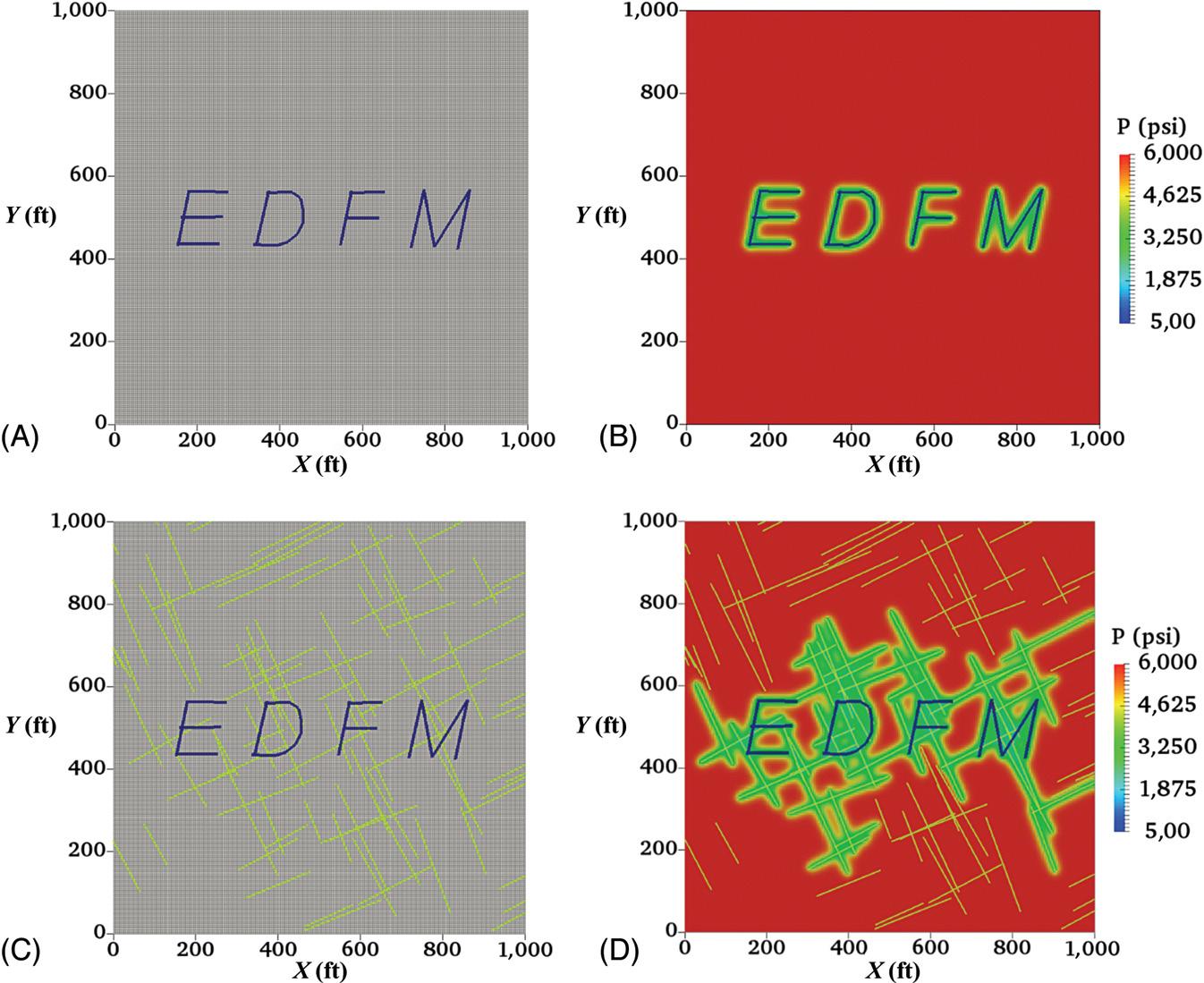
Figure 1.11 Two examples of the application of the EDFM method for easily and efficiently modeling complex fracture patterns using structured grids ( Yu et al., 2019). (A) A complex EDFM fracture pattern without natural fractures. (B) Pressure distribution after production simulation without natural fractures. (C) A complex EDFM fracture pattern with complex natural fractures. (D) Pressure distribution after production simulation with complex natural fractures.
discretized using the matrix gridblock boundaries, as shown in Fig. 1.11 Various types of fluid flows related to fractures are simulated by introducing special connections among matrix, fractures, and wellbores. Because in this method, the gridding of matrix is not affected by the locations or geometries of fractures, the common challenges involved in matrix gridding around fractures are effectively avoided, especially for cases with a large number of fractures or complex fracture geometries. It also offers the flexibility to conveniently simulate fractures with various types of computational grids. Furthermore, this approach is suitable for quick analysis of long-term reservoir performance under the influence of fracture uncertainties as no matrix re-gridding needs to be conducted after changing the fracture configuration. The EDFM has been successfully applied within several in-house and commercial reservoir simulators that have non-neighboring
connection functionality. Recent studies have shown the convenience and efficiency of the EDFM approach compared with other methods using grid refinement or unstructured gridding (Moinfar et al., 2014; Panfili et al., 2015; Du et al., 2017). Various types of realistic fracture geometries can be effectively handled with this method, as will be discussed in later chapters. The discretization of the matrix is of great importance for the implementation of the EDFM, as fracture discretization in the EDFM depends on the location of matrix block boundaries. Hence, the formulation and approach to implementation of the EDFM in different types of matrix gridding will be presented in this book as well. Overall, the primary objective of this book is to introduce the methodology to simulate complex fractures and related complex recovery processes using various types of computational grids with the EDFM.
1.6 Brief description of chapters
In Chapter 2, we introduce the complexities of naturally and hydraulically fractured reservoirs and the challenges they bring to reservoir simulation. Chapter 3 reviews current numerical technologies for modeling complex fractures in reservoir simulation, including dual-continuum models and DFMs. In Chapter 4, we present the basic methodology and formulations of the EDFM and its application in Cartesian Grids. The handling of dynamic fracture behaviors using the EDFM is discussed and demonstrated in Chapter 5. In Chapter 6, we present several field applications of the EDFM, including validation, history matching, sensitivity studies, and production forecasting. Chapter 7 discusses the application of the EDFM in geologically complex reservoirs represented by corner-point grids. The handling of geometrical calculation challenges is discussed in detail. In Chapter 8, we describe the methodology to apply the EDFM in twodimensional and three-dimensional unstructured grids using an elementbased finite-volume method.This demonstrates the flexibility of the EDFM in different types of computational grids. Finally, Chapter 9 concludes the book and includes recommendations based on our experience.
references
Barree, R.D., Fisher, M.K., Woodroof, R.A., 2002. A practical guide to hydraulic fracture diagnostic technologies. Paper SPE 77442. SPE Annual Technical Conference and Exhibition. San Antonio, Texas.
Bourbiaux, B., 2010. Fractured reservoir simulation: a challenging and rewarding issue. Oil Gas Sci. Technol. - Rev. IFP 65 (2), 227–238.
Bratton, T., Canh, D.V., Que, N.V., Duc, N.V., Gillespie, P., Hunt, D., Li, B., Marcinew, R., Ray, S., Montaron, B., Nelson, R., Schoderbek, D., Sonneland, L., 2006. The nature of naturally fractured reservoirs. Oilfield Rev. 18 (2), 4–23
Du, S., Liang, B., Yuanbo, L., 2017. Field study: embedded discrete fracture modeling with artificial intelligence in Permian Basin for shale formation. Paper SPE 187202. SPE Annual Technical Conference and Exhibition. San Antonio, Texas.
Fernø M.A., Enhanced Oil Recovery in Fractured Reservoirs, Introduction to Enhanced Oil Recovery (EOR) Processes and Bioremediation of Oil-Contaminated Sites, Rijeka, Croatia. 89.110 (2012): 89-110.
Firoozabadi, A., 2000. Recovery mechanisms in fractured reservoirs and field performance. J. Can. Pet. Technol. 39 (11), 13–17
Fisher, M.K., Heinze, J.R., Harris, C.D., Davidson, B.M., Wright, C.A., Dunn, K.P., 2004. Optimizing horizontal completion techniques in the Barnett Shale using microseismic fracture mapping. Paper SPE 90051. SPE Annual Technical Conference and Exhibition. Houston, Texas.
Fumagalli, A., Zonca, S., Formaggia, L., 2017. Advances in computation of local problems for flow-based upscaling in fractured reservoirs. Math. Comput. Simul. 137, 299–324.
Gale, J.F.W., Reed, R.M., Holder, J., 2007. Natural fractures in the Barnett Shale and their importance for hydraulic fracture treatments. AAPG Bull. 91 (4), 603–622
Geiger, S., Matthäi, S.K., Niessner, J., Helmig, R., 2009. Black-oil simulations for threecomponent, three-phase flow in fractured porous media. SPE J. 14 (2), 338–354
Hoteit, H., Firoozabadi, A., 2006. Compositional modeling of discrete-fractured media without transfer functions by the discontinuous Galerkin and mixed methods. SPE J. 11 (3), 341–352
Hui, M.-H., Mallison, B.T., Fyrozjaee, M.H., Narr, W., 2013. The upscaling of discrete fracture models for faster, coarse-scale simulations of IOR and EOR processes for fractured reservoirs. Paper SPE 166075. SPE Annual Technical Conference and Exhibition New Orleans. Louisiana
Karimi-Fard, M., Durlofsky, L.J., 2016. A general gridding, discretization, and coarsening methodology for modeling flow in porous formations with discrete geological features. Adv. Water Resour. 96, 354–372
Karimi-Fard, M., Durlofsky, L.J., Aziz, K., 2004. An efficient discrete-fracture model applicable for general-purpose reservoir simulators. SPE J. 9 (2), 227–236
Karimi-Fard, M., Firoozabadi, A., 2003. Numerical simulation of water injection in fractured media using the discrete-fracture model and the Galerkin method. SPE Reservoir Eval. Eng. 6 (2), 117–126
Lee, C.H.,Yu, J.L., Hwung, H.H., 1993. Fluid flow and connectivity in fractured rock. Water Resour. Manage. 7 (2), 169–184
Lee, S.H., Lough, M.F., Jensen, C.L., 2001. Hierarchical modeling of flow in naturally fractured formations with multiple length scales. Water Resour. Res. 37 (3), 443–455
Lemonnier, P., Bourbiaux, B., 2010. Simulation of naturally fractured reservoirs. State of the art. Oil Gas Sci. Technol. 65 (2), 239–262
Manrique, E.J., Muci, V.E., Gurfinkel, M.E., 2007. EOR field experiences in carbonate reservoirs in the United States. SPE Reservoir Eval. Eng. 10 (6), 667–686.
Marcondes, F., Varavei, A., Sepehrnoori, K., 2010. An element-based finite-volume method approach for naturally fractured compositional reservoir simulation. 13th Brazilian Congress of Thermal Sciences and Engineering-ENCIT. Uberlândia, MG, Brazil
Matthäi, S.K., Mezentsev, A., Belayneh, M., 2005. Control-volume finite-element two-phase flow experiments with fractured rock represented by unstructured 3D hybrid meshes. Paper SPE 93341. SPE Reservoir Simulation Symposium. The Woodlands, Texas
Maxwell, S.C., Urbancic, T.I., Steinsberger, N., Zinno, R., 2002. Microseismic imaging of hydraulic fracture complexity in the Barnett Shale. Paper SPE 77440. SPE Annual Technical Conference and Exhibition. San Antonio, Texas.