ElectricalSubmersible PumpsManual
Design,Operations,andMaintenance
SecondEdition GaborTakacs,Ph.D
GulfProfessionalPublishingisanimprintofElsevier 50HampshireStreet,5thFloor,Cambridge,MA02139,UnitedStates TheBoulevard,LangfordLane,Kidlington,Oxford,OX51GB,UnitedKingdom
Copyright 2018ElsevierInc.Allrightsreserved.
Nopartofthispublicationmaybereproducedortransmittedinanyformorbyanymeans, electronicormechanical,includingphotocopying,recording,oranyinformationstorage andretrievalsystem,withoutpermissioninwritingfromthepublisher.Detailsonhowto seekpermission,furtherinformationaboutthePublisher’spermissionspoliciesandour arrangementswithorganizationssuchastheCopyrightClearanceCenterandtheCopyright LicensingAgency,canbefoundatourwebsite: www.elsevier.com/permissions
Thisbookandtheindividualcontributionscontainedinitareprotectedundercopyrightby thePublisher(otherthanasmaybenotedherein).
Notices
Knowledgeandbestpracticeinthisfieldareconstantlychanging.Asnewresearchand experiencebroadenourunderstanding,changesinresearchmethods,professionalpractices, ormedicaltreatmentmaybecomenecessary.
Practitionersandresearchersmustalwaysrelyontheirownexperienceandknowledgein evaluatingandusinganyinformation,methods,compounds,orexperimentsdescribed herein.Inusingsuchinformationormethodstheyshouldbemindfuloftheirownsafetyand thesafetyofothers,includingpartiesforwhomtheyhaveaprofessionalresponsibility.
Tothefullestextentofthelaw,neitherthePublishernortheauthors,contributors,oreditors, assumeanyliabilityforanyinjuryand/ordamagetopersonsorpropertyasamatterof productsliability,negligenceorotherwise,orfromanyuseoroperationofanymethods, products,instructions,orideascontainedinthematerialherein.
LibraryofCongressCataloging-in-PublicationData AcatalogrecordforthisbookisavailablefromtheLibraryofCongress
BritishLibraryCataloguing-in-PublicationData AcataloguerecordforthisbookisavailablefromtheBritishLibrary
ISBN:978-0-12-814570-8
ForinformationonallElsevierpublicationsvisitourwebsiteat https://www.elsevier.com/books-and-journals
Publisher: JosephP.Hayton
AcquisitionEditor: KatieHammon
EditorialProjectManager: KatieChan
ProductionProjectManager: MohanapriyanRajendran Designer: MatthewLimbert
TypesetbyTNQBooksandJournals
PrefacetotheFirstEdition xv PrefacetotheSecondEdition xvii
1. Introduction
1.1ArtificialLifting 1
1.1.1GasLifting1 1.1.2Pumping2
1.1.3ComparisonofLiftMethods3
1.1.3.1LiftingCapacities3
1.1.3.2SystemEfficiencies5
1.1.3.3FurtherConsiderations6
1.2ShortHistoryofElectricalSubmersiblePumpingApplications 6
1.3BasicFeaturesofElectricSubmersiblePumpingInstallations 8 1.3.1Applications8 1.3.2AdvantagesandLimitations9 References 10
2. ReviewofFundamentals
2.1Introduction 11
2.2WellInflowPerformance 11
2.2.1Introduction11
2.2.2TheProductivityIndexConcept12
2.2.3InflowPerformanceRelationships14
2.2.3.1Introduction14
2.2.3.2Vogel’sInflowPerformanceRelationship Correlation15
2.2.3.3TheCompositeInflowPerformance RelationshipCurve16
2.3HydraulicFundamentals 21
2.3.1TubingFlowCalculations21
2.3.2ElectricalSubmersiblePumps23
2.3.2.1OperationalBasicsofCentrifugalPumps23
2.3.2.2SpecificSpeed27
2.3.2.3PumpPerformance28
2.3.2.4Cavitation31
2.3.2.5AxialThrustForces32
2.3.2.6AffinityLaws34
2.4.2AlternatingCurrentCircuits,AlternatingCurrentPower40 2.4.3Transformers42
2.4.4ElectricMotors44
2.4.4.1InductionMotors44
2.4.4.2PermanentMagnetMotors45 2.4.5ElectricCable47
2.5BasicsofSystemsAnalysis
3.2.1BasicFeatures57
3.2.1.1PumpPerformanceCurves59
3.2.2FloatingVersusFixedImpellerPumps65
3.2.3PumpTemperature67
3.2.4NovelPumpStageDesignandManufacturing69
3.3TheESPMotor
3.3.1Induction-TypeAsynchronousMotors72
3.3.1.1MotorConstruction72
3.3.1.2OperationalFeatures80
3.3.1.3MotorPerformance81
3.3.1.3.1MotorTesting82
3.3.1.3.2PerformanceCurves83
3.3.1.3.3StartupConditions84
3.3.1.4MotorTemperature87
3.3.1.4.1HeatTransferCalculations89
3.3.1.4.2AllowedMotorTemperature96
3.3.1.5High-PerformanceMotors97
3.3.2PermanentMagnetMotors98
3.3.2.1Introduction98
3.3.2.2MotorControllersforPermanentMagnet Motors98
3.3.2.2.1ScalarControl99
3.3.2.2.2VectorControl102
3.3.2.3ConstructionalDetails103
3.3.2.4OperationalFeatures105
3.3.2.5UltrahighSpeedPermanentMagnet MotorApplications109
3.3.2.6ComparisonwithInductionMotors111
3.3.2.7CaseStudies115
3.3.2.8Conclusions116
3.4TheProtectororSealSection 118
3.4.1MainFunctions118
3.4.2BasicOperation119
3.4.3MainParts121
3.4.3.1TheThrustBearing121
3.4.3.2IsolationChambers123
3.4.3.2.1Labyrinth-TypeChambers124
3.4.3.2.2BlockingFluids126
3.4.3.2.3Bag-TypeChambers127
3.4.3.2.4MetalBellowsTypeChambers128
4. UseofESPEquipmentinSpecialConditions
4.3.1Low-RatePumps162
4.3.2Wide-Operating-RangePumps163
4.4ProductionofGassyWells 164
4.4.1Introduction164
4.4.2Free-GasVolumeCalculations165
4.4.3PumpPerformanceDegradation172
4.4.3.1GasInterferenceinCentrifugalPumps172
4.4.3.2PerformanceCriteria175
4.4.4PossibleSolutions177
4.4.4.1UtilizationofNaturalGasSeparation177
4.4.4.1.1PumpSetBelowthe Perforations177
4.4.4.1.2UseofMotorShrouds178
4.4.4.2RotaryGasSeparators182
4.4.4.2.1AvailableTypes182
4.4.4.2.2TheRoleofInducers184
4.4.4.2.3SeparationEfficiencies186
4.4.4.3GasHandling189
4.4.4.3.1LegacyMethods189
4.4.4.3.2ModernSolutions191
4.4.5Conclusions194
4.5ProductionofAbrasiveSolids 195
4.5.1ConventionalPumps195
4.5.1.1Introduction195
4.5.1.2CharacteristicsofAbrasiveMaterials196
4.5.1.3SandProblemAreas198
4.5.1.3.1PumpErosion199
4.5.1.3.2AbrasioninRadialBearings199
4.5.1.3.3AbrasioninThrustWashers200
4.5.1.4Solutions200
4.5.1.4.1ReductionofRadialWear201
4.5.1.5PreventingSandAccumulationAbove thePump205
4.5.1.6Conclusions206
4.5.2SpecialPumpsforAbrasiveHandling207
4.6HighWellTemperatures 210
4.6.1TemperatureProblemsandSolutions210
4.6.2Geothermal,Steam-AssistedGravityDrainage Applications213
4.7Variable-FrequencyOperation 214
4.7.1PumpPerformanceatVariableSpeeds214
4.7.2Variable-SpeedDrives217
4.7.2.1ConstructionalDetails218
4.7.2.1.1TheRectifier218
4.7.2.1.2TheDirectCurrentControl Section219
4.7.2.1.3TheInverter219
4.7.2.2AvailableVariable-SpeedDriveTypes220
4.7.2.2.1“Six-Step”Variable-Speed Drive220
4.7.2.2.2PulsedWidthModulation220
4.7.2.2.3SineWaveGenerators223
4.7.2.2.4VectorControlDevices223
4.7.2.3OperationalCharacteristics224
4.7.3Variable-FrequencyGenerators225
4.7.4InteractionofVSD/VFGandESPUnits226
4.7.4.1Variable-FrequencyOperationof ElectricalMotors226
4.7.4.2InteractionofESPMotorsandVSD/VFG Units230
4.7.5BenefitsofUsingVariable-SpeedDrive/VariableFrequencyGeneratorUnits233
4.8OtherProblems 235 References 236
5. DesignofESPInstallations
5.1Introduction 241
5.2DataRequirements 241
5.3ConventionalDesign 242
5.3.1WellInflowCalculations243
5.3.2TotalDynamicHeadCalculations245
5.3.3SelectionofthePump246
5.3.3.1PumpSeries246
5.3.3.2PumpType247
5.3.3.3NumberofStages,PumpPower247
5.3.3.4CheckingthePump’sMechanicalStrength250
5.3.4SelectionoftheProtector250
5.3.5MotorSelection253
5.3.6SelectionofthePowerCable255
5.3.6.1CableLength256
5.3.6.2CableType256
5.3.6.3CableSize256
5.3.6.4CheckingMotorStartup259
5.3.7SwitchboardandTransformerSelection259
5.3.8MiscellaneousEquipment260
5.3.8.1DownholeEquipment260
5.3.8.2SurfaceEquipment260
5.4ConventionalDesignConsideringMotorSlip 266
5.4.1Introduction266
5.4.2InteractionoftheESPMotorandthePump267
5.4.3ChangesintheConventionalDesign269
5.4.3.1FindingActualMotorSpeed269
5.4.3.2FindingPumpHeadIncludingMotorSlip269
5.5GassyWellDesign 272
5.5.1InflowandFreeGasCalculations273
5.5.2CalculationofTotalDynamicHead274
5.5.3TheRestoftheDesignProcedure276
5.6DesignofaVariableSpeedDriveInstallation 283
5.6.1Introduction283
5.6.2PumpSelectionforVariableSpeedDriveService284
5.6.2.1DrivingFrequencyandtheNumberof Stages284
5.6.2.2CheckingPumpOperationattheMinimum LiquidRate285
5.6.3MotorSelection285
5.6.4SwitchboardandTransformers287
Contents
5.7DesignofaPermanentMagnetMotorInstallation 297
5.7.1DesignConsiderations297
5.7.1.1SelectionofthePump297
5.7.1.2SelectionofthePermanentMagnetMotor300
5.8ComparisonofInductionMotorandPermanentMagnet MotorInstallations 304 References 305
6. AnalysisandOptimization 307
6.1Introduction 307
6.2NODALAnalysis 307
6.2.1UsingtheHead RateCoordinateSystem309
6.2.1.1Single-PhaseCases310
6.2.1.1.1ConstantPumpingSpeed312
6.2.1.1.2VariablePumpingSpeeds315
6.2.1.1.3VariableWellheadPressures316
6.2.1.2MultiphaseCases318
6.2.1.2.1CalculationModel320
6.2.1.2.2Applications323
6.2.2UsingthePressure RateCoordinateSystem327
6.2.2.1Single-PhaseCases329
6.2.2.2MultiphaseCases334
6.3DeterminationofWellInflowPerformance 336
6.3.1TheConventionalMethod336
6.3.2UseofVariable-SpeedDrives339
6.3.3CalculationofBottomholePressures341
6.3.3.1Introduction341
6.3.3.2AnnularLiquidGradients342
6.3.3.2.1StaticConditions343
6.3.3.2.2FlowingConditions344
6.4PowerEfficiencyofESPInstallations 348
6.4.1PowerFlowintheESPSystem349
6.4.2EnergyLossesandEfficiencies351
6.4.2.1HydraulicLosses352
6.4.2.1.1TubingLosses352
6.4.2.1.2BackpressureLosses353
6.4.2.1.3PumpLosses354
6.4.2.1.4PowerLossinGasSeparator354
6.4.2.2ElectricalLosses354
6.4.2.2.1MotorLosses355
6.4.2.2.2CableLosses355
6.4.2.2.3SurfaceElectricalLosses356
6.4.3SystemEfficiency356
6.5OptimizationofElectricalSubmersiblePumpOperations 360
6.5.1Introduction360
6.5.2BasicsofEconomicOptimization361 References 365
7. Operation,Monitoring,andSurveillanceofElectrical SubmersiblePumpingSystems
7.1Introduction 367
7.2GuidelinesforRunningandPulling 367
7.2.1TransportationtotheWellsite368
7.2.2EquipmentInstallation368
7.2.2.1MotorInstallation368
7.2.2.2ProtectorInstallation369
7.2.2.3PumpInstallation369
7.2.2.4ESPCableInstallation370
7.2.2.5FinalMeasures370
7.2.3RunningEquipmentintheWell370
7.2.4SystemStartup371
7.2.5PullingESPEquipment372
7.3ProductionControl 373
7.3.1Introduction373
7.3.2TheEffectsofUsingWellheadChokes374
7.3.2.1TheNeedforWellheadChokes374
7.3.2.2UseofVariable-SpeedDriveUnits377
7.3.2.3SampleCalculations378
7.4MonitoringESPOperations 383
7.4.1Introduction383
7.4.2AcousticSurveys386
7.4.3DownholeMeasurements387
7.4.3.1InstrumentsandCommunications388
7.4.3.2MeasuredParametersandTheirUse389
7.4.4SurfaceControllers390
7.4.4.1Introduction390
7.4.4.1.1Fixed-SpeedDrives390
7.4.4.1.2Variable-SpeedDrives390
7.4.4.2ESPControllerFunctions391
7.5SurveillanceofESPOperations 391
7.5.1Introduction391
7.5.2KeyChallengesandRequirementsinProduction Operations393
7.5.3TheDigitalOilfield394
7.5.3.1AnOverview394
7.5.3.2DigitalOilfield:Step-by-StepProgression396
7.5.4ESPDataVisualization398
7.5.4.1WellStatusandWellGroupStatus398
7.5.4.2AnalysisUsingDataTrendVisualization401 References 404
8. FailuresandTroubleshooting
8.1Introduction
8.2.1GeneralCausesofFailures405
8.2.1.1VibrationsintheESPSystem407
8.2.2TypicalFailuresofSystemComponents409
8.2.3ESPTeardownAnalysis411
8.2.3.1Introduction411
8.2.3.2GeneralConsiderations412
8.2.3.3MotorInspection413
8.2.3.4ProtectorInspection415
8.2.3.5PumpInspection416
8.2.3.6CableInspection418
8.2.3.7InspectionofOtherEquipment418
8.2.4FailureTracking419
8.2.5Run-LifeEstimation420
8.2.5.1Introduction420
8.2.5.2Run-LifeMeasures421
8.2.5.3LifetimeDistribution424
8.3TroubleshootingElectricalSubmersiblePumping Installations 425
8.3.1InterpretationofAmmeterCharts425
8.3.2NodalAnalysisTechniques440
8.3.2.1Introduction440
8.3.2.2Applications440
8.3.2.3TheUseofMeasuredPumpIntakeand DischargePressures443 References 447
9. SpecialInstallations
9.1Introduction 449
9.2.1ProducingaSingleZone449
9.2.1.1ShroudedandHorizontalWell Installations449
9.2.1.2ParallellyConnectedInstallations450
9.2.1.3Series-ConnectedInstallations451
9.2.2DualZoneInstallations453
9.2.2.1ProductionCommingling453
9.2.2.2SelectiveProduction455
9.3AlternativeDeployedInstallations 456
9.3.1CableSuspendedUnits457
9.3.2CoiledTubingInstallations458
9.3.2.1CableLedOutsidetheCoiledTubing String458
9.3.2.2CableLedInsidetheCoiledTubingString460
9.3.3Thru-TubingDeployedSystems462
9.3.3.1RetrievableESPPumps462
9.3.3.2RetrievableESPSystems464
9.3.4Conclusions467
Thispageintentionallyleftblank
Chapter1 Introduction
1.1ARTIFICIALLIFTING
Usually,oilwellsintheearlystagesoftheirlivesflownaturallytothesurface andarecalled flowingwells.Flowingproductionmeansthatthepressureat thewellbottomissufficienttoovercomethesumofpressurelossesoccurring alongtheflowpathtotheseparator.Whenthiscriterionisnotmet,naturalflow endsandthewell dies.Thetwomainreasonsforawell’sdeathareasfollows: (1)theirflowingbottom-holepressuredropsbelowthetotalpressurelossesin thewell,or(2)pressurelossesinthewellbecomegreaterthanthebottom-hole pressureneededformovingthewellstreamtothesurface.Thefirstcaseoccurs becauseoftheremovaloffluidsfromtheundergroundreservoir;thesecond caseinvolvesanincreasingflowresistanceinthewell.Thiscanbecausedby (1)anincreaseinthedensityoftheflowingfluidasaresultofdecreasedgas productionor(2)variousmechanicalproblemssuchasasmalltubingsizeand downholerestrictions.
Artificiallifting methodsareusedtoproducefluidsfromwellsalready deadortoincreasetheproductionratefromflowingwells;severallifting mechanismsareavailabletochoosefrom.Theimportanceofartificialliftingis clearlyseenfromthetotalnumberofinstallations:accordingtooneestimate thereare w2millionoilwellsworldwideofwhichabout50%areplacedon somekindofartificiallift [1].
Onewidelyusedtypeofartificialliftmethodusesa pump setbelowthe liquidlevelinthewelltoincreasethepressuresoastoovercomethepressure lossesoccurringalongtheflowpath.Otherliftingmethodsuse compressed gas,injectedfromthesurfaceintothewelltubingtohelpliftingofwellfluids tothesurface.Althoughallartificialliftmethodscanbedistinguishedbased onthepreviousbasicmechanisms,thecustomaryclassificationissomewhat differentasdiscussedbelow.
1.1.1GasLifting
Allversionsofgasliftusehigh-pressurenaturalgasinjectedintothewellstreamatsomedownholepoint.In continuousflow gaslift,asteadyrateof gasisinjectedintothewelltubingaeratingtheliquidandthusreducingthe
http://dx.doi.org/10.1016/B978-0-12-814570-8.00001-5
pressurelossesoccurringalongtheflowpath.Becauseofthereductionofflow resistance,thewell’soriginalbottom-holepressurebecomessufficienttomove thegas/liquidmixturetothesurfaceandthewellstartstoflowagain. Therefore,continuousflowgasliftingcanbeconsideredasthecontinuationof flowingproduction.
In intermittentgaslift,gasisinjectedperiodicallyintothetubingstring wheneverasufficientlengthofliquidhasaccumulatedatthewellbottom.A relativelyhighvolumeofgasinjectedbelowtheliquidcolumnpushesthat columntothesurfaceasaslug.Gasinjectionistheninterrupteduntilanew liquidslugofthepropercolumnlengthbuildsupagain.Productionofwell liquids,therefore,isdoneby cycles.The plunger-assisted versionofintermittentgasliftusesaspecialfreeplungertravelingintothewelltubingto separatetheupward-movingliquidslugfromthegasbelowit.Theseversions ofgasliftphysicallydisplacetheaccumulatedliquidsfromthewell,a mechanismtotallydifferentfromthatofcontinuousflowgaslifting.
1.1.2Pumping
Pumpinginvolvestheuseofa downholepump toincreasethepressureinthe welltoovercomethesumofflowingpressurelosses.Itcanbefurtherclassified usingseveraldifferentcriteria,e.g.,theoperationalprincipleofthepumpused. However,thegenerallyacceptedclassificationisbasedonthewaythe downholepumpisdrivenanddistinguishesbetweenrodandrodlesspumping.
Rodpumping methodsutilizea string ofrodsconnectingthedownhole pumptothesurfacedrivingmechanism,which,dependingonthetypeof pumpused,makesanoscillatingorrotatingmovement.Thefirstkindsof pumpstobeappliedinwaterandoilwellswereofthe positivedisplacement typerequiringanalternatingverticalmovementtooperate.Thedominantand oldesttypeofrodpumpingis walking-beampumping,orsimplycalled sucker-rodpumping.Itusesapositivedisplacementplungerpump,andits mostwell-knownsurfacefeatureisapivotedwalkingbeam.
Theneedforproducingdeeperwellswithincreasedliquidvolumes necessitatedtheevolutionof long-stroke sucker-rodpumping.Several differentunitsweredevelopedwiththecommonfeaturesofusingthesame pumpsandrodstringsasinthecaseofbeam-typeunits,butwithsubstantially longerpumpstrokelengths.Thedesiredlongstrokesdidnotpermittheuseof awalkingbeam,andcompletelydifferentsurfacedrivingmechanismshadto beinvented.Thebasictypesinthisclassaredistinguishedaccordingtothe typeofsurfacedriveused:pneumaticdrive,hydraulicdrive,ormechanical drivelong-strokepumping.
Anewlyemergedrodpumpingsystemusesa progressingcavitypump thatrequirestherodstringtoberotatedforitsoperation.Thispump,likethe plungerpumpsusedinothertypesofrodpumpingsystems,alsoworksonthe principleofpositivedisplacementbutdoesnotcontainanyvalves.
Introduction Chapter j 1 3
Rodlesspumping methods,asthenameimplies,donothavearodstring tooperatethedownholepumpfromthesurface.Accordingly,othermeans (besidesmechanical)areusedtodrivethedownholepump,suchaselectricor hydraulic.Avarietyofpumptypesareutilizedwithrodlesspumpingincluding centrifugal,positivedisplacement,orhydraulicpumps. Electricsubmersible pumping (ESP)utilizesasubmergedelectricalmotordrivingamultistage centrifugalpump.Powerissuppliedtothemotorbyanelectriccablerunfrom thesurface.Suchunitsareideallysuitedtoproducehighliquidvolumes.
Theotherliftingsystemsintherodlesscategoryallemployahigh-pressure powerfluidthatispumpeddownthehole. Hydraulicpumping wasthefirst methoddeveloped;suchunitshaveapositivedisplacementpumpdrivenbya hydraulicengine,containedinonedownholeunit.Theengineormotorprovidesanalternatingmovementnecessarytooperatethepumpsection.The hydraulic turbine-driven pumpingunitconsistsofamultistageturbineanda multistagecentrifugalpumpsectionconnectedinseries.Theturbineissuppliedwithpowerfluidfromthesurfaceanddrivesthecentrifugalpumpathigh rotationalspeeds,whichliftswellfluidstothesurface.
Jetpumping,althoughitisahydraulicallydrivenmethodoffluidlifting, completelydiffersfromtherodlesspumpingprinciplesdiscussedsofar.Its downholeequipmentconvertstheenergyofahigh-velocityjetstreaminto usefulworktoliftwellfluids.Thedownholeunitofajetpumpinstallationis theonlyoil-wellpumpingequipmentknowntodaycontainingnomoving parts.
1.1.3ComparisonofLiftMethods
Althoughtherearesomeothertypesofartificialliftknown,theirimportanceis negligiblecomparedwiththosejustmentioned.Thus,thereisamultitudeof choicesavailabletoanengineerwhenselectingthetypeoflifttobeused. Althoughtheuseofmanyofthoseliftingmechanismsmayberestrictedor evenruledoutbyactualfieldconditionssuchaswelldepth,productionrates desired,andfluidproperties,usuallymorethanoneliftsystemturnsouttobe technicallyfeasible.Itisthentheproductionengineer’sresponsibilitytoselect thetypeofliftthatprovidesthe mostprofitable wayofproducingthedesired liquidvolumefromthegivenwell(s).Afteradecisionismadeconcerningthe liftingmethodtobeapplied,acompletedesignoftheinstallationforinitial andfutureconditionsshouldfollow.
1.1.3.1LiftingCapacities
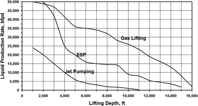
Toprovideapreliminarycomparisonoftheavailableartificialliftmethods, Fig.1.1 ispresentedwhereapproximatemaximumliquidproductionratesof thedifferentinstallationsaregiven [2] inthefunctionofliftingdepth.The figureshowsthreeliftingmechanismscapableofproducingexceptionally highliquidrates:gaslifting,ESP,andjetpumping.Asseen,gaslifting
FIGURE1.1 Maximumliquidproductionratesversusliftingdepthforvarioushigh-rateartificial liftmethods.
(continuousflow)canproducethegreatestamountsofliquidfromanydepth. Inallcases,liftingdepthhasaprofoundimportanceontheliquidvolume lifted,withwellratesrapidlydecreasingindeeperwells.
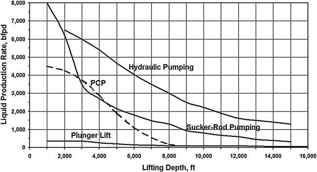
Fig.1.2,ontheotherhand,includesartificialliftmethodsofmoderate liquidproductioncapacity:hydraulicpumping,progressivecavitypumping, rodpumping,andplungerlifting.Inmostcases,liftingdepthnegativelyaffects theliftingcapacityoftheartificialliftingmethods.Itcanbenotedthatsuckerrodandprogressingcavitypumpsproduceverysimilarratesfromthelifting
FIGURE1.2 Maximumliquidproductionratesversusliftingdepthforvariousartificiallift methodsofmoderatecapacity.
depthrangeof3,000to6,000ft;thisfactcombinedwiththemuchlowerinvestmentandproductioncostsofPCPinstallationsexplainsthegreatpopularityofPCPapplicationsoverrodpumpingapplicationsinrecentyears.
1.1.3.2SystemEfficiencies
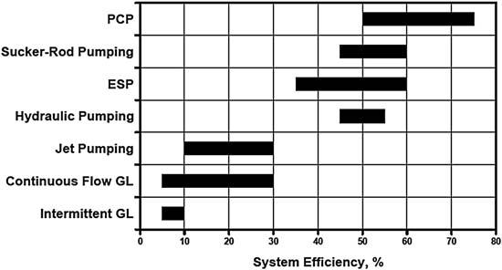
Energyefficienciesofpresent-dayartificialliftmethodsareverydifferentas shownin Fig.1.3.Theoverallefficiencyofanartificialliftinstallationisfound fromthetotalenergyrequiredtooperatethesystemandthehydraulicpower spentonliftingthefluidstothesurface.Theefficiencyistheproductofthe individualefficienciesofthesystem’scomponents.Thedecisivepartofthe overallefficiencyisduetotheeffectivenessoftheliftingmechanism,e.g., theenergyefficiencyofthepumpused,butpowerlossesinthewellandonthe surfacecanalsohaveagreatimpactonthefinalfigure.Thebasicprerequisite forhightotalenergyefficiency,therefore,istheapplicationofahighlyefficientliftingmechanism.
Themostenergy-efficientdeviceavailableforartificialliftingistheprogressingcavitypumpthatcanbemorethan70%efficientinconverting mechanicalenergytohydraulicwork.Becausetheuseofprogressingcavity pumpsinoilwellsrequiresrelativelysimplesurfaceanddownholeinstallationswithlowlevelsofenergylossesinsystemcomponents,PCPsystemsarethemostefficientamongtheartificialliftmethods.Nowonderthat, whereverwellconditionsfallintheirapplicationranges,thenumberofPCP installationsisgrowingveryfast.
Nextintheline,asshownin Fig.1.3,aresucker-rodpumpingandESP installationswithmaximumsystemefficienciesofabout60%.Althoughsuckerrodandelectricsubmersiblepumpsalonecanhavequitehighenergyefficiencies,bothliftingmethodsareplaguedbyhighdownholelossesintheir powertransmissionsystem.Inadditiontotheselosses,freegasenteringthe
pumpsdramaticallyreducestheirhydraulicoutputandconsequentlytheoverall systemefficiency.
Hydraulicpumpinginstallationsutilizingpositivedisplacementpumps usuallyhavepowerefficienciesaround50%.Jetpumpingandcontinuousflow gasliftingarerelativelyless-efficientartificialliftmethodswithmaximums around30%.Intermittentgaslifthasthelowestenergyefficiencyamongthe availableliftmethods.
1.1.3.3FurtherConsiderations
Theselectionoftheproperliftingmethodforagivenwellorfieldrequires morethancomparingtheproductioncapabilitiesandefficienciesofthe possiblesystems.Fluidproperties,fieldconditions,operatingandinvestment costestimates,andpossibleproductionproblemsarealltobeconsidered beforeafinaldecisionisarrivedat. Table1.1 provideshelpforapreliminary selectionofpossiblecandidatesandforeliminatingthosemethodsnotsuitable foractualconditions.
1.2SHORTHISTORYOFELECTRICALSUBMERSIBLE PUMPINGAPPLICATIONS
Unlikemostoftheotherartificialliftmethodssuchasgasliftingorsucker-rod pumping,forwhichinventioncannotbeattributedtoanypersonoranydefinite time,ESPwasinventedanddevelopedbyaRussiannamed ArmaisArutunoff inthelate1910s [3].In1911,hestartedthecompany“RussianElectrical DynamoofArutunoff”(itsacronym REDA stillbeingknownalloverthe world)anddevelopedthefirstelectricmotorthatcouldbeoperatedsubmersed inanoilwell.Togetfundingforthedevelopmentofhisideas, Mr.Arutunoff firstimmigratedtoGermanyin1919,andthenfinallysettledintheUnited Statesin1923.The USPatent hereceivedontheelectricalsubmersiblepump [4] wasissuedin1926andcoveredtheprincipalfeaturesofthisnewartificiallift method.ThefirstESPinstallationwassuccessfullyoperatedinthe ElDorado fieldinKansasin1926. Mr.Arutunoff movedtoBartlesville,Oklahoma,in1928 wherehestartedtheBartManufacturingCo.,laterreorganizedas REDAPump Co. in1930.
ThefirstESPunitsweredrivenbythree-phasetwo-poleelectricinduction motorsof53/800 or77/800 OD.Thebiggestmotorwasabout20ftlongand developed105HP.Directlyabovethemotora“sealunit”wasattached,the maintaskofwhichwastopreventtheleakageofwellfluidsintothemotor.On topofthesealunit,amultistagecentrifugalpumpliftedwellfluidstothe surface.ThecompleteESPunit(motor,seal,andpump)wasrunintothewell onthebottomofthetubingstring,electricitybeingsuppliedfromthesurface tothemotorbyaspecialthree-conductorcable.Eventoday,thesearethemain componentsofESPinstallations.Aftermorethan80yearsofoperation,the REDA Companyestablishedby Mr.Arutunoff,whoalonereceived90
TABLE1.1 MainFeaturesofArtificialLiftInstallations
ESP,electricsubmersiblepumping; PCP,progressingcavitypumping; SR,suckerrod. ModifiedafterLeaJF.Artificialliftselection.SPEpetroleumengineeringhandbook,vol.IV:SocietyofPetroleumEngineers;2007[Chapter10].