ElectricalSubmersible PumpsManual
Design,Operations,andMaintenance
SecondEdition GaborTakacs,Ph.D
2.4.2AlternatingCurrentCircuits,AlternatingCurrentPower40 2.4.3Transformers42
2.4.4ElectricMotors44
2.4.4.1InductionMotors44
2.4.4.2PermanentMagnetMotors45 2.4.5ElectricCable47
2.5BasicsofSystemsAnalysis
3.2.1BasicFeatures57
3.2.1.1PumpPerformanceCurves59
3.2.2FloatingVersusFixedImpellerPumps65
3.2.3PumpTemperature67
3.2.4NovelPumpStageDesignandManufacturing69
3.3TheESPMotor
3.3.1Induction-TypeAsynchronousMotors72
3.3.1.1MotorConstruction72
3.3.1.2OperationalFeatures80
3.3.1.3MotorPerformance81
3.3.1.3.1MotorTesting82
3.3.1.3.2PerformanceCurves83
3.3.1.3.3StartupConditions84
3.3.1.4MotorTemperature87
3.3.1.4.1HeatTransferCalculations89
3.3.1.4.2AllowedMotorTemperature96
3.3.1.5High-PerformanceMotors97
3.3.2PermanentMagnetMotors98
3.3.2.1Introduction98
3.3.2.2MotorControllersforPermanentMagnet Motors98
3.3.2.2.1ScalarControl99
3.3.2.2.2VectorControl102
3.3.2.3ConstructionalDetails103
3.3.2.4OperationalFeatures105
3.3.2.5UltrahighSpeedPermanentMagnet MotorApplications109
3.3.2.6ComparisonwithInductionMotors111
3.3.2.7CaseStudies115
3.3.2.8Conclusions116
3.4TheProtectororSealSection 118
3.4.1MainFunctions118
3.4.2BasicOperation119
3.4.3MainParts121
3.4.3.1TheThrustBearing121
3.4.3.2IsolationChambers123
3.4.3.2.1Labyrinth-TypeChambers124
3.4.3.2.2BlockingFluids126
3.4.3.2.3Bag-TypeChambers127
3.4.3.2.4MetalBellowsTypeChambers128
4. UseofESPEquipmentinSpecialConditions
4.3.1Low-RatePumps162
4.3.2Wide-Operating-RangePumps163
4.4ProductionofGassyWells 164
4.4.1Introduction164
4.4.2Free-GasVolumeCalculations165
4.4.3PumpPerformanceDegradation172
4.4.3.1GasInterferenceinCentrifugalPumps172
4.4.3.2PerformanceCriteria175
4.4.4PossibleSolutions177
4.4.4.1UtilizationofNaturalGasSeparation177
4.4.4.1.1PumpSetBelowthe Perforations177
4.4.4.1.2UseofMotorShrouds178
Contents
5.7DesignofaPermanentMagnetMotorInstallation 297
5.7.1DesignConsiderations297
5.7.1.1SelectionofthePump297
5.7.1.2SelectionofthePermanentMagnetMotor300
5.8ComparisonofInductionMotorandPermanentMagnet MotorInstallations 304 References 305
6. AnalysisandOptimization 307
6.1Introduction 307
6.2NODALAnalysis 307
6.2.1UsingtheHead RateCoordinateSystem309
6.2.1.1Single-PhaseCases310
6.2.1.1.1ConstantPumpingSpeed312
6.2.1.1.2VariablePumpingSpeeds315
6.2.1.1.3VariableWellheadPressures316
6.2.1.2MultiphaseCases318
6.2.1.2.1CalculationModel320
6.2.1.2.2Applications323
6.2.2UsingthePressure RateCoordinateSystem327
6.2.2.1Single-PhaseCases329
6.2.2.2MultiphaseCases334
6.3DeterminationofWellInflowPerformance 336
6.3.1TheConventionalMethod336
6.3.2UseofVariable-SpeedDrives339
6.3.3CalculationofBottomholePressures341
6.3.3.1Introduction341
6.3.3.2AnnularLiquidGradients342
6.3.3.2.1StaticConditions343
6.3.3.2.2FlowingConditions344
6.4PowerEfficiencyofESPInstallations 348
6.4.1PowerFlowintheESPSystem349
6.4.2EnergyLossesandEfficiencies351
6.4.2.1HydraulicLosses352
6.4.2.1.1TubingLosses352
6.4.2.1.2BackpressureLosses353
6.4.2.1.3PumpLosses354
6.4.2.1.4PowerLossinGasSeparator354
6.4.2.2ElectricalLosses354
6.4.2.2.1MotorLosses355
6.4.2.2.2CableLosses355
6.4.2.2.3SurfaceElectricalLosses356
6.4.3SystemEfficiency356
6.5OptimizationofElectricalSubmersiblePumpOperations 360
6.5.1Introduction360
6.5.2BasicsofEconomicOptimization361 References 365
7. Operation,Monitoring,andSurveillanceofElectrical SubmersiblePumpingSystems
7.1Introduction 367
7.2GuidelinesforRunningandPulling 367
7.2.1TransportationtotheWellsite368
7.2.2EquipmentInstallation368
7.2.2.1MotorInstallation368
7.2.2.2ProtectorInstallation369
7.2.2.3PumpInstallation369
7.2.2.4ESPCableInstallation370
7.2.2.5FinalMeasures370
7.2.3RunningEquipmentintheWell370
7.2.4SystemStartup371
7.2.5PullingESPEquipment372
7.3ProductionControl 373
7.3.1Introduction373
7.3.2TheEffectsofUsingWellheadChokes374
7.3.2.1TheNeedforWellheadChokes374
7.3.2.2UseofVariable-SpeedDriveUnits377
7.3.2.3SampleCalculations378
7.4MonitoringESPOperations 383
7.4.1Introduction383
7.4.2AcousticSurveys386
7.4.3DownholeMeasurements387
7.4.3.1InstrumentsandCommunications388
7.4.3.2MeasuredParametersandTheirUse389
7.4.4SurfaceControllers390
7.4.4.1Introduction390
7.4.4.1.1Fixed-SpeedDrives390
7.4.4.1.2Variable-SpeedDrives390
7.4.4.2ESPControllerFunctions391
7.5SurveillanceofESPOperations 391
7.5.1Introduction391
7.5.2KeyChallengesandRequirementsinProduction Operations393
7.5.3TheDigitalOilfield394
7.5.3.1AnOverview394
7.5.3.2DigitalOilfield:Step-by-StepProgression396
7.5.4ESPDataVisualization398
7.5.4.1WellStatusandWellGroupStatus398
7.5.4.2AnalysisUsingDataTrendVisualization401 References 404
8. FailuresandTroubleshooting
8.1Introduction
Thispageintentionallyleftblank
PrefacetotheFirstEdition
Electricalsubmersiblepumping(ESP)istheonlykindofartificialliftingfor whichtheoriginaltimeofinventionisknownexactlyandcanbeattributedtoone man, ArmaisArutunoff. HemadehisfirstexperimentsintheBakuoilfieldsat theCaspianSeainthelate1910s,andwaslaterthefounderofthecompany “RussianElectricalDynamoofArutunoff”whoseacronym REDA isstillvery wellknownallovertheworld.Arutunoff’s(whoalonereceivedabout90patents relatedtosubmersibleequipment)pioneeringworkstartedanindustrythattoday lifts w10%oftheworld’scrudeoilproduction.
Fromtheirearlydayson,ESPunitshaveexcelledinliftingmuchgreater liquidratesthanmostoftheothertypesofartificialliftandhavefoundtheirbest useinhigh-rateonshoreandoffshoreapplications.Continuoustechnological developmentinthelastalmost100yearshasenormouslymodifiedtheapplicationrangesforESPequipment.Highgasproduction,quicklychangingliquid productionrates,viscouscrudes,etc.,conditionsonceverydetrimentaltoESP operations,arenoweasilyhandledbypresent-dayunits.Alltheseendupinthe indispensabilityofESPequipmentinthepetroleumindustrynotonlytodaybut intheforeseeablefutureaswell.
Iwrotethisbookwiththeneedsofapetroleumengineeringgraduatestudent inmindandwiththeobjectiveofcoveringallaspectsofup-to-datetheoriesand practicesinESPtechnology.Whileworkingonthemanuscript,Iusedpartsof itinindustrialshortcoursesandIalwaysconsideredthefeedbackfrom participantswhenimprovingthematerial.Thisway,Ibelieve,thetarget audienceofthebookisevenbroaderandincludespracticingengineersaswell. Throughoutthetext,workedexampleshelpreadersunderstandbasicprinciples aswellasdesignandanalysisprocedures.
Thisbook,alongwithitstwopredecessors(ModernSucker-RodPumping, PennWell,1993and GasLiftManual,PennWell,2005),concludesmycoverage ofthethreemostimportantartificialliftmethods:sucker-rodpumping,gas lifting,andsubmersiblepumping.Becausethesearetheverytechnologiesused onthemajorityofartificiallyliftedoilwells,anyonestudyingthesebookswill havereadilyavailableacompleteandup-to-dateknowledgebaseencompassing themajorartificiallifttechnologies.Isincerelyhopethatreaderswillappreciate theadvantagesofauniformapproachandtreatmentofthedifferenttopics comingfromasingleauthor.
closeto300referencescitedinthetextprovethatallsignificantcontributionsto theadvancementofourindustryweredetectedandproperlyconsidered.
Whileresearchingforthebook,Ireceivedtremendousamountsofhelpfrom toomanyindividualstoname;theircontributionsaregratefullyappreciated.
GaborTakacs,PhD Budapest,May2017
Chapter1 Introduction
1.1ARTIFICIALLIFTING
Usually,oilwellsintheearlystagesoftheirlivesflownaturallytothesurface andarecalled flowingwells.Flowingproductionmeansthatthepressureat thewellbottomissufficienttoovercomethesumofpressurelossesoccurring alongtheflowpathtotheseparator.Whenthiscriterionisnotmet,naturalflow endsandthewell dies.Thetwomainreasonsforawell’sdeathareasfollows: (1)theirflowingbottom-holepressuredropsbelowthetotalpressurelossesin thewell,or(2)pressurelossesinthewellbecomegreaterthanthebottom-hole pressureneededformovingthewellstreamtothesurface.Thefirstcaseoccurs becauseoftheremovaloffluidsfromtheundergroundreservoir;thesecond caseinvolvesanincreasingflowresistanceinthewell.Thiscanbecausedby (1)anincreaseinthedensityoftheflowingfluidasaresultofdecreasedgas productionor(2)variousmechanicalproblemssuchasasmalltubingsizeand downholerestrictions.
Artificiallifting methodsareusedtoproducefluidsfromwellsalready deadortoincreasetheproductionratefromflowingwells;severallifting mechanismsareavailabletochoosefrom.Theimportanceofartificialliftingis clearlyseenfromthetotalnumberofinstallations:accordingtooneestimate thereare w2millionoilwellsworldwideofwhichabout50%areplacedon somekindofartificiallift [1].
Onewidelyusedtypeofartificialliftmethodusesa pump setbelowthe liquidlevelinthewelltoincreasethepressuresoastoovercomethepressure lossesoccurringalongtheflowpath.Otherliftingmethodsuse compressed gas,injectedfromthesurfaceintothewelltubingtohelpliftingofwellfluids tothesurface.Althoughallartificialliftmethodscanbedistinguishedbased onthepreviousbasicmechanisms,thecustomaryclassificationissomewhat differentasdiscussedbelow.
1.1.1GasLifting
Allversionsofgasliftusehigh-pressurenaturalgasinjectedintothewellstreamatsomedownholepoint.In continuousflow gaslift,asteadyrateof gasisinjectedintothewelltubingaeratingtheliquidandthusreducingthe
http://dx.doi.org/10.1016/B978-0-12-814570-8.00001-5
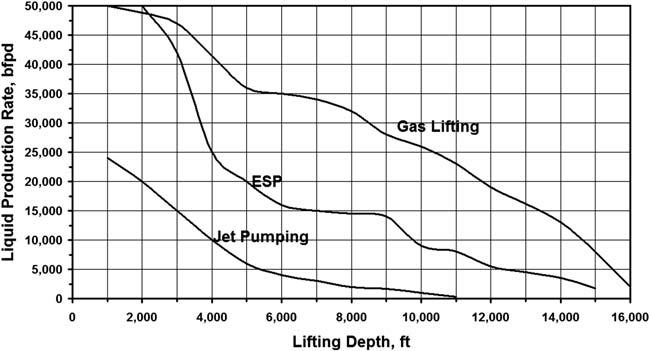
FIGURE1.1 Maximumliquidproductionratesversusliftingdepthforvarioushigh-rateartificial liftmethods.
(continuousflow)canproducethegreatestamountsofliquidfromanydepth. Inallcases,liftingdepthhasaprofoundimportanceontheliquidvolume lifted,withwellratesrapidlydecreasingindeeperwells.
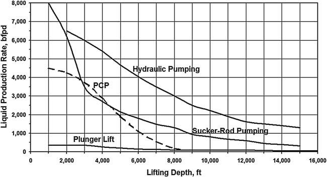
Fig.1.2,ontheotherhand,includesartificialliftmethodsofmoderate liquidproductioncapacity:hydraulicpumping,progressivecavitypumping, rodpumping,andplungerlifting.Inmostcases,liftingdepthnegativelyaffects theliftingcapacityoftheartificialliftingmethods.Itcanbenotedthatsuckerrodandprogressingcavitypumpsproduceverysimilarratesfromthelifting
FIGURE1.2 Maximumliquidproductionratesversusliftingdepthforvariousartificiallift methodsofmoderatecapacity.
depthrangeof3,000to6,000ft;thisfactcombinedwiththemuchlowerinvestmentandproductioncostsofPCPinstallationsexplainsthegreatpopularityofPCPapplicationsoverrodpumpingapplicationsinrecentyears.
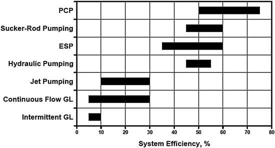
1.1.3.2SystemEfficiencies
Energyefficienciesofpresent-dayartificialliftmethodsareverydifferentas shownin Fig.1.3.Theoverallefficiencyofanartificialliftinstallationisfound fromthetotalenergyrequiredtooperatethesystemandthehydraulicpower spentonliftingthefluidstothesurface.Theefficiencyistheproductofthe individualefficienciesofthesystem’scomponents.Thedecisivepartofthe overallefficiencyisduetotheeffectivenessoftheliftingmechanism,e.g., theenergyefficiencyofthepumpused,butpowerlossesinthewellandonthe surfacecanalsohaveagreatimpactonthefinalfigure.Thebasicprerequisite forhightotalenergyefficiency,therefore,istheapplicationofahighlyefficientliftingmechanism.
Themostenergy-efficientdeviceavailableforartificialliftingistheprogressingcavitypumpthatcanbemorethan70%efficientinconverting mechanicalenergytohydraulicwork.Becausetheuseofprogressingcavity pumpsinoilwellsrequiresrelativelysimplesurfaceanddownholeinstallationswithlowlevelsofenergylossesinsystemcomponents,PCPsystemsarethemostefficientamongtheartificialliftmethods.Nowonderthat, whereverwellconditionsfallintheirapplicationranges,thenumberofPCP installationsisgrowingveryfast.
Nextintheline,asshownin Fig.1.3,aresucker-rodpumpingandESP installationswithmaximumsystemefficienciesofabout60%.Althoughsuckerrodandelectricsubmersiblepumpsalonecanhavequitehighenergyefficiencies,bothliftingmethodsareplaguedbyhighdownholelossesintheir powertransmissionsystem.Inadditiontotheselosses,freegasenteringthe