No part of this publication may be reproduced or transmi�ed in any form or by any means, electronic or mechanical, including photocopying, recording, or any information storage and retrieval system, without permission in writing from the publisher. Details on how to seek permission, further information about the Publisher’s permissions policies and our arrangements with organizations such as the Copyright Clearance Center and the Copyright Licensing Agency, can be found at our website: www.elsevier.com/permissions.
This book and the individual contributions contained in it are protected under copyright by the Publisher (other than as may be noted herein).
Notices
Knowledge and best practice in this field are constantly changing. As new research and experience broaden our understanding, changes in research methods, professional practices, or medical treatment may become necessary.
Practitioners and researchers must always rely on their own experience and knowledge in evaluating and using any information, methods, compounds, or experiments described herein. In using such information or methods they should be mindful of their own safety and the safety of others, including parties for whom they have a professional responsibility.
To the fullest extent of the law, neither the Publisher nor the authors, contributors, or editors, assume any liability for any injury and/or damage to persons or property as a ma�er of products liability, negligence or otherwise, or from any use or operation of any methods, products, instructions, or ideas contained in the material herein.
ISBN: 978-0-12-818868-2
For Information on all Elsevier publications visit our website at h�ps://www.elsevier.com/books-and-journals
Publisher: Charlo�e Cockle
Acquisitions Editor: Graham Nisbet
Editorial Project Manager: Mica Ella Ortega
Production Project Manager: Kamesh Ramajogi
Cover Designer: Christian J. Bilbow
Typeset by MPS Limited, Chennai, India
Dedication
Dedicated to the loving memory of my father, Mr YAHYA Gohari Darabkhani (1946–2021), who showed me how to live a simple life with passion and morality.
–Hamidreza Gohari Darabkhani
Dedicated to my wife Mrs Hamraz Sahebirashti, my daughter Tida, my mother Shanaz Mirjafari, and my father Mr Mohammadsaeid Varasteh.
–Hirbod Varasteh
Dedicated to my mother, Tahereh Salmanian (1956–2009).
–Bahamin Bazooyar
Preface
Clean and sustainable energy supply is one of the strategic needs of countries worldwide. One of the most important parts of energy is electricity, which has a great impact on the energy basket of every country. A large amount of the electricity is provided through conversion of fossil fuels in power plants. It is however vital to limit the emission of greenhouse gases (GHGs) from burning fossil fuels and this can be done by a combination of technologies including carbon capture, improving the efficiencies of power plants, and adapting the renewable energy sources to the power generation systems.
The United Kingdom hosted the 26th UN Climate Change Conference of the Parties (COP26) from 31st October to 13th November 2021 in Glasgow. The summit of COP26 brought parties together to accelerate action towards the goals of the UN Framework Convention and the Paris Agreement on Climate Change. One of the key objectives of the COP26 was the planning on how to achieve the global targets of net zero emissions by 2050. To reach this target, carbon capture and storage (CCS) technologies will be having a big share in removing carbon emissions from the energy sectors and industrial process. From the three main carbon capture technologies (i.e., precombustion, postcombustion, and oxyfuel combustion capture), oxyfuel combustion capture has a high potential to be implemented in both newly designed and retrofi�ed power plants. Oxyfuel combustion capture involves burning of the fuel with nearly pure oxygen instead of air and recycling some part of the flue gases back into the furnace/boiler to control the flame temperature. The majority of the capture technologies are designed for the atmospheric combustion of the solid fuels (e.g., coal, biomass). When
burning natural gas, particularly at elevated pressures, e.g., in gas turbine systems, oxyfuel combustion capture will become a superior option (oxyturbine CCS). The cycle engages recirculation of the flue gases to generate a high concentration of CO2 in the exhaust ready for simple capture and storage. This normally results in full CO2 capture and almost no NOx emission from these power plants. The membrane capture for gas-fired systems is another a�ractive option for gas turbine power plants. Selective recirculation of the flue gases through the CO2 selective polymeric membranes increases the concentration of CO2 in the flue gases to bring it close to the level of CO2 concentration in the exhaust of the solid fuel combustion to feed a solvent-based postcombustion capture unit.
This book presents Carbon Capture Technologies for Gas-TurbineBased Power Plants and explores current progress in oxyfuel combustion capture as one of the most capable technologies for carbon capture in power plants. The three major carbon capture technologies (precombustion, postcombustion, and oxyfuel combustion) and the membrane technology are explained in this book, and the pros and cons of each technology are compared with the oxyfuel combustion capture. This book investigates over 20 different oxycombustion turbine (oxyturbine) power cycles, identifying the main parameters with regard to their operation, process, and performance simulations, and energy and exergy analysis. The natural gas combined cycle (NGCC) power plant with postcombustion capture is used as the base-case scenario. One of the challenges of the oxyfuel combustion technology is the need to generate pure oxygen on site. Therefore, the oxygen production and air separation units (ASU) and CO2 compression and purification units (CPU) are explained in this book. The procedure for the design and the operational characteristics of a radial NOx-less oxyfuel gas turbine combustor are presented and the combustor CFD simulation and performance analysis of the heat exchanger network and turbomachinery are conducted. The book provides technoeconomic analysis, technology readiness level (TRL), sensitivity and risk analysis, levellised cost of energy (LCOE), and the stages of
development for oxycombustion turbine power plants. This book can be used to generate a road map for the development of future gas turbine-based power plants with full carbon capture capabilities using the experiences of the recently demonstrated cycles. The content of this book can support students, researchers, engineers, policymakers, and energy industry managers to plan the development and deployment of the future zero carbon and NOx free gas-fired power plants to help achieve the net zero targets in the energy industry.
Acknowledgment
This book was prepared through the research conducted at three eminent UK universities between 2018 and 2021. Prof. Hamidreza Gohari Darabkhani, Professor of low carbon and renewable energy systems from Staffordshire University, has been the projects’ academic lead and supervisor for the oxyturbine CCS research project and the Innovative UK funded microturbine renewable energy combustor (MiTREC) project. Dr. Hirbod Varasteh, lecturer in civil engineering at University of Derby, conducted the oxyturbine CCS research and the process simulation works. Dr. Bahamin Bazooyar, research associate at Cranfield University, conducted the oxyfuel combustion research, design, and CFD modeling. The authors would like to profess their sincere gratitude to all people, universities, and research projects that provided tools and support for the preparation and publication of this book. Staffordshire University is specially thanked for hosting the main research and providing Aspen Plus V12.2 and GasTurb 13 licenses for the oxyturbine process and performance simulations. University of Derby is acknowledged for the wise counsel and vision of the thermodynamic cycles. Cranfield University provided the license of Ansys 2021 R2 software. The computer simulations were mainly done using a supercomputer at Staffordshire University purchased from the budget of the MiTREC project. The MiTREC project resulted in the successful development of a micro gas turbine combustor for renewable biogas fuel in collaboration with an industry partner, Bladon Micro Turbines Ltd. The authors would also like to thank Mrs. Hamraz Sahebirashti for the proofreading of the book’s chapters.
All authors would like to thank their families who have indirectly supported them throughout their research journeys, resulting in the significant publications including this book, that will ultimately help society by introducing cleaner energy options.
An introduction to gas turbine systems
Abstract
Gas turbine cycles are being used extensively in both power and propulsion systems. The thermodynamic cycle that describes how a gas turbine is operating is called the Brayton Cycle. This heat engine extracts energy from fuel and air after pressurised combustion through the turbine unit. The world’s first industrial gas turbine operated in Swi�erland, in 1939, and commercial operation of the first gas turbine in the United States generated 3.5 MW electrical power in Oklahoma City in 1949. The combustion of fossil fuels in gas turbine systems generates greenhouse gases including CO2. To investigate oxyfuel combustion capture technology this chapter is aiming to explain the fundamental aspects of the gas turbine cycles.
Keywords
Gas turbine; greenhouse gases (GHG); heat engine; Brayton cycle
1.1 Introduction
Greenhouse gases (GHG) are the main reason for the increase in the global mean temperature and climate change. Carbon dioxide (CO2) from the combustion of fossil fuels is the principal GHG, and power plants and the energy sector are the main sources of CO2 emissions. With 73.2% of carbon emission from the energy sector, including industry, transport, building and agriculture, this sector is
considered as the main contributor to the global warming (Ourworldindata, 2020). The carbon budget is the cumulative amount of carbon dioxide emissions permi�ed over a period of time to keep the temperature rise within a certain temperature threshold. The carbon budget for the 2°C global temperature increase scenario has an upper limit on the cumulative CO2 that is in the range of 800–1400 GTCO2, and the carbon budget for 1.5°C scenario is in the range of 200–800 GtCO2 (IEAGHG, 2019).
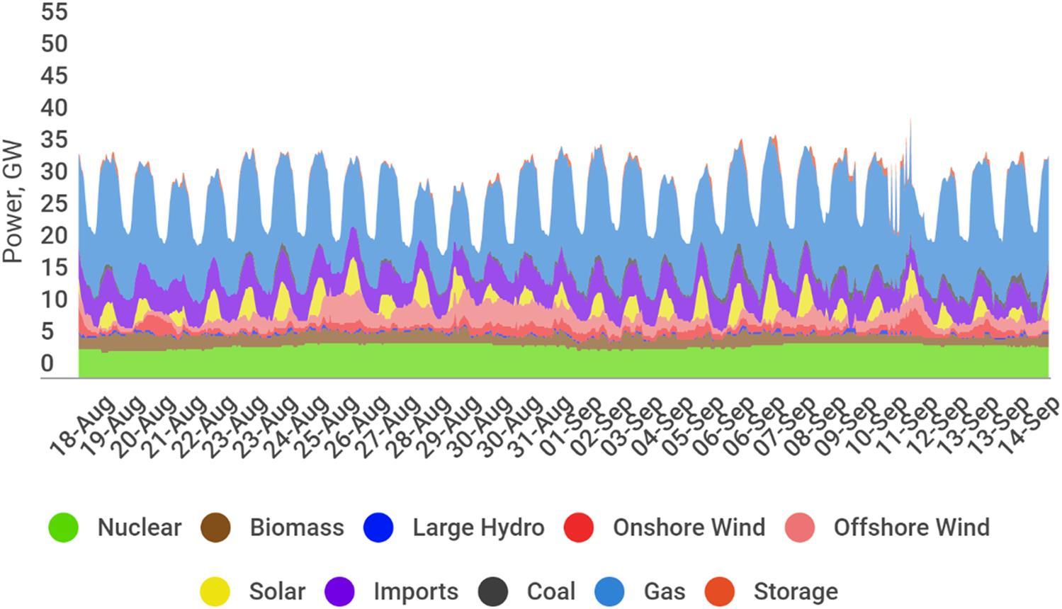
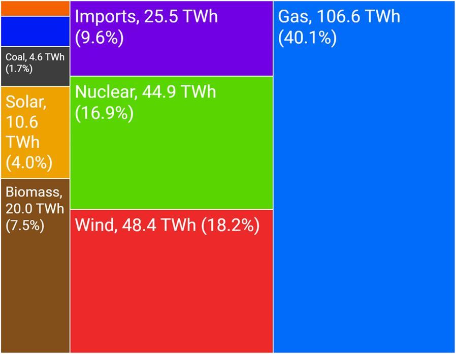
The avoidance and reduction of carbon dioxide emission from the energy sector is the main strategy to mitigate climate change. Gas turbine systems are widely used to generate electrical power and to balance the power demand and response to grid fluctuations. Fig. 1.1 shows the electricity generation in the UK for 28 days from 18 August 2021 to 14 September 2021. In one year period (from September 2020 to the end of August 2021) in the UK, over 40% of electricity was generated from gas combustion, mainly in gas turbine power plants and there was an overall combined emission of 236 gCO2/kWh in this 12 months in the UK (Fig. 1.2).
FIGURE 1.1 Power generation in the UK for 28 days from 18 August 2021 to 14 September 2021 (MyGridGB, 2021) Please see the online version to view the colour image of the figure.
FIGURE 1.2 Sources of electricity generation in the UK from September 2020 to the end of August 2021 (MyGridGB, 2021).
The increasing concern for climate change has led to global efforts to reduce carbon dioxide (CO2) in the atmosphere. It appears that by far the most significant contribution to the greenhouse effect stems from emissions of carbon dioxide. A large part of the CO2 emission is produced by combusting fossil fuels in conventional power plants and industrial processes (United State Environmental Protection Agency, 2018). Nonetheless, Global demand for fossil fuels are increasing. For instant natural gas (NG) demand is forecasted to increase by 2.5% a year for the next 10 years (IEAGHG, 2020).
The gas turbine power generation is more flexible in responding to electrical demand (Bazooyar and Darabkhani, 2020). However, conventional gas turbines burn fossil fuels and release a massive amount of CO2 equivalent emissions to the environment. The power generation from fossil fuels is likely to continue in the future to
respond the energy demand, and conventional power plants will produce 74% of energy in 2040 even under new policy scenario: oil, gas and coal will provide 27%, 24% and 23%, respectively, of energy demand in 2040 (Gonzalez-Salazar et al., 2018).
In order to meet the electricity demand as well as the CO2 mitigation targets, it is essential to increase the efficiency of fossilfuel-based energy conversion systems along with the implementation of carbon capture and storage (CCS) technologies. There are three carbon capture technologies: pre-combustion, postcombustion and oxy-fuel combustion capture. Oxy-fuel combustion is one of the promising carbon capture technologies that aim to provide zero NOx emission and pure CO2 streams ready for sequestration. The development of oxy-fuel combustion technologies can lead to high-efficiency clean energy power plants. The market opportunity for this technology is quite a�ractive, and the project’s dissemination in the energy industry is extensive. Despite postcombustion capture technology, oxy-fuel combustion capture systems don’t need a complicated carbon capture cycle at the back of power plant, but do need an air separation unit (ASU) in front of the cycle.
1.2 Introduction to the gas turbine technology
The idea of the gas turbine goes back a long time. John Wilkins (1614–72) used the motion of air that ascends a chimney to turn a rod (EAVES PSK, 1971), but the basic concept of power generation by gas turbine goes back to Barber in 1791 (Horlock and Bathie, 2004).
The gas turbine has been used extensively since 40 years ago in power generation and different industries including in transportation and in oil & gas industries. There are various types of gas turbine with different fuels such as natural gas, diesel fuel, and biofuels.
The first generation gas turbine has major problems with the efficiency penalty of the compressor. The, compressor was driven independently in the early designs of the gas turbine. Also, the turbine must be highly efficient to produce enough power to drive
the compressor and generate the required power network. One of the first gas turbines was developed by two French engineers, Armengaud and Lemae, in 1904; the power network was about 10 kW, and overall efficiency was approximately 3%. The first industrial gas turbine was invented by Brown Boveri in 1939; the network output was 4 MW. Frank Whi�le (1907–1996) developed the first turbojet gas turbine engine in 1930 with enough network power and high-speed jet for aircraft propulsion.
The heavy gas turbines have been developed to produce electrical power by combined cycle gas turbine with a bo�om cycle of the steam turbine (CCGT) (Horlock and Bathie, 2004). Gas turbine material technologies have been developed during the last 20 years. The cooling method of the blade and new coating materials let the turbines work at higher temperature, such as the NetPower cycle and CES cycle; in recent years, the development of composer pressure ratio support has increased turbine efficiency up to 60%.
Gas turbines convert the chemical energy of the fuel into either mechanical energy or kinetic energy. There are two types of gas turbines: (1) power generation gas turbines that convert the chemical energy of the fuel to shaft power to produce electricity and (2) gas turbines for aircraft which produce thrust for propulsion (Schobeiri and Meinhard, 2018).
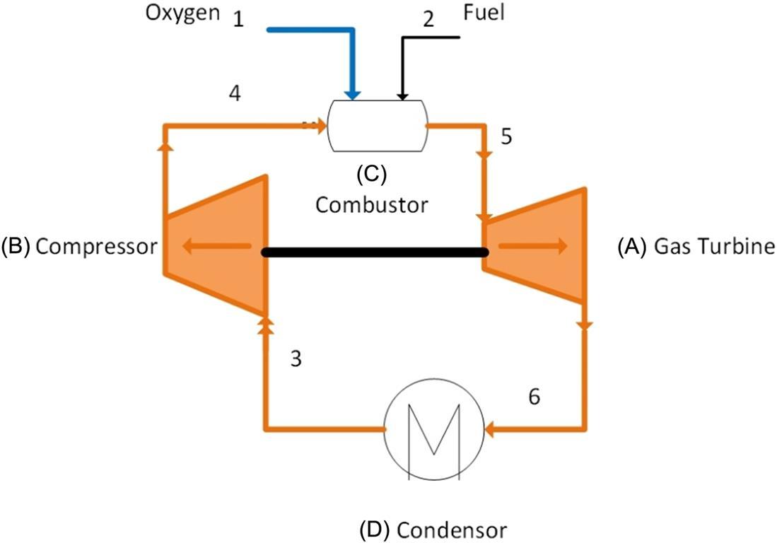
The main concept of gas turbine thermodynamics is receiving fuel energy at a high temperature at the combustor (C) to produce work at the gas turbine (A) and release the remaining energy to heat sink with the low temperature at the condenser (D), as shown in Fig. 1.3.
FIGURE 1.3 Typical gas turbine cycle.
The power plants need to produce a network with minimum fuel consumption. However, the capital cost and operational cost need to be balanced to produce electricity with a lower cost (cost/kW h 1) (Horlock and Bathie, 2004). In recent years, new gas turbine technologies have been developed to reduce greenhouse gas emissions. To this end, the combustor section of these turbine are designed to work with renewable fuels including biogas (Bazooyar and Darabkhani, 2021), hydrogen (Bazooyar and Darabkhani, 2019) etc.
1.3 Categories of gas turbines
There are seven categories for the simple cycle gas turbines as below:
1. Heavy duty gas turbines:
The power generation units are larger, normaly between 30 and 480 MW, and the efficiencies are between 30% and 46%.
GE’s heavy duty and aeroderivitive gas turbines feature an
output range from 34 MW to 571 MW. Heavy duty gas turbines are used generally for power generation in big power plants, and they are capable of burning variety of fuels, ranging from light petroleum to heavy residuals and from natural gas to various process gases.
2. Aircraft-derivative (Aeroderivitive) gas turbines: These are aircraft gas turbines, which have replaced fans with a turbine at the exhaust, and power is between 2.5 and 50 MW with efficiencies of 35%–45% (Boyce, 2011). They respond faster and are lighter with up to 45% efficiency. The turbines are also popular due to their fuel flexibility (Nascimento et al., 2013). Aeroderivative gas turbines are designed specifically for air use such as airplanes, however, they are also used in land applications for smaller power in more compact and lighter units with higher efficiencies and pressure ratios.
3. Industrial gas turbines:
These types of gas turbines are used for medium-range power and are usually rated between 5 and 15 MW for the compressor of petrochemical plants with low efficiencies of about 30% (Boyce, 2011).
One type is the Rolls-Royce Industrial Trent family gas turbine. This turbine produces high power with variable speed which is suitable for natural gas liquefaction, gas transportation, and gas injection for oil recovery. ALSTOM, General Electric, and Siemens-Westinghouse are the main manufactures of the large single-shaft gas turbines with greater than 250 MW per unit.
Industrial gas turbines can be used for different sectors because of their flexibility. These turbines can be used for mechanical drive systems, chemical industries, transportations, pump drives and power generation (ElSayed, 2017).
4. Small gas turbine:
The radial turbines with centrifugal compressors produce power between 0.5 and 2.5 MW with a very low efficiency of
p y y 15%–25% (Boyce, 2011). They can be used for combined heat & power generation in GT CHP plants, in oil and gas recovery and for autonomous heat and power supply.
5. Microturbines (Micro Gas Turbine):
These gas turbines can produce power from 1 kW up to 300 kW (in some notes up to 500 kW), and they are used for industries and domestic clients (Bazooyar and Darabkhani, 2019). These gas turbines are normaly open cycle gas turbines with different features, such as high-speed operation, compact size, variable speed, low maintenance, easy installation and simple operability (Marco Antônio, 2005). Micro gas turbines have a particular application in decentralised heat and power generation for domestic application (Bazooyar and Darabkhani, 2020).
6. Gas turbines at sea:
The first successful boat with a gas turbine was the Motor Gun Boat in 1947, and the first fast patrol boat with a gas turbine was fabricated by Rolls Royce Proteus. General electric fabricated LM services for US Navy Burke Destroyer, Italian Lupo Frigate, and AEGIS Cruiser. The advantages of the gas turbine for marine industries are compact size, low noise and high power density (El-Sayed, 2017).
7. Gas turbines at the ground:
US tank M1A1 Abram has used the AlliedSignal Lycoming AGT1500 gas turbine. Also, a gas turbine engine is used for Union Pacific in the United States to operate locomotives. The gas turbine produces electricity to the electric power motors of the locomotive (Union Pacific, 2020). Lightweight, reliability and compactness are the advantages of a gas turbine for road transportation. The gas turbine engine has a vibration-free operation compared with the reciprocating engine, and it has a lower maintenance cost with low lubricating oil. The gas turbine engine can consume various fuels without redesigning combustion; furthermore, the micro gas turbine engine has lower carbon emissions and is more environmentally friendly. Low efficiency during part-
y y y g p load and idle conditions is the gas turbine engine disadvantage for road transportation. Another disadvantage is the required time to reach full load from idle; the acceleration time depends on gas turbine characteristics (Cunha and Kyprianidis, 2012). The project to fabricate a snow plough with a PT6 turboshaft gas turbine began in the early 1960s in collaboration with Pra� & Whitney Engines and the Department of Highways in British Columbia, Canada. The powerful snow plough was required to combat heavy snowfall, and it needed to be mobile enough to operate on the mountainous roads. The snow plough was used in British Columbia road for years (PT6Nation, 2018).
Table 1.1 shows a comparison of the industrial gas turbine with an aero-derivation gas turbine.
Table 1.1
Comparison of an industrial gas turbine with an aeroderivative gas turbine.
Observation
Industrial compared to aeroderivative
Shaft speed Slower
Air flow Higher
Maintenance intervals
Maintenance lay-down
Efficiency
1.4 Type of gas turbine
One classifications for gas turbines is based on the number of spools. The gas turbine can be single-spool/shaft, two-spool (dual-shaft) or