BondedJointsand RepairstoComposite AirframeStructures
ChunH.Wang
CongN.Duong
AcademicPressisanimprintofElsevier
125LondonWall,London,EC2Y5AS,UK
525BStreet,Suite1800,SanDiego,CA92101-4495,USA
225WymanStreet,Waltham,MA02451,USA
TheBoulevard,LangfordLane,Kidlington,OxfordOX51GB,UK
Copyright # 2016ElsevierInc.Allrightsreserved.
Nopartofthispublicationmaybereproducedortransmittedinanyformorbyanymeans, electronicormechanical,includingphotocopying,recording,oranyinformationstorage andretrievalsystem,withoutpermissioninwritingfromthepublisher.Detailsonhowto seekpermission,furtherinformationaboutthePublisher’spermissionspoliciesandour arrangementswithorganizationssuchastheCopyrightClearanceCenterandtheCopyright LicensingAgency,canbefoundatourwebsite: www.elsevier.com/permissions.
Thisbookandtheindividualcontributionscontainedinitareprotectedundercopyright bythePublisher(otherthanasmaybenotedherein).
Notices
Knowledgeandbestpracticeinthisfieldareconstantlychanging.Asnewresearchand experiencebroadenourunderstanding,changesinresearchmethods,professionalpractices, ormedicaltreatmentmaybecomenecessary.
Practitionersandresearchersmustalwaysrelyontheirownexperienceandknowledgein evaluatingandusinganyinformation,methods,compounds,orexperimentsdescribed herein.Inusingsuchinformationormethodstheyshouldbemindfuloftheirownsafety andthesafetyofothers,includingpartiesforwhomtheyhaveaprofessionalresponsibility.
Tothefullestextentofthelaw,neitherthePublishernortheauthors,contributors,oreditors, assumeanyliabilityforanyinjuryand/ordamagetopersonsorpropertyasamatterof productsliability,negligenceorotherwise,orfromanyuseoroperationofanymethods, products,instructions,orideascontainedinthematerialherein.
BritishLibraryCataloguinginPublicationData
AcataloguerecordforthisbookisavailablefromtheBritishLibrary LibraryofCongressCataloging-in-PublicationData
AcatalogrecordforthisbookisavailablefromtheLibraryofCongress
ForinformationonallAcademicPresspublications visitourwebsiteat http://store.elsevier.com/
ISBN:978-0-12-417153-4
Preface
Advancedfiber-reinforcedpolymercompositesarenowwidelyusedinaircraftconstruction,forbothprimaryandsecondarystructuralapplications.Forinstance,the constructionsofboththeAirbus350andBoeing787aircraftemployadvancedfiber compositesasmorethan50%oftotalweight.Thisdemandsnewdevelopmentsin designandanalysismethodologies,applicationprocesses,andnondestructive inspectiontechniquesforbondedjointsandbondedrepairs.Theaimofthisbook isthereforetoprovideacomprehensivecoverageofrecentadvancesthatarerelevant tosafety-criticalcompositestructures.Inparticular,thisbookfocusesonthemajor challengesfacedduringrepairsofcompositestructures,incomparisontoconventionalmetalliccomponentsthatarethesubjectofrelatedbooks(Bakeretal., 2002;DuongandWang,2007).
Intendedtobeusefultopracticingengineers,designers,andresearchersinthe field,thisbookgrewoutofrecentresearchthattheauthorsconductedattheRoyal MelbourneInstituteofTechnology(RMIT),theDefenceScienceandTechnology Organisation(DSTO,Australia),andtheBoeingCompanyoverthepast10years. Thetopicsaddressedhereinaredevelopedtotheextentthatthepresentationissufficientlyself-explanatory.Hence,itcouldserveasastate-of-the-artreferenceguide topractitioners,engineers,andscientistswhoareinterestedinfurtherresearchinthis field.Thisbookfocusesonthedesignandanalysismethodologiesandapplication processesofdoublerandscarfrepairsofcompositeairframestructures,alongwith theirrepresentativejoints.
Theauthorshaveorganizedthebookinto10chapters. Chapter1 presentsanoverviewofthecompositerepairtechnology,withabriefsummaryofthekeyconcepts andanalysismethodologies,certificationrequirements,andscopeofapplications. Chapter2 outlinesrelevantfailurecriteriaforadhesivesandcomposites,followed byadescriptionofvariousanalyticalmethodsfordoublerjointsandscarfjoints in Chapters3 and 4,respectively.Toaddressthemajorchallengeofcertifyingadhesivelybondedrepairstoprimaryandsafety-criticalstructures, Chapter5 outlinesthe analyticalandnumericalmethodsforquantifyingtheeffectsofabnormalitiessuchas disbondonthestrengthofadoublerjoint.Similarconsiderationofdamagetolerance forascarfjointisgivenin Chapter6.Eventhoughdiscussionsdelineatedin Chapters 5 and 6 aremostlylimitedtobondedjoints,theydemonstratetheessentialconcept neededfordamagetoleranceanalysisofbondedrepairs.Incontrast,thedesignand analysisofexternalrepairsandinternalrepairstomeetstaticstrengthrequirements aredescribedrespectivelyin Chapters7 and 8 Chapter9 thendiscussestheaspectof themanufacturingprocessinbondedrepairs.Finally,nondestructivetechniquesfor inspectionofthestructuralintegrityoftherepairsarebrieflyreviewedin Chapter10.
Theauthorswouldliketoexpresstheirthankstoanumberofcolleagues. Between1995and2009Chun-HuiWangspent14yearsworkingattheDefenceScienceandTechnologyOrganisation(DSTO),whereheenjoyedexcellentmentoring byDrsFrancisRose,AlanBaker,andRichardChester,withwhomhehascoauthored
manyscientificpublicationscitedinthisbook.Duringthisperiodoftime,hecontributedsignificantlytothedevelopmentnewmethodologiesforthedesignofcompositerepairs,aninsituquantitativeimagingmethodforstructuralhealth monitoring,andfatiguelifeprediction.Manyofhisresearchresultshavetranslated intopracticaloutcomesthroughDefencestandards,commercialsoftwares,andpatents.HeisindebtedtomanyofhiscolleaguesatDefenceScienceandTechnology Organisation(DSTO)fortheirwonderfulfriendship,contributions,andsupport.He wouldalsoliketothankDrsAndrewRider,AlexHarman,PaulChang,PaulCallus, andJohnWangascoauthorsofmanyofresearchpapersthatformthebasisof thisbook.
Since1999,thesecondauthorhashadseveralopportunitiestoworkonthedevelopmentsofdesignandanalysismethodologiesforbondedrepairapplications.First, heworkedonmetallicairframestructuresthroughtheCompositeRepairofAircraft Structures(CRAS)programfundedbytheUnitedStatesAirForceResearchLaboratory(AFRL).Subsequently,heworkedoncompositeairframestructuresthrough Boeinginternalresearchprograms.Heisthereforeindebtedtohiscolleaguesfor theircontributionstoandsupportofthiscompositerepairresearch.Inparticular, hewouldliketothankDrsJohnZ.Lin,JohnHart-Smith,JinYu,JohnTracy,and Mr.RustyKeller,aswellasthemanagementoftheBoeingCompany.Last,but nottheleast,bothauthorsaregratefultotheirfamiliesfortheirunwaveringlove, encouragement,patience,andsupportwhilethisbookwasbeingwritten. September2015
REFERENCES
Baker,A.A.,Rose,L.R.F.,Jones,R.,2002.Adcvancesinthebondedcompositerepairof metallicaircraftstructure.Amsterdam:Elsevier. Duong,C.N.,Wang,C.H.,2007.CompositeRepair:TheoryandDesign.Oxford:Elsevier.463.
Introductionandoverview 1
1.1 AIMOFBOOK
Advancedfiber-reinforcedpolymercompositesarenowwidelyusedinaircraftconstruction,forbothprimaryandsecondarystructuralapplications.Forinstance,the Airbus350andBoeing787aircraftemploymorethan50%weightofadvancedfiber compositesintheconstruction.Thisgreatuseofcompositesinsafety-criticalsystemscanbeattributedtomanyadvantagesoffiber-reinforcedcomposites,suchas higherspecificstrengthandstiffness,higherimmunitytocostlystructuraldegradation,suchascorrosiondamageandfatiguecrackingthatplaguealuminumandother lightalloyscommonlyfoundinoldgenerationsofaircraft.Beyondaerospaceapplications,suchasautomotivevehicles,windturbines,offshoreoilandgasproduction equipment,andcivilinfrastructures,therehasalsobeenarapidriseintheuseoffiber compositesasakeylightweightingtechnologytoreducefuelconsumptionandto improveenergyefficiency.
Theaimofthisbookistoprovideacomprehensivecoverageofdesign,analyses, applicationprocesses,andnondestructiveevaluationofadhesivelybondedrepairsof compositestructuresofcriticalimportancetooperationalsafety.Inparticular,this bookfocusesonthemajordifferencesbetweenrepairsofcompositestructures andconventionalmetalliccomponents,withthelatterbeingthesubjectofrelated books(Bakeretal.,2002;DuongandWang,2007).Inthecaseofconventional metallicstructure,repairsgenerallyhaveoneofthreeobjectives:fatigueenhancement,crackpatching,andcorrosionrepair(DuongandWang,2007).Bycontrast, structuresmadeofadvancedcompositestructuresdonotsufferfatigueorcorrosion damage,butaremoresusceptibletoin-servicedamage,forexample,bymechanical impact(hailstones,birdstrikes,tooldrops,andrunwaydebris),lighteningstrikes, andoverheating.Thisisduetocomposites’relativelylow-matrixdominatedproperties,suchasthrough-thicknessstrengthandtoughness.
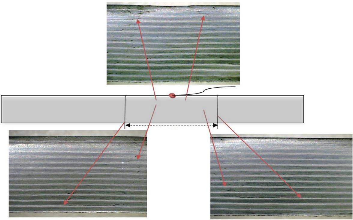
Someexamplesofimpact-induceddamageincompositelaminatesareshownin Figure1.1,illustratingthecomplexnatureofinterplyandintraplycrackingthat extendslaterallyfromthepointofimpact.Itisworthnotingthatthedelamination damagetendstooccurthroughouttheentirethicknessofcompositelaminates,for boththinandthicksectionstructures.Thistypeofmatrix-dominateddamagecan outspreadinthebackfaceregion,withmuchofthedamagebeinghiddenfromexaminationoftheexternalsurface.Thematrixdamageintheformofdelaminationcan significantlyreducetheflexuralstiffnessandhencethecompressivestrength.Ifthe
Examplesofimpactdamageinfibercomposites.(a)MorphednaturalandUVlights imageof21-plyCytecIM7/977-3subjected18Jimpact.(b)VTM264laminate(56plies [45/0/ 45/90]7S)subjectedto32Jimpact.
damageisofsufficientsize,exceedingtheallowabledamagelimitpertinenttothe designload,delaminationmaypropagateundertheappliedmechanicalloading,furtherreducingtheresidualcompressivestrength.Thereforetoensurecontinuing safety,itiscriticallyimportanttorepairdamageoncedetectedandreturnthestructuralstiffnessandstrengthtotheoriginaldesignlevel(FAA,2010).
Thisbookisintendedtobeusefultopracticingengineers,designers,and researchersinthefield,withtheprimaryfocusonthedesign/analysismethodologies andapplicationprocesses.Thisfirstchapterpresentsanoverviewofthecomposite repairtechnology,withabriefsummaryofthekeyconceptsandanalysismethodologies,certificationrequirements,andscopeofapplications. Chapter2 outlinesrelevant failurecriteriaforadhesiveandcomposites,followedbyadescriptionofvariousanalyticalmethodsforanalyzingdoublerjointsandscarfjointsin Chapters3 and 4, respectively.Toaddressthemajorchallengeofcertifyingadhesivelybondedrepairs toprimaryandsafety-criticalstructures, Chapter5 outlinestheanalyticalandnumericalmethodsforquantifyingtheeffectsofabnormalitysuchasdisbondonthestrength ofadoublerjoint.Similardamagetolerantconsiderationforascarfjointisgivenin Chapter6.Eventhoughdiscussionsdelineatedin Chapters5 and 6 aremostlylimited tobondedjoints,theydemonstratetheessentialconceptneededfordamagetolerance
(a)
(b)
The point of impact
37.13 mm
FIGURE1.1
analysisofbondedrepairs.Incontrast,thedesignandanalysisofdoublerrepairsand internal(scarfandstepped)repairstomeetstaticstrengthrequirementsaredescribed respectivelyin Chapters7 and 8. Chapter9 thendiscussestheaspectofmanufacturing processinbondedrepairs.Finally,nondestructivetechniquesforinspectionofthe structuralintegrityoftherepairsarebrieflyreviewedin Chapter10.
1.2 CRITICALITYOFSTRUCTUREANDDAMAGE
Aircraftstructuresaregenerallyclassifiedasfollowsintermsofcriticalityofthe structure:
•criticalstructure,whoseintegrityisessentialinmaintainingtheoverallflight safetyoftheaircraft(e.g.,principalstructuralelementsintransportcategory aircraft);
•primarystructurecarriesflight,ground,orpressurizationloads,andwhosefailure wouldreducetheaircraft’sstructuralintegrity;
•secondarystructurethat,ifitwastofail,wouldaffecttheoperationoftheaircraft butnotleadtoitsloss;and
•tertiarystructure,inwhichfailurewouldnotsignificantlyaffectoperationofthe aircraft.
Inspection,damageassessment,andrepairrequirementsdiffersignificantlybetween theseclassifications.However,evenwithinasinglecomponent,theallowabledamagetypeandsize(andconsequentlyacceptablerepairactions)willvaryaccordingto thecriticalityofthedamagedregion.Theoriginalequipmentmanufacturer(OEM) generallyzonesanaircraftcomponentintermsoftheseregions,andspecifiesrepair limitsandthepertinentrepairproceduresinthestructuralrepairmanual(SRM). DamagesoutsidethescopeoftheSRM,particularlytocriticalregionsofprimary structure,requireengineeringdesigndispositionandapprovalbytheOEM(orits delegate);thisbookdescribessomenewdesignoptionsdemonstratedbyrecent researchresults.
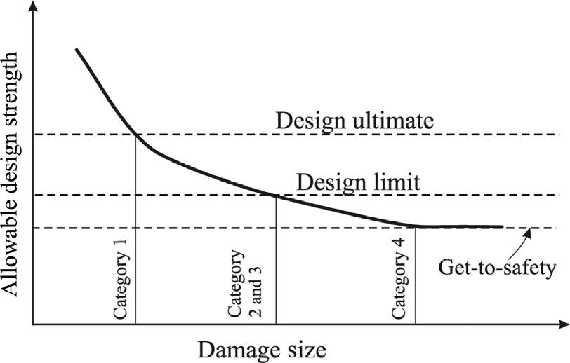
Foreignobjectimpactisusuallythemaintypeofdamageconcerningcomposite aircraftstructures.Toensurecontinuingairworthiness,itisnecessarytoidentify damageseverityanddetectabilityaspartoftheongoingmaintenanceprocess.Currentairworthinessregulations(FAA,2010)classifyvariousdamagetypesintofive categories,asindicatedin Figure1.2 thatillustratestherelationshipbetweendesign strengthanddamagesize:
• Category1:Allowabledamageorallowablemanufacturingdefectsthatdonot degradestructuralintegrity,andhencemaygoundetectedbyscheduled inspections.Structurescontainingthistypeofdamagearecapableofsustaining theultimateloadforthelifeoftheaircraftstructure.Someexamplesinclude barelyvisibleimpactdamage(BVID),smalldelamination,porosity,small scratches,andsoforth.Norepairsareneeded.
FIGURE1.2
Allowablestrengthversusdamagesize.
• Category2:Damagethatcanbereliablydetectedatscheduledinspection intervals.Thistypeofdamageshouldnotgrowor,ifsloworarrestedgrowth occurs,theresidualstrengthofthedamagedstructureduringtheinspection internalissufficientlyabovethelimitloadcapability.Someexamplesinclude visibleimpactdamage,deepgougesordebonding,andmajorlocaloverheating damage.Repairsareneededtorestorethedesignultimateloadcapability.
• Category3:Damagethatcanbereadilydetected,withinafewflights,by operationsormaintenancepersonnelwithoutspecialskillsincomposite inspection.Thestructurecanstillmaintainlimitornearlimitloadcapability. Repairsarerequiredimmediatelytorestoredesignultimateloadcapability.
• Category4:Discretesourcedamagethatwillreducethestructuralstrengthto belowthedesignlimitloadsuchthatflightmaneuversbecomelimited(i.e., structurecanmaintainsafeflightatreducedlevels).Examplesincluderotor burst,birdstrikes,tireburst,andseverein-flighthail.Repairsareneeded immediatelyafterflight.
• Category5:Severedamageoutsidedesignbutisself-evidentandknownto operations,suchasanomalousgroundcollisionwithservicevehicles,flight overloadconditions,abnormallyhardlandings,andsoforth.Immediaterepairis required.
Analyticalmethodsforassessingtheresidualstrengthofdamagedcompositecomponentsareneededtoensurethatonlynecessarilyrequiredrepairsareundertaken. Essentially,oneofthefollowingdecisionsmustbemade:
•Norepairaction—damageisnegligible.
•Onlyneededcorrectioniscosmeticorsealingrepairbecausedamageisminor.
•Structuralrepairisrequired(iffeasible)becausestrengthisreducedbelowultimate designallowable,orhasthepotentialtobereducedinsubsequentservice.
•Replacementisrequiredasrepairisnoteconomicallyortechnicallyfeasibleand componentmustbereplaced.
7 1.3 Typesofcompositerepairsandcertificationcriteria
ForBVID,quitelargeareasofdamage(typically25mmdiameter)canbetolerated foroldergenerationcarbon/epoxysystems(andbrittlehigh-temperaturesystems) withoutfailuresoccurringbelowtheultimatedesignstrainallowable,generally around5000microstrainforquasi-isotropiclaminatesmadeofunidirectional(tape) lamina.Recently,advancedcomputationalmodelingtechniqueshavebeenshownto beabletoaccuratelypredicttheresidualstrengthofcompositelaminatescontaining holesofvarioussizesandshapes(Wangetal.,2011a;Ridhaetal.,2014).Thus,the residualstrengthassessmentofastructurefollowingimpactdamagecanbeperformedsimilarlybyusingtheseadvancedcomputationalmethods.
FatiguestudieshavealsoshownthatBVIDwillnotgrowunderrealisticcyclic strainlevelsfortypicalcarbon/epoxylaminates.Thisisanimportantpointbecause BVIDwilloftennotbedetecteduntila100%nondestructiveinspectionisundertaken.Eventhoughthereisapossibilityofdamagegrowthandresidualstrengthdegradationunderhygrothermalcyclingconditions,thisappearstobeaseriousconcern onlyunderseverecyclingconditions.Thispossiblycatastrophicflawgrowthunder severehygrothermalcyclingmayresultfromexpansionofentrappedmoisturedueto freezingorsteamformationonheatingduringsupersonicflight.
Forsafety-criticalstructures,coupons,structuraldetails,elements,andsubcomponentsarerequiredtobetestedunderfatigueloadingtodeterminethesensitivityof structuretodamagegrowthandtodemonstratetheircompliancewitheithernogrowthorslow-growthrequirements.Thisistoensurethatadamagedstructure shouldnotbeexposedtoanexcessiveperiodoftimewhenitsresidualstrengthis lessthantheultimate.Oncethedamage(greaterthantheallowabledamagesize undercategory1)isdetected,thecomponentiseitherrepairedtorestoreultimate loadcapabilityorreplaced.
1.3 TYPESOFCOMPOSITEREPAIRSANDCERTIFICATION CRITERIA
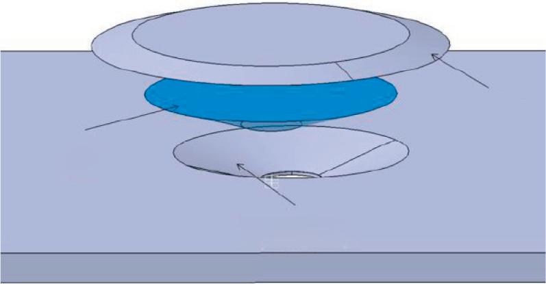
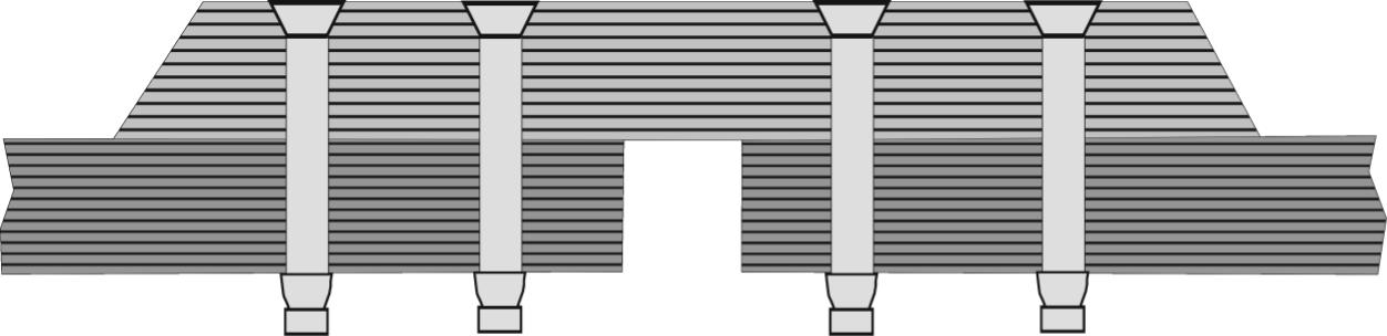
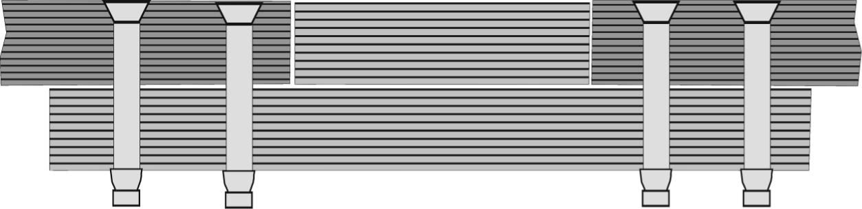
Structuralrepairscanbeperformedbymechanicalfastening,adhesivebonding,and hybridfasteningandbonding.Thedamagedmaterialisfirstcutoutasastraightsidedholeonwhichanexternaldoublerisattached,referringto Figure1.3a,orsculpturedtoformascarfofshallowangletoaccommodateascarfpatch,referringto Figure1.3b.Therepairpatchcanbethenattachedusingmechanicalfastenersor adhesivebonding.Cross-sectionalviewsoftheresultingrepairsareshownin Figures1.4 and 1.5,respectively.Whilethemajorintentofinternalrepairistoensure thattherepairedcomponentconformstotheexternalshapeofthestructure, alow-profiledoublerisacceptableinthemajorityofaircraftapplications.
Apartfromthestructuralsafetyconsiderations,repairsarerequiredtomeetother importantfunctionalrequirements,suchaslighteningstrikeprotection,radarsignature,aerodynamicperformance,andaesthetics.Inthiscontext,aninternalrepair, suchasthoseillustratedin Figures1.4b,c and 1.5b,c,isincreasinglythepreferred
Structuralrepairs:(a)externaldoublerrepairand(b)scarfrepair.
choiceofrepairs.Forexample,repairsthatprotrudeintotheairfieldnotonlyaddto theaerodynamicdragbutalsoadverselyaffecttheresalevaluesofpassengeraircraft.
Historically,adhesivelybondedrepairconceptsanddesignmethodologieshave beendevelopedtoaddresssecondarystructures,withoutconsideringsomeofthekey designrequirements(Wangetal.,2011a,2015;Gohetal.,2013)facedbysafetycriticalstructures.Forexample,existingdesignmethodologies(Wangand Gunnion,2008a,b)forinternal(scarf)repairsarecommonlybasedonanalyzing thepristinejointsasillustratedin Figure1.5c.Inotherwords,theultimateloadcarryingcapacityoftherepairiscalculatedwithoutconsideringanydisbondand delamination.Theplanformofthescarfrepairdependsonthelaminatelayup(which affectstheorthotropyofthecomposite)andtheappliedloads(WangandGunnion, 2008a,b,2009).Thisdesignmethodologyofanalyzingthepristinejointsandrepairs, however,isnotsuitableforsafety-criticalaircraftstructures,becauserecentairworthinessregulations(FAA,2005)requirethattherepairedstructurecanrestorethe damagetoleranceandfatiguedurabilityoftheoriginalstructure.Themajordesign requirementsinclude:
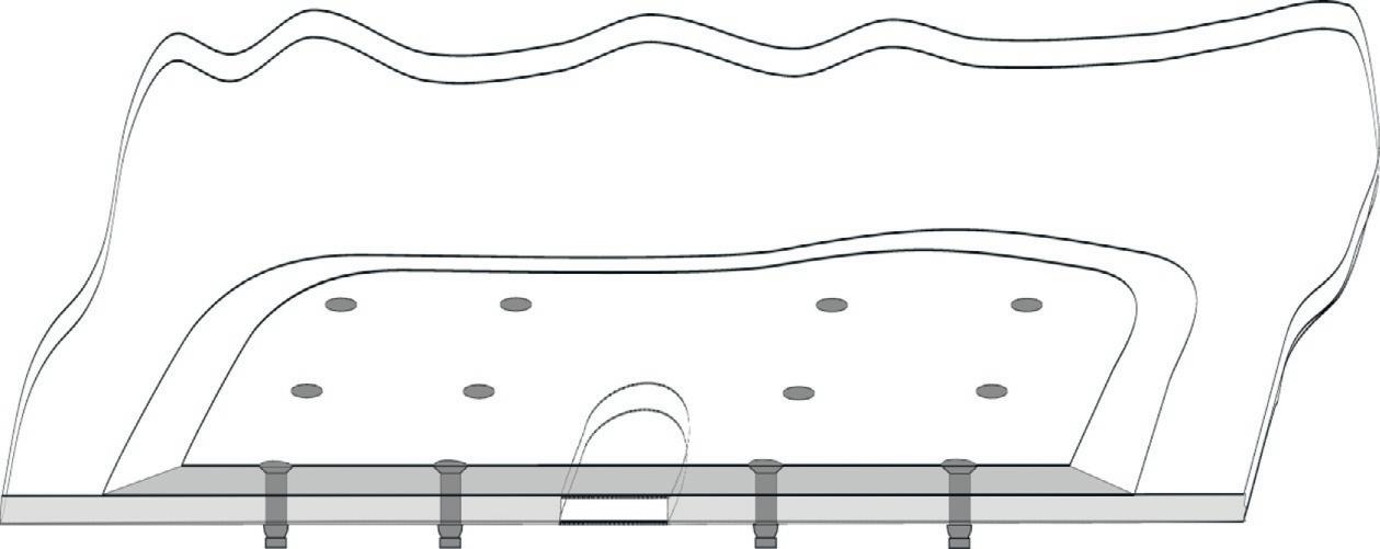
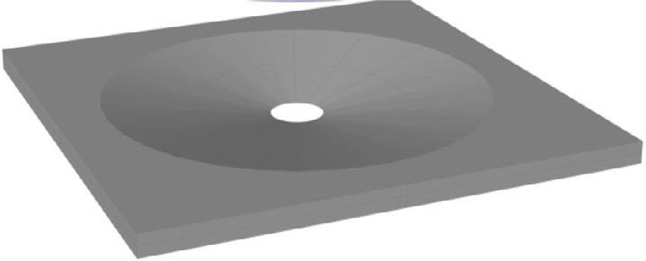
•Thescarfedstructure,withoutrepair,asillustratedin Figure1.6a,mustbeableto sustainthedesignlimitload(Wangetal.,2011a).Thisrequirementstemsfrom
(a)
(b)
Scarf repair patch
Doubler
Scarfed aircraft skin
FIGURE1.3
FIGURE1.4
Cross-sectionalviewsofmechanicallyfastenedrepairs:(a)externaldoublerboltedrepair (smalldamage),(b)internalboltedrepair(largedamage),(c)internalmultistepboltedrepair, and(d)internalscarfboltedrepair.
thecurrentlackofnondestructiveinspectiontechniquesthatcandetectweak bonds(Adams,2011).
•Therepairedstructuremustbeabletocarrythedesignultimateloadeveninthe presenceofallowabledamagesuchasdisbondorimpactdamage,asillustratedin Figure1.6b,andcanreachthefatigueenduranceoftheoriginalstructure.
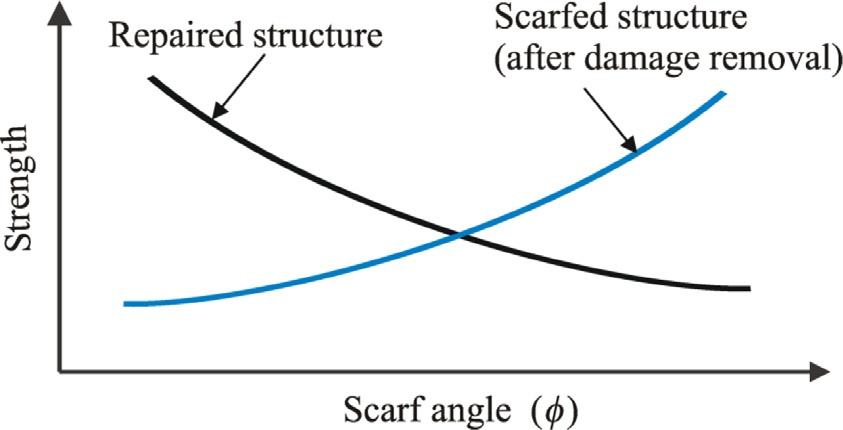
Astheangleofscarfdecreases,theresidualstrengthofacompositestructurecontainingascarfedholedecreases(duetohigherstressconcentration)whilethebonded strengthofascarfjointincreases,referringto Figure1.7.Scarfrepairdesigns,therefore,mustbalancebetweentwocontradictingrequirements:shallowtaperangleis neededtomeettheultimatestrength,whichistypically50%abovethedesignlimit
(c)
(d)
(a)
(b)
FIGURE1.5
Cross-sectionalviewsofadhesivelybondedrepairs:(a)externaldoublerbondedrepair, (b)internalmultistepbondedrepair,(c)internalscarfbondedrepair,and(d)doublerscarfrepair.
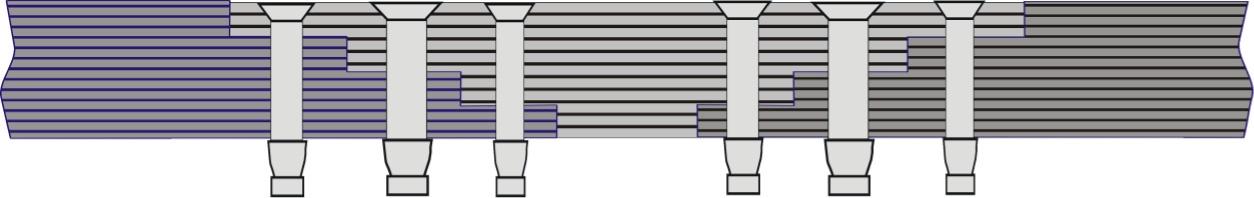
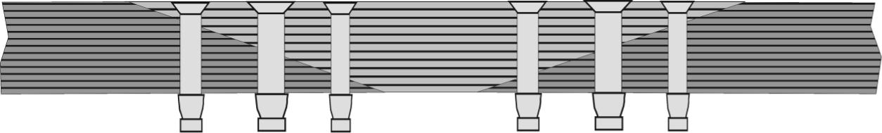
FIGURE1.6
(a)Scarfedcompositeand(b)scarfjointcontainingadisbond(Gohetal.,2013).
FIGURE1.7
Effectsofscarfangleonresidualstrengthandrepairstrength.
(b) (c) (a)
(a)
(b)
Flaw
load,whereassteeptaperisnecessarytoensuretheresidualstrengthtomeetthe designlimit.Inaddition,bondlineflaws(Wangetal.,2011b)andexternalimpact damage(HarmanandWang,2007)mustalsobeconsideredinthedesignofstructuralrepairsforsafety-criticalstructures.
1.4 OVERVIEWOFREPAIRDESIGNANDANALYSISPROCESS
Theanalysisprocessforrepairofdamagetostructureisdividedintothreephases:
(a) Assessthestructuralsignificanceofdamageonsystemsafety.
(b) Evaluatetheresidualstrengthofanunrepairedstructurewithacleanupdamage againsttherequirementofmeetingdesignlimitload.
(c) Determinethenecessaryrepairparameters(size,shape,andthicknessofa doublerrepair,orsize,shape,andtaperingangleofascarfrepair).
Phase(c)abovenormallyrequiresthefollowingthreeanalysissteps:
(i) Loadattractionanalysis:Todeterminethelocalincreaseofstressorstrainin theskinjustoutsidethepatchduetothelocalincreaseinoverallstiffnessof therepair.Thislocalstiffnessincreasecausesloadfromthesurrounding structuretobeattractedtotherepairlocation.Theskinstressconcentration atthedamagecutoutedge(aftertherepair)andthepatchstressesarealso affectedbytheloadattraction.
(ii) Bondstrengthanalysis:Todeterminethemaximumstressorstraininthe adhesiveofabondedrepair.Repairparametershavesignificantinfluenceson bondstrength.Theadhesivestressorstrainnormallypeaksattheedgesof repairpatchanddamagecutout,andplyterminationsinascarfrepair(Wang andGunnion,2008a).
(iii) Damagetoleranceanddurabilityanalysisofrepairs:Therepairs,bothdoubler andscarf,needtosustainthedesignultimateloadinthepresenceofdetectable flawsinthebondlineoranimpactdamage.Inaddition,anyacceptable manufacturingflawmustbedemonstratedtomeetano-growthrequirement underafatigueloadinguntiltheendoftheaircraftservicelife.
However,noteveryrepairtyperequiresallthreeoftheaboveanalysissteps.For example,asinternalrepairssuchasscarforsteppedrepairsnormallyinvolvea ply-by-plyreplacementofthedamagedpliesthatresultinnooverallstiffness increaseintherepairarea,aloadattractionanalysismaynotbeneededinthiscase.
1.5 EFFECTOFLOADATTRACTIONINPATCHDESIGN
Asmentionedin Section1.4,whentheoverallstiffnessoftherepairincreases,load fromthesurroundingstructureisattractedtotherepairlocation,resultinginalocal increaseofstressorstrainintheskinoutsidethepatchaswellastheadhesivestress
FIGURE1.8
Effectofloadattraction.Flowofloadlinesintopatchedregion.
orstrain,eventhoughstressorstrainintheskinunderneaththepatchwillbereduced. Thiseffectofloadattractionthereforemustbeconsideredinthepatchdesignunder thiscircumstance.Forsimplicityandforintroductorypurpose,closed-formsolutions fortheparticularcasewhereboththeplateandpatchareisotropicandhavethesame Poisson’sratio, νp ¼ νs,willbepresentedinthissection.Furthermore,theskinisalso assumedtocontainnodamageandrigidlybondedtoadoublerpatch,referringto Figure1.8.Thislatterrigidbondassumptionwillbeshownin Chapters3 and 7 tobeappropriateinatypicalbondedrepair.Theprospectivestressintheskinwithin thepatchedregion( x jj < A)isconstantandgivenby(DuongandWang,2007):
Theparameter S isthestiffnessratio,thatis, S ¼ Eptp/Ests, Ep and tp aretheYoung’s modulusandthicknessofthedoublerpatch,while Es and ts arethepertinentparametersoftheskin, A and B aresemiaxesofanellipticalpatch,and Σ isanapplied biaxialstressratio.Itisclearthatthestress-reductionfactor ϕ dependsonthreenondimensionalparameters:(i)thestiffnessratio S,(ii)theaspectratio B/A,and(iii)the appliedstressbiaxialityratio Σ .
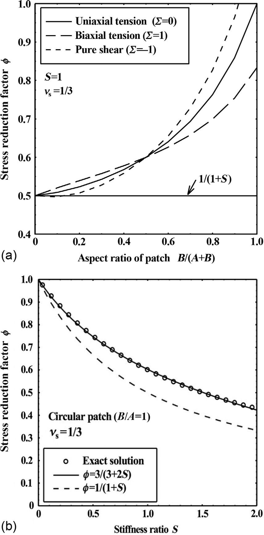
ToillustratetheimportantfeaturesofEquation (1.1),thevariationofthestressreductionfactor ϕ withthepatchaspectratioisshownin Figure1.9a forthreeloadingconfigurations:(i)uniaxialtension(Σ ¼ 0),(ii)equalbiaxialtension(Σ ¼ 1),and (iii)pureshear(Σ ¼ 1),setting S ¼ 1and νs ¼ 1/3forallcases.Itcanbeseenthat
FIGURE1.9
Variationofstress-reductionfactorwith(a)aspectratioforanellipticalpatchofsemiaxes A and B underuniaxialtension,biaxialtension,andpureshear.(b)Stiffnessratio S for acircularpatch(DuongandWang,2007).
thereislittlevariationforaspectratiosrangingfrom B/A ¼ 0(horizontalstrip)to B/A ¼ 1(circularpatch),sothatforpreliminarydesigncalculations,onecanconvenientlyassumethepatchtobecircular,toreducethenumberofindependentparameters.ItisalsonotedfromEquation (1.1) thatfor νs ¼ 1/3andacircularpatch (A/B ¼ 1),thestress-reductionfactor ϕ becomesindependentofthebiaxialityratio Σ .Asillustratedin Figure1.9a,thecurvesfor Σ ¼ 0and Σ ¼ 1crossoverfor B/A ¼ 1,indicatingthat,foracircularpatch,thetransversestress σ 1x ¼ Σσ 1 does notcontributetotheprospectivestress,sothatthisparametercanalsobeignored inpreliminarydesignestimates.Inthisparticularcase,thestress-reductionfactor ϕ dependsonthestiffnessratio S only,asdepictedin Figure1.9b.Forarectangular patchspanningacrossawidthoftheskin, ϕ canbeobtainedfromaone-dimensional analysisas ϕ ¼ σ 1/(1+ S).Thisone-dimensionalresultisalsoplottedin Figure1.9a and b forreference.Theone-dimensionalsolutionignorestheloadattractioneffect ofapatchandoverestimatesthereductioninskinstress.ForthespecialcaseofcircularpatchandPoisson’sratiobeingequalto1/3,solution (1.1) canbesimplifiedto become,
Ontheotherhand,thepeaktressintheskinoutsidethepatchatlocation B canbe expressedintermsoftheappliedstress σ 1 as:
Hence,thestiffnessincreasebythedoublerelevatestheskinstressat B,yieldinga localstressconcentrationfactorequalto
However,thepresenceofadoublerreducestheskinstressatlocation A tobelowthe appliedstress.Theratiobetweentheskinstressandtheappliedstressat A is
1.6 EFFECTOFTAPERANDSCARFRATIOSONJOINTDESIGN
Thedesignofabondedrepairtypicallyinvolvesanalyzingastructuraljointthatrepresentsthemosthighlyloadedsectionsofarepair(WangandGunnion,2008a,b).To minimizethepeakadhesivestressinastructurejoint,thepatchedgeisnormally taperedasinadoublerrepairorscarfedasinaninternalrepairintoasmoothsurface orintomultiplediscretesteps.Taperandscarfratiosarefoundtosignificantlyaffect thepeakadhesivestresses,andthus,theperformanceofstructuraljoints.Theeffect
oftaperandscarfratiosonthejointdesignisthereforeconsideredinthissection. However,againforanintroductorypurpose,thiseffectwillbedemonstratedonly forinternalrepairs(i.e.,scarfandsteppedrepairs).
Twodifferentapproachesaretypicallyemployedtodeterminethegeometryof steppedandscarfrepairs,mainlythetaperanglethatmayvarywiththelaminate orientationrelativetotheloadingdirections,tomeetstrengthrequirements.The mostwidelyusedapproachconsidersthatthebondedrepairsdonotcontainany preexistingflawsorin-servicedamage,similartothesafe-lifemethodologyfor designingmetallicaircraftcomponents.Thesecondapproachconsidersthepresenceofpreexistingflawsandservice-induceddamageindeterminingthetaper angleofscarf,similartothedamagetolerancemethodologyfordesignofmetallic aircraftstructures.Abriefreviewofthesetwoapproachesispresentedbelow.
1.6.1 SAFE-LIFEAPPROACH
Dependingonthebehavioroftheadhesiveandtheoperatingtemperature,thecohesivefailureofabondedjointingeneralcanbecharacterizedasanadhesiveplastic collapse,abrittlecohesivefailure,oraductilecohesivefailure.Foreachcase,the adhesivestressesofascarfjointwithoutanyflawandthemaximumallowable taperangletoavoidajointfailurewillbedeterminedbyadifferentmethodusing differentapproximations.Forajointfailurebyaplasticcollapselimit,thetaper angleofthescarfcanbeexpressedintermsoftheadhesiveshearstrengthand therequireddesignultimateload(Baker,1996;Oplinger,1998;Wangand Gunnion,2008a,b),
wherethesubscript p denotesthetaperanglecorrespondingtotheplasticcollapse limit.Inderivingtheabovesolutionforthescarftaperangle,thebondlineshear stressisassumedtobeconstant.Thisapproachhasevolvedhistoricallyfromwood joiningprocesses.Forfiber-reinforcedcompositesconsistingofplieswithdifferent orientations,thebondlinestresshasbeenfoundtovarywidelyalongthescarf(Wang andGunnion,2008a,b).Duetothehighstiffnessofpliesalongthemainloading direction,stressconcentrationsoccurattheterminationoftheseplies.Conversely, pliesorientedatlargeanglesfromthemainloadingdirectioncarrymuchlowerload, leadingtolowstressregionsalongthescarf.Underveryhighoperatingtemperatures whentheadhesivecanundergosignificantlevelofplasticdeformationpriortofailure,Equation (1.8) isapplicabletocompositejoints.Inthiscasetheadhesiveshear stressreachesanearuniformdistribution,withthejointfailureasaresultofshear plasticcollapseoftheadhesivelayer.
Incontrast,whenthejointfailureisdominatedbybrittlefailureoftheadhesives, whichmayarisefromtheuseofverybrittleadhesivesorductileadhesivesoperating atverylowtemperatures,itisimportanttoaccountforthehighstressconcentrations inadhesiveshearstressinscarfjointsbetweencompositeadherends.Adoptingthe
maximumshearstresscriterion,themaximumscarfangleis,withthesubscriptb denotingbrittlefailuremodeofadhesiveundersheardeformation,
where Kt denotesthestressconcentrationfactorofadhesiveshearstressinscarfjoint (WangandGunnion,2008a,b).Anapproximatesolutionofthestressconcentration factorisgivenbythefollowingexpression:
where n and E denote,respectively,thenumberofpliesofagivenorientationwith respecttothemainloadingdirection,andthepertinentelasticmodulus.Thesubscripts0, 45,and90denotetheorientationangleofplies,with ntotal ¼
0 + n 45 + n90.DetailedfiniteelementanalyzeshaveshownthatEquation (1.8) providesanupperbound,henceaconservativedesignsolutionofthe maximumstressconcentrationfactor(WangandGunnion,2008a,b).Becausethe shear-lageffectfromtheadhesivelayerisignored,theactualstressconcentration factorforjointswithhighlyflexiblebond,suchasthickbondlinesorlow-stiffness adhesives,maybelessthanthatgivenbyEquation (1.8)
Moststructuraladhesivesundergoacertainlevelofplasticdeformationpriorto failure,especiallyatelevatedtemperatureclosetotheirglasstransitiontemperatures. Inthiscase,theirfailureisbestcharacterizedbyacohesiveductilefailure.Aductile failurerequiresafirst-orderestimateofthetotaladhesiveshearstrain,accountingfor plasticdeformationoftheadhesive,whichcanbeobtainedbytheNeuber’srule.The Neuber’srulehasbeenextensivelyusedtoanalyzeplasticdeformationatnotchroot (Wangetal.,1999;Knopetal.,2000).ExpressingtheNeuber’sruleintermsofthe shearstressandshearstrainintheadhesivebondgives
wheretheaverageshearstress
σ 1 isthefarfieldappliedstress, α isthetaperangle,and τ f isagaintheadhesiveshear strength.Hence,themaximumshearstrainis
Ifthebondstrengthistakentobewhenthemaximumshearstrainreachesacritical value(WangandGunnion,2008a,b)atthedesignultimateloadof σ DUL,i.e., γ max ¼ γ f,where γ f denotesthefailurestrainoftheadhesive,themaximumscarf angletoavoidductilecohesivefailureis
Insummary,thesolutionsgivenbyEquations (1.8),(1.9),and (1.14) furnishacompletesetofrapiddesigntoolsfordeterminingtheappropriatescarfangleforadhesivesundergoingfull-plastic,brittle,andductilefailures,respectively.
1.6.2 DAMAGETOLERANCEAPPROACH
Forprimaryorsafety-criticalstructures,airworthinessregulations(FAA,2005, 2010)prescribethatthe(a)scarfedstructures,withoutrepair,mustmeetthedesign limitload;and(b)repairedstructurescansustainthedesignultimateloadinthe presenceofdamagelargerthanthedetectionlimit(Wangetal.,2011a).Inother words,bondedscarfrepairsofsafety-criticalstructuresmustbedemonstrated,by experimentsandanalysis,toexceedthedesignultimateloadinthepresenceofdisbonds.Recentinvestigationshaverevealedthatimpactdamage(HarmanandWang, 2007;Kimetal.,2012)andpreexistingflaws(Wangetal.,2011b;Gohetal.,2013) haveasignificanteffectonascarfjoint’sload-carryingcapacityandfatigueendurance(Cheuketal.,2002).
Consideringascarfjointcontainingadisbondoflength a,asillustratedin Figure1.6b,theultimatetensilestrengthofthisjointdependsonthelengthofthe initialflawanditspositionalongthejoint.Usingthefracturemechanicsapproach, thecriticalconditionforthedisbondgrowthcanbeexpressedas:
Theparameters YI and YII arethecrackgeometryfactorthatvarywithcracksizeand scarfangle,foragivenlaminate.Definitionsofparameters η, β ,and Eeff,together withthevaluesofthegeometryfactors YI and YII foraquasi-isotropiclaminate arepresentedin Gohetal.(2013).Thenecessaryscarfanglerequiredtosustain thedesignultimateloadcanbedeterminedbysolvingEquation (1.15) usinganiterativetechnique,asdiscussedin Gohetal.(2013).
1.6.3 STEPPEDREPAIRS
Forasteppedrepair,asillustratedin Figure1.5b,bondlinestressesmayexhibita higherlevelofstressconcentrationduetothesharpcorners.Additionalconsiderationisthereforepresentedinthissubsection.Theadhesiveshearandpeelstresses
canbedeterminedusingthemultistepjointanalysismethod(ESDU,1998).Similar toscarfrepairs,ultimatestrengthofsteppedrepairsdependontheductilityofthe adhesive.Inthecaseofplasticcollapse,thetotallengthofthestepsneededtosustain thedesignultimateloadofasteppedjointwithatotalthickness t is
whichgivesanequivalenttaperanglesimilartothatdescribedbyEquation (1.8) when τ f ismuchlessthan σ DUL.
1.7 SUMMARY
Arapidriseintheuseofadvancedfiber-reinforcedpolymercompositesonaerospace,automotive,andcivilstructuresdemandsnewdevelopmentsindesignand analysismethodologies,applicationprocesses,andnondestructiveinspectiontechniquesforbondedjointsandbondedrepairs.However,themainfocusofthisbook isdevotedtodoublerandscarfrepairsofcompositeairframestructuresalongwith theirrepresentativejoints.First,theairworthinessrequirementsfortheserepairsand thecriticalityofairframestructureanddamagearebrieflysummarized.Itisfollowed byabriefoverviewoftherepairanalysisprocess.Rapiddesigntoolsfordetermining repairedpatchparameterssuchasshapeaspectratio,stiffnessratio,andtaperangle arefinallyintroduced.Furtherdevelopmentsalongandbeyondthesetopicswillbe describedindetailintheremainingchaptersofthebook.
REFERENCES
Adams,R.,2011.Nondestructivetesting.In:daSilva,L.M., Ochsner,A.,Adams,R.(Eds.), HandbookofAdhesionTechnology.Springer,Berlin,Heidelberg,pp.1049–1069. Baker,A.A.,1996.Joiningandrepairofaircraftcompositestructures.Mech.Eng.Trans. ME21(No.1&2),1–59.
Baker,A.A.,Rose,L.R.F.,Jones,R.,2002.AdvancesintheBondedCompositeRepairof MetallicAircraftStructure.Elsevier,Amsterdam.
Cheuk,P.T.,Tong,L.,Wang,C.H.,Baker,A.,Chalkley,P.,2002.Fatiguecrackgrowthin adhesivelybondedcomposite-metaldouble-lapjoints.Compos.Struct.57(1-4),109–115. Duong,C.N.,Wang,C.H.,2007.CompositeRepair:TheoryandDesign.Elsevier,Oxford. ESDU,1998.Inelasticshearstressesandstrainsintheadhesivesbondinglapjointsloadedin tensionorshear.IHSESDU,London.
FAA,2005.FAAFederalAviationRegulations(FAR)Part23,Section573-DamageToleranceandFatigueEvaluationofStructure.
FAA,2010.CompositeAircraftStructure:AdvisoryCircular(AC)20-107B,Change1,FAA. Goh,J.Y.,Georgiadis,S.,Orifici,A.C.,Wang,C.H.,2013.Effectsofbondlineflawsonthe damagetoleranceofcompositescarfjoints.Compos.PartAAppl.Sci.Manuf. 55,110–119.
Harman,A.B.,Wang,C.H.,2007.Damagetoleranceandimpactresistanceofcompositescarf joints.In:ICCM-16,Kyoto,Japan.
Kim,M.K.,Elder,D.J.,Wang,C.H.,Feih,S.,2012.Interactionoflaminatedamageand adhesivedisbondingincompositescarfjointssubjectedtocombinedin-planeloading andimpact.Compos.Struct.94,945–953.
Knop,M.,Jones,R.,Molent,L.,Wang,C.,2000.OntheGlinkaandNeubermethodsfor calculatingnotchtipstrainsundercyclicloadspectra.Int.J.Fatigue22(9),743–755.
Oplinger,D.W.,1998.Mechanicalfasteningandadhesivebonding.In:Peters,S.T.(Ed.), HandbookofComposites.Chapman&Hall,London,pp.610–666.
Ridha,M.,Wang,C.H.,Chen,B.Y.,Tay,T.E.,2014.Modellingcomplexprogressivefailure innotchedcompositelaminateswithvaryingsizesandstackingsequences.Compos.Part AAppl.Sci.Manuf.58,16–23.
Wang,C.H.,Gunnion,A.J.,2008a.Onthedesignmethodologyofscarfrepairstocomposite laminates.Compos.Sci.Technol.68(1),35–46.
Wang,C.H.,Gunnion,A.J.,2008b.Optimumshapesforminimisingbondstressinscarf repairs.Aust.J.Mech.Eng.6(2),153–158.
Wang,C.H.,Gunnion,A.J.,2009.Optimumshapesofscarfrepairs.Compos.A:Appl.Sci. Manuf.40(9),1407–1418.
Wang,C.H.,Guo,W.,Rose,L.R.F.,1999.Amethodfordeterminingtheelastic-plastic responseaheadofanotchtip.J.Eng.Mater.Technol.Trans.ASME121(3),313–320.
Wang,C.H.,Goh,J.Y.,Ahamed,J.,Glynn,A.,Georgiadis,S.,2011a.Damagetoleranceanalysisofadhesivelybondedrepairstocompositestructures.In:18thInternationalConferenceonCompositeMaterials.Jeju,SouthKorea.
Wang,C.H.,Gunnion,A.J.,Orifici,A.C.,Rider,A.,2011b.Residualstrengthofcomposite laminatescontainingscarfedandstraight-sidedholes.Compos.A:Appl.Sci.Manuf. 42(12),1951–1961.
Wang,C.H.,Venugopal,V.,Peng,L.,2015.Steppedflushrepairsforprimarycompositestructures.J.Adhes.91(1-2),95–112.