https://ebookmass.com/product/analysis-and-design-of-
Instant digital products (PDF, ePub, MOBI) ready for you
Download now and discover formats that fit your needs...
Prestressed Concrete 5th Edition Warner Foster
https://ebookmass.com/product/prestressed-concrete-5th-edition-warnerfoster/
ebookmass.com
Prestressed Concrete: A Fundamental Approach 5th Edition Edward Nawy
https://ebookmass.com/product/prestressed-concrete-a-fundamentalapproach-5th-edition-edward-nawy/
ebookmass.com
Reinforced Concrete Structures Analysis and Design (2nd Edition) David A Fanella
https://ebookmass.com/product/reinforced-concrete-structures-analysisand-design-2nd-edition-david-a-fanella/
ebookmass.com
Administracio■n de compras y abastecimientos P. Fraser Johnson
https://ebookmass.com/product/administracion-de-compras-yabastecimientos-p-fraser-johnson/
ebookmass.com
Principles and Practice of Radiation Therapy E Book 4th Edition, (Ebook PDF)
https://ebookmass.com/product/principles-and-practice-of-radiationtherapy-e-book-4th-edition-ebook-pdf/
ebookmass.com
Microsoft Outlook 365 Complete: In Practice, 2021 Edition Randy Nordell
https://ebookmass.com/product/microsoft-outlook-365-complete-inpractice-2021-edition-randy-nordell/
ebookmass.com
The Business Student's Guide to Sustainable Management -Principles and Practice 2nd Edition Molthan-Hill
https://ebookmass.com/product/the-business-students-guide-tosustainable-management-principles-and-practice-2nd-edition-molthanhill/
ebookmass.com
The Thirteenth-Century Animal Turn: Medieval and TwentyFirst-Century Perspectives 1st ed. Edition Nigel Harris
https://ebookmass.com/product/the-thirteenth-century-animal-turnmedieval-and-twenty-first-century-perspectives-1st-ed-edition-nigelharris/
ebookmass.com
Advances in the Practice of Public Investment Management 1st ed. Edition Narayan Bulusu
https://ebookmass.com/product/advances-in-the-practice-of-publicinvestment-management-1st-ed-edition-narayan-bulusu/
ebookmass.com
Loving the Wolf: A Fated Mates Romance Paige Tyler https://ebookmass.com/product/loving-the-wolf-a-fated-mates-romancepaige-tyler/
ebookmass.com
ANALYSISAND DESIGNOF PRESTRESSED CONCRETE DIHU
AssociateProfessor,SchoolofCivilEngineering, CentralSouthUniversity,China
Elsevier
Radarweg29,POBox211,1000AEAmsterdam,Netherlands
TheBoulevard,LangfordLane,Kidlington,OxfordOX51GB,UnitedKingdom 50HampshireStreet,5thFloor,Cambridge,MA02139,UnitedStates
© 2022CentralSouthUniversityPress.PublishedbyElsevierInc.AllRightsReserved.
Nopartofthispublicationmaybereproducedortransmittedinanyformorbyanymeans,electronic ormechanical,includingphotocopying,recording,oranyinformationstorageandretrievalsystem, withoutpermissioninwritingfromthepublisher.Detailsonhowtoseekpermission,furtherinformationaboutthePublisher’spermissionspoliciesandourarrangementswithorganizationssuchas theCopyrightClearanceCenterandtheCopyrightLicensingAgency,canbefoundatourwebsite: www.elsevier.com/permissions .
Thisbookandtheindividualcontributionscontainedinitareprotectedundercopyrightbythe Publisher(otherthanasmaybenotedherein).
Notices
Knowledgeandbestpracticeinthis fieldareconstantlychanging.Asnewresearchandexperience broadenourunderstanding,changesinresearchmethods,professionalpractices,ormedicaltreatmentmaybecomenecessary.
Practitionersandresearchersmustalwaysrelyontheirownexperienceandknowledgeinevaluating andusinganyinformation,methods,compounds,orexperimentsdescribedherein.Inusingsuch informationormethodstheyshouldbemindfuloftheirownsafetyandthesafetyofothers,including partiesforwhomtheyhaveaprofessionalresponsibility.
Tothefullestextentofthelaw,neitherthePublishernortheauthors,contributors,oreditors,assume anyliabilityforanyinjuryand/ordamagetopersonsorpropertyasamatterofproductsliability, negligenceorotherwise,orfromanyuseoroperationofanymethods,products,instructions,orideas containedinthematerialherein.
ISBN:978-0-12-824425-8
ForinformationonallElsevierpublicationsvisitourwebsiteat https://www.elsevier.com/books-and-journals
Publisher: MatthewDeans
AcquisitionsEditor: GlynJones
EditorialProjectManager: NaomiRobertson
ProductionProjectManager: SuryaNarayananJayachandran
CoverDesigner: GregHarris
TypesetbyTNQTechnologies
Listoffigures Figure1.1 Schematicdiagramofthestressdistributionofanaxialtensile member.2
Figure1.2 Stressdistributionatthemidspansectionofasimplysupported beam.3
Figure1.3 Schematicdiagramofasimplysupportedbeam.4
Figure1.4 Aprestressedconcretebeamarrangedwithparabolictendons.6
Figure1.5 PictureoftheBeipanjiangsuperbridgefromJipingGuo.11
Figure2.1 Schematicdiagramofthetime-dependentstrainversusstress ofconcrete.24
Figure2.2 Developmentofdelayedelasticstrainwithtime.27
Figure2.3 Developmentofdelayedplasticstrainwithtime.28
Figure2.4 Influenceofnotionalsizeoncreep.28
Figure2.5 Developmentofstrengthwithtime.29
Figure2.6 Helicalribwireandindentedwire.33
Figure2.7 Cross-sectionsofprestressingsteelstrands.35
Figure2.8 Shapeofaprestressedscrew-threadsteelbar.36
Figure2.9 Cross-sectionofunbondedprestressedstrands:(1)strands;(2) sheathings;(3)coating.37
Figure2.10 Structuraldiagramoftypicalexternalcables:(1)unbonded strand;(2)HDPEsheath;(3) fillingmaterial;(4)outersheath; (5)bondedstrand.38
Figure2.11 Stress straincurveofprestressingthreadedbars.38
Figure2.12 Schematicdiagramofcold-drawnaging.39
Figure2.13 Stress straincurveofprestressingsteelwires.40
Figure2.14 Stressrelaxationversusloadingduration.49
Figure2.15 Temperatureeffectonthe finalvalueoftherelaxation.49
Figure3.1 Schematicdiagramofthepretensioningmethod.57
Figure3.2 Schematicdiagramofpost-tensioningmethod.58
Figure3.3 Workersarrangingtheductsfortendonsinaboxgirderin aprefabricationplant.60
Figure3.4 Workersarrangingtheductsfortendonsinthewebofa continuousboxgirder.60
Figure3.5 Diagramofclip-typeanchoragesystemforstrands: (1)anchorbackingplate;(2)clip;(3)anchorageplate; (4)spiralreinforcement;(5)strands;(6)corrugatedduct.63
Figure3.6 Structureofaclip.64
Figure3.7 Clip-typeanchoragesystem.64
Figure3.8 Diagramoftheconicalanchorstructure.65
Figure3.9 Conicalanchor.65
Figure3.10 Diagramofthescrewendrodanchor:(1)reservedhole; (2)washer;(3)rowgroove;(4)threadedsteelbar; (5)anchornut;(6)bearingplate;(7)spiralreinforcement.66
Figure3.11 DiagramofBBRVanchorage.66
Figure3.12 Diagramoftherivet-head-bearinganchoragesystem.67
Figure3.13 Nutanchorage.67
Figure3.14 End-rivetanchoragesystem.68
Figure3.15 Extrudinganchoragesystem.68
Figure3.16 Diagramof floweranchorage:(1)duct;(2)restrainring; (3)spiralreinforcement;(4)strands;(5)bracing;(6)bulbor flowerportion.69
Figure3.17 Floweranchoragesystem.69
Figure3.18 Couplerforprestressingstrands.70
Figure3.19 MechanicalclampinganchorageforasingleFRProdorwire.70
Figure3.20 MechanicalclampinganchorageforasingleFRPplate.71
Figure3.21 Adhesiveanchoragesystem.71
Figure3.22 AnchoragesystemforanFRPplate.72
Figure3.23 Double-actingjackwiththroughcore.72
Figure3.24 Temporaryanchorplatemoveswithram.73
Figure3.25 Workersoperatingtheintelligenttensioningsystemtostretch thetendons.73
Figure3.26 Head-anchorjack.74
Figure3.27 Pullrodjack.74
Figure3.28 Mouthforgrouting.75
Figure3.29 Cementmortargroutingusinganintelligentgroutingsystem.75
Figure3.30 Beforeandaftersealingforanchorages.77
Figure4.1 Knowledgesystemofprestressedconcrete.80
Figure4.2 Majordesignsteps.A1 Expressionsofdesignparameterby rewritingtheformulasobtainedintheanalysis;A2 Formulas intheanalysis.90
Figure5.1 Prestresslossesinprestressedconcretemembers.(A)Prestress lossesinaposttensionedmember.(B)Prestresslossesina pretensionedmember.97
Figure5.2 Twoturnsoftendonswithintheanchoragedevice.98
Figure5.3 Diagramoffrictionallosscalculation.(A)Curvedprestressing tendon.(B)Forceofmicroprestressingtendon.98
Figure5.4 Schematicdiagramofthebalancedcantilevermethod.102
Figure5.5 sl 2 ðxÞ occursinalengthof lf .103
Figure5.6 Typicalprofileoftheprestressingtendon.106
Figure5.7 Distributionoftendonstressattheanchorageset.107
Figure5.8 Profilesoftheprestressingtendons.123
Figure5.9 Cross-sectionatmidspan.126
Figure5.10 Arrangementoftendons.126
Figure5.11 GeometricrelationinthecurvedsegmentBC.128
Figure5.12 Sectiondimension.135
Figure5.13 Convertedsection.136
Figure6.1
Equivalentloadsofthelinearprestressingtendon.(A)Asimply supportedbeamwithastraighttendon.(B)Tensionintendon. (C)Equivalentloadsonconcretestructure.142
Figure6.2 Equivalentloadsbyabroken-linetendon.(A)Asimply supportedbeamwithbroken-linetendon.(B)Forceson tendon.(C)Equivalentloadsonconcretestructure.143
Figure6.3 Equivalentloadsbyaparabolictendon.(A)Asimply supportedbeamwithaparabolictendon.(B)Forceson tendon.(C)Equivalentloadsonconcretestructure.145
Figure6.4 Diagramoftheprimaryinternalforces.(A)Asimplysupported beamwithaparabolictendon.(B)Internalforcesonconcrete section.146
Figure6.5 Diagramforthesolutionofsecondaryinternalforceand totalinternalforce.(A)Two-spanbeamarrangedwith eccentricstraighttendons.(B)Camberduetoprestressingforce whensupportBisremoved.(C)Camberincontinuousbeam duetoprestresingforce.(D)ReactiononsupportB.
(E)Momentcausedby Rb.(F)Momentcausedby Np. (G)FinalMoment.148
Figure6.6 Diagramofthelineartransformationandshearforce.
(A)Acontinuousbeamarrangedwithconstanteccentric tendons.(B)ThetendonsarearrangedalongtheC-line. (C)Shearforceinbeam(A)duetotheprestressingforce. (D)Shearforceinbeam(B)duetotheprestressingforce.151
Figure6.7 Connectseveralsimplysupportedbeamstoacontinuousbeam. (A)Threesimplysupportedbeamsbeforeconnecting. (B)Acompletedprestressedconcretecontinuousbeam.152
Figure6.8 ConnectseveralT-structurestoacontinuousbeam.
(A)TwoT-structuresalongwithtwoendpartsbefore connecting.(B)Acompletedprestressedconcretecontinuous beam.153
Figure6.9 Connecttwosimplysupportedbeamstoacontinuousbeam. (A)Structuresin firststage.(B)Momentin firststagestructure causedby Np.(C)Continuousbeam(structurein finalstage). (D)Changeofmomentduetocreep.154
Figure7.1 Sectionstressesatvariousstages.159
Figure7.2 Bendingmomentversusverticaldeformationofa flexural member.160
Figure7.3 Temporarysupportsduringtransportation.166
Figure7.4 Relationsofstrainchangeintendonsandreinforcingsteels.169
Figure7.5 Diagramforcalculatingthegeneralizedprestressingforce anditseccentricity.170
Figure7.6 Analysisofshearstressandprincipalstresses.177
Figure7.7 Diagramofthecrackingmomentcalculation.181
Figure7.8 Diagramofthecorrectioncoefficientcalculation.182
Figure7.9 Decomposedstatesofstressinacrackedsection.185
Figure7.10 SchematicdiagramofstresscalculationinthecrackedT-section.189
Figure7.11 Schematicdiagramofcross-section.196
Figure7.12 Schematicdiagramofforcetransmissioninapretensioned member.205
Figure7.13 Anchoragezonetypes.208
Figure7.14 Stressdistributioninanchoragezone.208
Figure7.15 Distributionoftransversestressunderlocalcompression.209
Figure7.16 Tensionregionsinthetriangulartoothblockanchoragezone.210
Figure8.1 Schematicdiagramofrotationofthebeamend.213
Figure8.2 Deflectionvarieswiththemoment.214
Figure8.3 Diagramofcalculatingdeflection.215
Figure8.4 Relationbetween Kcr anddeflection.219
Figure8.5 Variationofthesectionalcurvature.221
Figure8.6 Bendingofasimplysupportedbeamsubjectedtoauniformly distributedload.228
Figure8.7 Simplysupportedbeamsubjectedtoaconcentratedload.229
Figure8.8 Schematicdiagramofrotationatthebeamend.231
Figure8.9 Schematicdiagramofreinforcementatthemidspansection.233
Figure8.10 Dimensionofthemidspansectionoftheboxgirder.235
Figure8.11 ZKliveloadmodel.236
Figure8.12 EquivalentloadsofZKonthegirder.238
Figure8.13 Schematicdiagramofcrackingina flexuralmember.244
Figure8.14 Calculationoftheeffectiveareaofconcreteintension.248
Figure8.15 Dimensionandreinforcementarrangementatthe midspansection.253
Figure8.16 Dimensionandreinforcementarrangementatthemidspan section.255
Figure8.17 Dimensionandreinforcementarrangementatthemidspan section.257
Figure9.1 Equivalentstressblock.263
Figure9.2 Stressandstraininaprestressedconcrete flexuralsection: ①,failureoftheover-reinforcedsection; ②,failureofthe balancedsection; ③,failureoftheunder-reinforcedsection.265
Figure9.3 Stressversusstraininsteelwiresandstrands.267
Figure9.4 Typicalprestressedconcreterectangularsectionsubjected tobendingmoment.269
Figure9.5 Strainrelationinthecompressionzone.271
Figure9.6 TypicalprestressedconcreteT-section.272
Figure9.7 Strainsofprestressingtendonsinthecompressionzone:
Figure9.8 Dimensionandreinforcementsatthemidspansection.275
Figure9.9 Dimensionandreinforcementatthemidspansection.277
Figure9.10 Dimensionandreinforcementatthemidspansection.279
Figure9.11 Crackingpatternsinasimplysupportedconcretebeam: ①, flexuralregion; ②, flexure-shearregion; ③,webshearregion.281
Figure9.12 Crackingperpendiculartothetensileprincipalstress.281
Figure9.13 Crackingbetweentheconcentratedloadandthesupport.282
Figure9.14 Failurepatternsduetoshearforce.282
Figure9.15 Shearbearingcapacitycalculationdiagram.286
Figure9.16 Relationshipbetweentheshearspanratioandtheshear bearingcapacity.290
Figure9.17 Calculationdiagramofshearbearingcapacitywithan inclinededgeinthetensionzone.292
Figure9.18 Calculationdiagramof flexuralbearingcapacityofthe obliquesection.294
Figure9.19 Arrangementoflongitudinalprestressingtendons.296
Figure9.20 Arrangementoflongitudinalprestressingtendons.298
Figure9.21 Arrangementoflongitudinalprestressingtendons.300
Figure9.22 Torsionalsections(h > b).304
Figure9.23 Correlationbetweenshearandtorsionbearingcapacity.306
Figure9.24 Dimensionandreinforcementofrectangularsection.310
Figure9.25 Shearmodelforthefailuremechanismofconcrete underlocalcompression.313
Figure9.26 Calculationdiagramfor Ab inQ/CR9300-2018.315
Figure9.27 Calculationdiagramfor Ab inJTG3362-2018and GB50010-2010.316
Figure9.28 Calculationdiagramfor Fl ;s bythehoopingstrengthening theory.317
Figure9.29 Arrangementofindirectreinforcement.319
Figure9.30 Burstingforceattheendanchors.323
Figure9.31 Spallingforceattheendanchors.324
Figure9.32 Tensionsattheedgeregionclosetotheendsectionwithan anchorage.325
Figure9.33 Tensionregionsintheanchoragezone.325
Figure10.1 Typicalcross-sectionsofprestressedconcretebeams.331
Figure10.2 Diagramforestimatingtheareaofprestressingtendons.336
Figure10.3 Thethreadedsteelbarsinthepretensionedsleepersfora ballastlesstracksysteminahigh-speedrailway.339
Figure10.4 Schematicdiagramoftheverticaltendonsinaboxsection.340
Figure10.5 SchematicdiagramofthetendonboundaryinaT-beam.341
Figure10.6 Schematicdiagramofreinforcingsteelsintheanchoragezone.348
Figure11.1 Typicalprestressedconcreterectangularsectionsubjectedto eccentrictensionforce.356
Figure11.2 Stressdistributionacrossconcretesectiondepth.359
Figure11.3 Calculationdiagramofbearingcapacityofarectangular sectionundereccentriccompression.364
Figure11.4 CalculationdiagramofbearingcapacityofaT-sectionunder eccentriccompression.366
Figure11.5 Arrangementofprestressingtendonsandreinforcingsteels.368
Figure11.6 Calculationdiagramofthebearingcapacityoftheannular sectionundereccentriccompression.375
Figure12.1 Crackingofanunbondedprestressedconcretebeamwithout reinforcingsteels.380
Figure12.2 Structuraldiagramoftypicalcircularsleeveanchorage: (1)clip;(2)anchorring;(3)bearingplate;(4)spiralreinforcing steelbar;(5)unbondedstrands;(6)cavemold;(7)plasticcap; (8)microexpansive fineaggregateconcreteornonshrinkage cementmortar.382
Figure12.3 Structuraldiagramoftypicalintegrated-bearing-plate anchorage:(1)clip;(2)integrated-bearing-plate;(3)unbonded strands;(4)spiralreinforcingsteelbar;(5)plasticsealingsleeve; (6)cavemold;(7)sealingconnectorandnut;(8)sealingcover; (9)microexpansive fineaggregateconcreteornonshrinkage cementmortar.382
Figure12.4 Structuraldiagramoftypical fixing-endanchorage (1)extrusionanchorage;(2)specialanticorrosivegrease; (3)sealingcover;(4)plasticsealingsleeve;(5)pressuresealing cover;(6)sealingring;(7)thermoplasticpressuresealingsleeve.382
Figure12.5 Bendingmomentversusdeflectionofanunbonded prestressedconcrete flexuralmember.384
Figure12.6 Stressoftheunbondedandbondedtendonsversusthe bendingmoment.384
Figure13.1 Typicallayoutsofexternalcableinasimplysupportedbeam.398
Figure13.2 Deformationrelationbetweentheexternalcableandbeam.398
Figure13.3 Componentsofanexternalcableassembly:(1)anchorage; (2)conduit;(3)sealingdevicesandjoint;(4)externalcable; (5)dampingdevice;(6)steeringdevice;(7)spiralreinforcing steelbar.400
Figure13.4 Structuraldiagramoftypicalanchoragesforexternalcables: (1)protectivecover;(2)anchorplate;(3)baseplate;(4)spiral reinforcingsteelbar;(5)connectingpipe;(6)isolationbushing; (7)reservedsectionforstretching;(8)nut;(9)outersheath; (10)conduit.401
Figure13.5 Structuraldiagramoftypicalsteeringdevices:(1)blocktype; (2)transverseribtype;(3)verticalribtype;(4)beamtype.402
Figure13.6 Layoutdiagramoftheprestressingstrandsinthesteeringgear: (1)steelpipe;(2)unbondedstrand;(3)HDPEsheath; (4)bondedstrand;(5)cementmortar;(6)guidepipe; (7)accessorystructure.402
Figure13.7 Atypicaldampingdevice:(1)adjustablepullrod; (2)rubbercushion;(3)haverbuckle;(4)externalcable.403
Figure13.8 Calculationdiagramofstresschangeinexternaltendon.406
Figure13.9 TypicalexternallyprestressedconcreteT-section.408
Figure13.10 TypicalexternallyprestressedconcreteT-section.411
Figure13.11 Calculationdiagramofshearbearingcapacity.412
Figure13.12 Diagramforcalculationofthegeneralizedprestressingforce anditseccentricity.414
Listoftables Table2.1 Characteristicstrengthsofconcrete(MPa).18
Table2.2 Designvaluesofconcretestrength(MPa).19
Table2.3 Modulusofelasticityofconcrete(104 MPa).20
Table2.4 Correctioncoefficient gr forfatiguecompressivestrength.21
Table2.5 Correctioncoefficient gr forfatiguetensilestrength.21
Table2.6 Fatiguemodulusofconcrete(104MPa).22
Table2.7 Designvaluesoffatiguecompressivestrengthofconcrete.22
Table2.8 Notionalcreepcoefficient.26
Table2.9 4f 1 and l.28
Table2.10 Notionalcreepcoefficientandshrinkagestrain.29
Table2.11 Notionalshrinkage εsho 10 6 .31
Table2.12 Notionalshrinkagestrain εu 10 4 .31
Table2.13 Categoryofprestressingsteelstrand.35
Table2.14 Mechanicalpropertiesofstress-relievedplainroundsteel wiresandribbedwires.41
Table2.15 Mechanicalpropertiesof1 7steelstrands.42
Table2.16 Mechanicalpropertiesof1 19steelstrands.43
Table2.17 Mechanicalpropertiesofprestressingthreadedsteelbars.44
Table2.18 Modulusofelasticityofsteels.45
Table2.19 Characteristictensilestrengthofprestressingsteels.45
Table2.20 Designtensileandcompressivestrengthsofprestressing steels(MPa).45
Table2.21 Characteristicstrengthofprestressingsteels.46
Table2.22 Designstrengthofprestressingsteels(MPa).46
Table2.23 Mechanicalpropertiesof fiberribs.47
Table2.24 AmbientimpactcoefficientonprestressingFRP.47
Table2.25 Ultimaterelaxationofsteelstrandsandwires(MPa).50
Table2.26 Ratioofintermediatevaluetoultimaterelaxation.51
Table2.27 RelaxationrateforprestressingFRP.51
Table2.28 Limitsofstressamplitudeoftheprestressingtendons(MPa).52
Table3.1 Requiredperformanceofcementmortar.76
Table4.1 Typesofactionforarailwaybridge.88
Table4.2 Partialfactorsoftheactionsforarailwaybridge.89
Table5.1 Coefficientofcontrolstressinprestressingtendonsat stretching.95
Table5.2a Thevaluesof m and k.100
Table5.2b Thevaluesof m and k.101
Table5.3 Valuesoftendonretractionduetoanchorageset(mm).102
Table5.4 Calculationofeffectivestressinprestressingtendonsinthecodes.121
Table5.5 Geometricparametersofthestrands.128
Table7.1 Valuesof a and b.165
Table7.2 Valuesofbasiccorrectioncoefficientconsideringtheinfluence ofplasticityofconcrete.184
Table7.3 Valuesof k1 and k2 .194
Table7.4 Valuesof g1 and g2 .195
Table7.5 Calculationofgeometricalproperties.198
Table7.6 Basicfatiguestrengthofreinforcingsteels(MPa).203
Table7.7 Influencecoefficientofstressratio g1 .203
Table7.8 Influencecoefficientofsteelbardiameter g2 .203
Table7.9 Influencingcoefficientofreinforcingsteelstrengthgrade g3 .204
Table7.10 Coefficientontheshapeofcommonlyusedprestressing tendons.206
Table7.11 Stress-transmissionlengthoftheprestressingtendon.206
Table7.12 Anchoragelengthoftheprestressingtendon (Q/CR9300-2018).207
Table7.13 Anchoragelengthoftheprestressingtendon(JTG3362-2018).207
Table8.1 Valuesofthestiffnessreductionfactor.217
Table8.2 Limitsforrailwaybeammaximumdeflection.230
Table8.3 Limitsforanintercityrailwaybeamend’smaximum rotationangle.231
Table8.4 Limitsforahigh-speedrailwaybeamend’smaximum rotationangle.232
Table8.5 Limitsforabuildingbeam’smaximumdeflection.232
Table8.6 Coefficientvaluesoftherelativebondpropertyof reinforcement.250
Table8.7 Allowablemaximumcrackwidth.252
Table8.8 Allowablemaximumcrackwidth.252
Table9.1 Valuesof b1 .264
Table9.2 Valuesofrelativeboundaryratioofthecompressionzone depth(xb )forrailwaybridges.268
Table9.3 Valuesofrelativeboundaryratioofthecompressionzone depth(xb )forhighwaybridges.268
Table10.1 Typicalratiosforprestressedconcretecontinuoushighway andrailwaybeams.333
Table10.2 Minimumconcretecoversforstraighttendonsfor highwaybridges(JTG3362-2018)(mm).342
Table10.3 Parametersforductsofprestressingtendons.343
Table11.1 Stabilitycoefficient.372
Table12.1 Thevaluesof m and k.385
Table12.2 ThecontrolstressintheunbondedprestressingFRP.385
Table13.1 Thevaluesof m and k.404
Table13.2 Thevaluesof k1 and k2 .419
Authorbiography Dr.DiHu iscurrentlyanassociateprofessorattheSchoolofCivilEngineering,Central SouthUniversity(CSU),Changsha,China.HereceivedaPh.D.degreeinCivil EngineeringfromCSUin2003,andfulfilledhispost-doctoralresearchontransportation engineeringinCSUduring2009 2010.HewasinvitedtostudyattheUniversityof BritishColumbia.Canadain2018.Dr.Hu’smainresearchincludesnonlinearanalysis ofbridgestructures,theoryofcreepeffectonconcretestructures,assessmentand strengtheningdesignofexistingbridges,andnoveljointsofconcrete-filledsteeltubular columnsinhigh-risebuildings.Inparticular,hehasproposedarefinedmethodfor calculatingthestresslossinprestressingsteelsduetoanchoragesetconsideringthe reverse-frictioneffect,arefinedmethod(automaticallystep-upmethod)andasimplified method(steelrestraintinfluencecoefficientmethod)foranalyzingthecreepeffecton prestressedconcretestructures.Dr.Huhaspublishedover40journalpapers,andtwo monographs TheoryofCreepEffectonConcreteStructures (2015)and DesignPrinciplesof PrestressedConcreteStructures (secondedition,2019).
Preface Prestressedconcretehasbeenoneofthemostwidelyusedstructuralmaterialsin railwaybridges,highwaybridges,andcivilandindustrialbuildingssinceits firsttrialapplicationover100yearsago.Aprimeexampleofitsapplicationisprestressedconcrete beams,whicharealmostthestrongestcompetitivesuperstructuresinbridgeswithspans from30to250m.Inviewoftheexcessivedeflectionandcrackingofsomebuiltlongspanbridgesthatarestillinserviceandthestrictrequirementsforhigh-speedrailway bridgesforlong-termcamberordeflection,combinedwiththedevelopmentofmaterial science,constructiontechnology,andstructuralanalysis,thefollowingtrendsare emerging:prestressingmaterialswithhigherstrengthandmechanicalpropertieswillbe developedandused,theconstructiontechnologieswillbemoreintelligentandstandardized,theperformance-baseddesignwilldrawincreasedattention,andmostoftheanalysis anddesignofprestressedconcretestructureswillbecompletedbycomputersthrough specificsoftwareratherthanbyhand.Accordingly,thetextbooksorreferencebooks fortheanalysisanddesignofprestressedconcretemustkeepupwithnewdevelopments.
Thisbooksystematicallyintroducesthebasicconceptsofprestressedconcreteand fundamentalprinciplesofanalysisanddesignforprestressedconcretestructuressubjected tobending,shear,tension,compression,andtorsionbasedontheultimatelimitstate method.
Themostdistinctfeatureofthisbookisthatthecalculationofprestresslossesina step-by-stepmannerfromtheconstructiontotheserviceperiodisexpoundedcomprehensively,andaneffective-stress-basedanalysissystemaswellasthecalculationformulas fordesignparametersattheserviceabilitylimitstateareconstructed.Theaccuratecalculationofeffectivestressinprestressingtendonsisthebasisofstressanalysis,crackcontrol, andlong-termdeflectionprediction.
Anotherdistinctfeatureofthisbookisthatitbuildsabridgebetweengeneralanalysis methodsandthesimplifiedapproachesprovidedintherelevantcodes.Forastrictly performance-baseddesignwiththepremiseofsufficientstrengthanddurability,when theprestresslossesduetofriction,creepandshrinkageofconcrete,andrelaxationof prestressingtendonsareconsideredcomprehensively,itisverycomplicatedandtedious tocarryoutstressanddeflectionanalysisofaprestressedconcretememberwithalarge numberofdifferentprestressingtendons.Forstaticallyindeterminateprestressedconcrete beamswithmultispans,itisalmostimpossibletocompletetheanalysisusingasimplified approach.Therefore,itisnecessarytoelaboratethepreciseanalysisapproaches. However,theassociatedcodesandtechnicalstandardsguidingthedesignoftenspecify thesimplifiedmethodsandapproximateformulasformanykeydesignparameters.
x Preface
Thisbook firstexpoundsthetrainofthoughtofgeneralanalysis,andthenintroduces simplifiedapproachestothecodes.Byreadingthisbook,readerswillbeabletoeasily masterthegeneralanalysisandsimplifiedcalculationstrategiesforpretensionedand post-tensionedconcretestructures,andcultivatetheirdesignability.
TheauthorsincerelythanksProf.TengWufromUniversityatBuffalo,Prof.Tony YangfromUniversityofBritishColumbia,Prof.WenyuJifromBeijingJiaotongUniversity,andProf.XiaojunWeiandMenggangYangfromCentralSouthUniversityfor theirtremendoussupportandvaluablesuggestionsthroughoutthewholeprocessof writingthisbook.Acknowledgmentsarealsoduetotheauthor’sformerstudents,senior engineersJipingGuofromGuizhouCommunicationsConstructionGroupCo.,Ltd. andYongTangfromGuangxiCommunicationsDesignGroupCo.,Ltd.forproviding the figures,andcurrentgraduatestudentsJingweiWu,YujieLi,andDangnanJwakdak forcontributingtotypinganddrawingofthe figures.Specialthanksareduetothe editors,SuryaNarayananJayachandranandYingweiLiu,fortheirexcellenceinediting andproofreading.
Thisbookcanbeusedasatextbookforgraduatesandundergraduatesmajoring incivilengineeringandrelevant fields,aswellasareferenceforresearchers,engineers, technicians,andmanagersengagedinprestressedconcrete-relatedprojects.
CHAPTER1 Basicconceptsofprestressedconcrete Contents
1.1 Basicconcepts 1
1.2 Thefunctionsofprestressorprestressingforce4
1.3 Prestresslevel 7
1.4 Classificationofprestressedconcrete8
1.4.1 Classificationbystressingmethods8
1.4.2 Classificationbyprestresslevel8
1.4.3 Classificationbythelevelofcrackcontrol9
1.4.4 Classificationbybondingconditionbetweentheprestressingtendonsandtheconcrete9
1.5 Prestressedversusreinforcedconcrete9
1.5.1 Highcrackresistance9
1.5.2 Highshearresistance10
1.5.3 Highdurability10
1.5.4 Highfatigueresistance10
1.5.5 Abilitytocontrolthedeflectionactively10
1.5.6 Abilitytobuildlong-spanstructureswithlighterself-weight10
1.5.7 Efficientutilizationofhigh-strengthmaterials10
1.5.8 Goodeconomy11
1.6 Concisehistoryofprestressedconcrete12 Suggestedreadings 12
1.1Basicconcepts Concrete,oneofthemostwidelyusedmaterialsincivilengineeringstructures,isstrong incompressionwhileitisweakintension.Asreinforcementsareembeddedinthetensionzonetoresisttension,reinforcedconcreteisformedwhichcanbeusedmoreextensivelythanplainconcrete.Evenso,areinforcedconcretemembersubjectedtotension, eccentriccompression,bending,ortorsion,inevitablyexhibitscrackingduetothelow tensilestrengthofconcrete.Forthisreason,reinforcedconcretecannotbeappliedin thosestructuresinwhichhighcrackresistanceisrequired,suchasoilstoragetanks,nuclearpowervessels,andstructuresinaseverelycorrosiveenvironment.Asforthosestructuresinwhichcrackingisallowed,ontheotherhand,thecrackwidthmustbecontrolled toalimitedvaluetoguaranteestructuraldurabilityintheserviceabilitylimitstate.Correspondingtothetypicalmaximumpermissiblevaluesofcrackwidthspecifiedinthe designcodes,0.3 0.4mm,thetensilestressinreinforcementatacrackonlyreaches 250 400MPa,showingthatitisuneconomicaltousehigh-strengthmaterialsinreinforcedconcrete.Inaddition,ifreinforcedconcreteisemployedtobuildabeamwith
alongspan,thesectionaldimensionsandthereinforcementquantityhavetobeincreased tremendouslytocontrolthecrackwidth,resultinginasharpincreaseintheproportionof theself-weighttothetotaldesignload,whicheventuallybecomesanuneconomical scheme.Therefore,reinforcedconcretecannotbeusedtobuild flexuralstructures withalongspan.
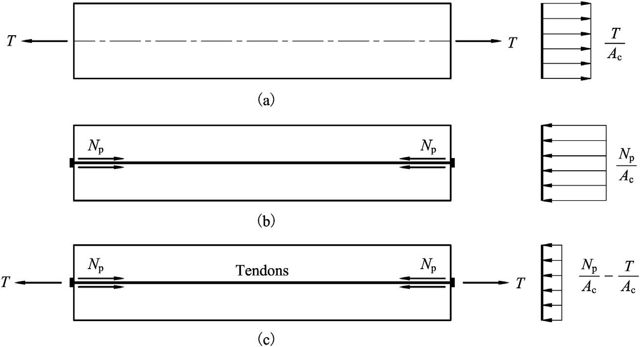
Considerareinforcedconcretemembersubjectedtoaxialtensionasshownin Fig.1.1A.Thetensilestressinconcretequicklyexceedsthetensilestrengthasthetension increases,withcrackingbecominginevitable.Ifthereinforcementsarereplacedby severalhigh-strengthsteelbarswithoutsideplasticpipeswhichareembeddedinside theconcretebeforecasting,highcompressionintheconcreteisgeneratedasthebars areanchoredattwomemberendsaftertheyarestretchedinhightensionwhentheconcreteattainssufficientstrength,asshownin Fig.1.1B.Inthisstate,thenormalstressof concreteinaprestressedsectionsubjectedtoaxialtensionisderivedas
where sc ¼ normalstressofconcrete.
sc ;p ¼ concretestressduetocompressiongeneratedbythestretchedsteelbars.
sc ;T ¼ tensilestressofconcreteduetoexternalaxialtension.
Np ¼ compressioninconcretetransferredfromthetensionedsteelbars.
T ¼ externalaxialtension.
Ac ¼ cross-sectionalareaofconcrete.
In Eq.(1.1),iftheintroducedcompressioninconcreteisgreaterthantheexternal tension,tensilestresswillnotoccurandcrackingwillbepreventedinthetensilemember.
Figure1.1 Schematicdiagramofthestressdistributionofanaxialtensilemember.
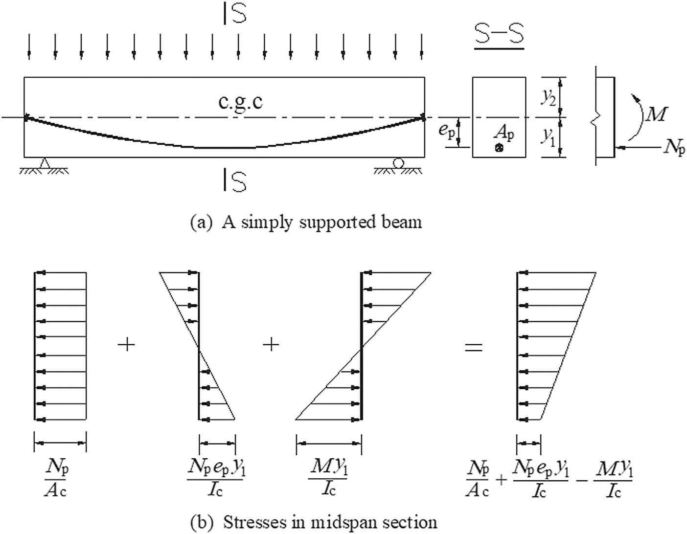
Considerasimplysupportedbeamsubjectedtoauniformlydistributedload.The beamisarrangedwithstretchedparabolicsteelwireswhichareanchoredatthebeam’ s ends,asshownin Fig.1.2.Thenormalstressinconcreteinthebottomface fiberat themidspanisgivenby
where sc ¼ stressinconcreteinthebottomface fiberatthemidspansection.
sc ;p ¼ compressivestressinconcreteinthebottomface fiberatthemidspansection causedbythestretchedwires.
sc ;M ¼ tensilestressinconcreteinthebottomface fiberatthemidspansectioncaused bytheuniformlydistributedload.
M ¼ bendingmomentatthemidspancausedbytheuniformlydistributedload.
Ac ¼ cross-sectionalareaofconcrete.
Ic ¼ momentofinertiaoftheconcretesection.
ep ¼ eccentricityofsteelwireswithrespecttothecenterofgravityoftheconcrete section(c.g.c.)atthemidspansection.
y1 ¼ distancefromthecenterofgravityoftheconcretesectiontothebottomedge.
Figure1.2 Stressdistributionatthemidspansectionofasimplysupportedbeam.
Similarly,iftheintroducedcompressivestressinconcretebythestretchedwiresis greaterthanthetensilestresscausedbytheuniformlydistributedload,therewillbe notensilestressatthetensionzone.
Theprestretchedsteelbarsandwiresarecalledprestressingsteelsorprestressingtendons,andthetensileforceinthetendonsiscalledtheprestressingforce.Thestress achievedinconcretebeforeitissubjectedtoaloadiscalledtheprestress.Inabroadsense, prestressedconcretereferstoconcreteinwhichprestressisachieveddeliberatelybefore service.Iftheprestressisgeneratedbythestretchedtendons,thecorrespondingprestressedconcretecanbetreatedasaparticularformofreinforcedconcrete.
Obviously,thetensilemember(Fig.1.1C)and flexuralmember(Fig.1.2A)arranged withprestressingtendonsareprestressedconcretestructures.Thecompressioninconcretetransferredfromtheprestressingforcenotonlychangestheinternalforcesofthe concretestructureinservicebutalsoaltersthestressesinsections.Tofullyorpartially eliminatethetensilestressinconcreteatserviceloads,thestressinthetendonsgenerated bystretchingshouldbehighenoughafterallstresslosseshavetakenplace.Therefore, hightensilestrengthmaterialsmustbeusedfortendons,meanwhile,thehighstrength oftendonscanbeutilizedfully.
1.2Thefunctionsofprestressorprestressingforce Althoughtheoriginalpurposeofintroducingprestressinconcretewastofullyeliminate thetensilestresses,thereareseveralotherfunctions.Takeareinforcedconcretesimply supportedbeamwitharectangularsectiononlysubjectedtotheself-weightasan example,asshownin Fig.1.3.Assumethattheloadintensityduetoself-weightof thebeamalongtheentirespanisconstant,thetensilestressinconcreteinthebottom face fiberatthemidspansectionisgivenby
Figure1.3 Schematicdiagramofasimplysupportedbeam.
where sc ;M ¼ tensilestressinconcreteinthebottomface fiberatthemidspansection duetotheself-weightofthebeam.
g ¼ loadintensityduetotheself-weightofthebeam.
h ¼ depthoftherectangularsection.
b ¼ widthoftherectangularsection.
I ¼ momentofinertiaofthereinforcedconcretesection, I ¼ 1 12 bh3 istaken approximately.
l ¼ effectivespan.
Ifcrackingisnotallowed,themaximumspanofthesimplysupportedbeamcanbe derivedfrom Eq.(1.3),as
where fct ;u ¼ tensilestrengthofconcrete.
fct ;u couldbethecharacteristictensilestrengthofconcrete, fctk ,inthe fip ModelCode andthedesigncodesinChina,ormodulusofruptureofconcrete fr ,intheACIcode.
Eq.(1.4) indicatesthatthesectiondepthwillincreasedramaticallyifalongerspan beamisbuiltwithoutcracking,sincethetensilestrengthofconcreteislowandit fluctuatesinasmallrange.Astheexternalloadsareexertedonthebeam,thesectiondepth hastobeincreasedmoredramatically.Thehugedepthnotonlygeneratesheavyselfweightresultinginanuneconomicalscheme,butalsooccupiesexcessivebuildingspace, indicatingthatreinforcedconcretecannotbeusedtobuildlong-spanbeams.Ifthe compressivestressinconcreteisintroducedinthetensionzone, Eq.(1.4) turnsinto
where sc ;p ¼ introducedcompressivestressinconcreteinthebottom fiberatthe midspansection.
Eq.(1.5) demonstratesthatthespancanincreaseeffectivelywiththeincreaseofintroducedcompressivestressincaseofkeepingthedepthunchanged,namely,ahigherspanto-depthratioisachievedintheprestressedconcretebeams.Meanwhile,theproportion ofself-weightintotaldesignloaddoesnotincreaseassharplywiththeincreaseofspanas thatinthereinforcedconcretebeam.Therefore,theprestressedconcretecanbeusedto buildlarge-span flexuralmemberswithlightself-weight.
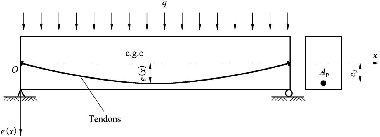
Thebendingmomentproducedbytheeccentricprestressingforce,asshownin Fig.1.2A,willgenerateupwardcamber.Iftheeccentricityformsaparabola(Fig.1.4), itcanbeexpressedas
Figure1.4 Aprestressedconcretebeamarrangedwithparabolictendons.
where ep ¼ eccentricityofthetendonswithrespecttothecenterofgravityofthe concretesection.
l ¼ effectivespan.
x ¼ distancefromtheleftsupporttothesectionunderconsideration.
Thetotalinternalforcesinasectionoftheprestressedconcretebeamsubjectedtoa uniformlydistributedloadaregivenby
where qðxÞ¼ bendingangleofthetendonswithrespecttothebeam’saxis.
q ¼ uniformloadduetotheself-weightofthebeamandexternalloads.
Np ¼ prestressingforce.
M ðxÞ¼ bendingmomentinasection.
V ðxÞ¼ shearforceinasection.
N ðxÞ¼ axialforceinasection.
Assumethatthemodulusofelasticityofconcreteisconstant,thedeflectionatmidspancanbederivedby
¼ Z
where EI ¼ sectional flexuralrigidity.
Mmid ¼ bendingmomentatmidspanduetouniformlydistributedload.
Eq.(1.10) demonstratesthattheeccentricprestressingforcecaneffectivelyadjustthe deflectionofthebeambyalteringtheprestressingforce Np anditseccentricity ep , respectively.
Ingeneral,theintroducedprestressorprestressingforcebearsthefollowingbasic functions:
(1) Toimprovetheworkingperformanceofconcretestructuresbyactivelycounterbalancingfullyorpartiallythetensilestressinconcretecausedbytheserviceloads.
(2) Toenableconcretetobeusedtobuildlong-spanstructureswithlightself-weight.
(3) Toactivelyadjustthedeflectionofthe flexuralmembersbyalteringtheprestressing forceanditseccentricity,respectively.
(4) Toenablehigh-strengthmaterialstobeemployedefficientlyandeconomicallyin concretestructures.
1.3Prestresslevel Theprestresslevel,knownasthedegreeofprestressing,referstotheratioofprestressingcausedcompressivestressinconcreteintheextremetension fibertoload-causedtensile stress,expressedas
where sc ;p ¼ compressivestressinconcreteintheextreme fiberinthetensionzone generatedbytheprestressingforce.
sc ;l ¼ tensilestressinconcreteintheextreme fiberduetotheserviceloads.
For flexuralmembers,theprestresslevelcanbeexpressedas
(1.12)
where M0 ¼ decompressionmoment,themomentthateliminatestheprestressingcausedcompressivestressinconcreteintheextremetension fibertozero.
M ¼ bendingmomentcausedbytheserviceloads.
Foraxialtensionmembers,theprestresslevelcanbeexpressedas
(1.13)
where N0 ¼ decompressionaxialforce,theforcethateliminatestheprestressing-caused compressivestressinconcretetozero.
N ¼ axialforcecausedbytheserviceloads.
Theprestresslevelisanimportantindexindesign,whichcanbeusedtocontrolthe concretestressandcracking.Therewillbenotensilestressinthetensionzoneatservice
loadswhen lP1,whiletensilestressoccurswhen l < 1,andthecrackingevendevelops whenthetensilestressexceedsthetensilestrengthofconcrete.Therefore,theprestress levelmakesthereinforcedconcreteacontinuousspectrumwhichcanbegroupedinto thefollowingthreecategories:
ClassI-fullyprestressedconcrete(FPC), lP1.
ClassII-partiallyprestressedconcrete(PPC),0 < l < 1.
ClassIII reinforcedconcrete(RC), l ¼ 0.
1.4Classificationofprestressedconcrete Theprestressedconcretecanbeclassifiedbystressingmethods,prestresslevel,crackcontrol,bondingcondition,andthepositionoftheprestressingtendonsintheconcrete section.
1.4.1Classificationbystressingmethods
Accordingtotheprocessofcastingconcreteorstretchingtendons firstduringconstruction,theprestressedconcretestructuresareclassifiedintopretensionedandposttensionedstructures.Theformerreferstothestructuresthatthetendonsarestretched beforecastingconcrete,whilethetendonsarestretchedandanchoredaftertheconcrete iscastandhardensenoughinthelatter.
1.4.2Classificationbyprestresslevel
Astheprestresslevelisexpressedby Eqs.(1.11) (1.13),theprestressedconcretecanbe classifiedintofullyprestressedconcretewhen lP1andpartiallyprestressedconcrete when0 < l < 1.
Fullyprestressedconcreteisbroadlyusedinhighwaybridges,railwaybridges,and civilandindustrialbuildings.Forlong-spanbridgesandthosestructuresinwhich crackingisnotallowed,suchasoiltanksandnuclearvessels,fullyprestressedconcrete isoneofthemostpreferablebuildingmaterials.Sincecrackingisavoidedintheservice period,fullyprestressedconcretebearshighfatigueresistance,makingitwidelyusedin railwayandhighwaybeams,cranebeamsinfactories,andotherstructuresthatcomeunderrepeatedloading.
High-strengthsteelwiresandstrandswithoutobviousyieldpointsarewidelyusedin prestressedconcrete.Toimprovethestructuralductilityinearthquake-proneareas,a greatquantityofreinforcingsteels(nonprestressingsteels)arecommonlyarrangedin theconcretetoreplacepartoftheprestressingtendons,inthiscondition,tensilestress inconcreteorcrackinginthetensionzoneisallowedatserviceloads.Thesepartiallyprestressedconcretestructurescanbeclassifiedintotwotypes,ClassAandClassBinthe CodeforDesignofHighwayReinforcedConcreteandPrestressedConcreteBridgesandCulverts (JTG3362-2018).ForClassA,themaximumtensilestressinconcreteinthetension
zonecannotexceedtheallowablevaluesprescribedinthecode.ForClassB,crackingis allowedwhilethecrackwidthshouldbecontrolledtoalimitedvalueprescribedinthe code.
1.4.3Classificationbythelevelofcrackcontrol
Accordingtothelevelofcrackcontrolinserviceabilitylimitstate,the Concretestructure designcode (GB50010-2010)and Prestressedconcretestructuredesigncode (JGJ369 2016) stipulatethattheprestressedconcretecanbeclassifiedintothefollowingthreecategories:
ClassI notensilestressinconcreteinthetensionzoneisallowedintheservice period.
ClassII limitedtensilestressinconcreteinthetensionzoneisallowedintheservice period.
ClassIII crackingisallowedwhilethemaximumcrackwidthcannotexceedthe valuesspecifiedinthecode.
Threeclassesofthebehaviorofprestressed flexuralmembersaredefinedintheACI code.ClassUmembersareassumedtobehaveasuncrackedmembers,ClassCmembers areassumedtobehaveascrackedmembers,andthebehaviorofClassTmembersis assumedtobeintransitionbetweenuncrackedandcracked.
1.4.4Classificationbybondingconditionbetweentheprestressingtendons andtheconcrete
Thebondedprestressedconcretereferstothoseinwhichtheprestressingtendonsarearrangedintheconcreteandbondtogether,whiletheprestressingtendonsdonotcontact theconcretedirectlyintheunbondedprestressedconcrete.Iftheunbondedprestressing tendonsarearrangedoutsideoftheconcreteinastructure,thecorrespondingstructureis calledtheexternallyprestressedconcretestructure.
1.5Prestressedversusreinforcedconcrete Comparedtoreinforcedconcrete,prestressedconcretebearsthefollowingadvantages.
1.5.1Highcrackresistance Thecompressivestressinconcretegeneratedbythelongitudinalprestressingforcecan completelyorpartiallyeliminatethenormaltensilestresscausedbytheserviceloads. Inaddition,theprincipaltensilestressinconcreteduetotheserviceloadscanbeeffectivelyreducedordeletedbytheinclinedcompressiongeneratedbythebentuplongitudinalprestressingtendonsandverticalprestressingtendonsinthewebs.Therefore,there ishighcrackresistanceinthetensionzoneand flexural-shearzoneinprestressedconcrete structures.
1.5.2Highshearresistance
Theverticalforcegeneratedbythebentuplongitudinalprestressingtendonsandvertical prestressingtendonscounterbalancescompletelyorpartiallytheshearforcecausedbythe designload,resultinginhighresistanceforshearforceinservice.Ontheotherhand,the highshearbearingcapacityhelpstoreducethewebthicknessintheprestressedconcrete structures,leadingtolighterself-weight.
1.5.3Highdurability
Inafullyprestressedconcretestructure,crackingisnotallowed.Inapartiallyprestressed concretestructure,althoughthecrackingmayoccurunderthemostunfavorablelive load,thecrackswillclosemostofthetime.Hence,thelowchanceofdirectlybeing incontactwithmoistureandairpreventsthesteelfromcorroding,therebyhighdurabilityisachievedinprestressedconcrete.
1.5.4Highfatigueresistance
Thefatigueresistanceoftheconcretestructuresdependsmainlyonthestressamplitudein tensilereinforcement.Intheprestressedconcretestructures,thevariationofstresscaused bytheliveloadisrelativelylowcomparedtotheexistingstressintendonsintheservice period,thislow fluctuationgivesprestressedconcretestrongfatigueresistance.
1.5.5Abilitytocontrolthedeflectionactively
Accordingto Eq.(1.10),thedeflectionofa flexuralmembercanbeadjustedeffectively byalteringtheprestressingforceanditseccentricity,respectively.Thisadvantagenot onlymakesitpossibleto flexiblysettheprestressingtendonsaccordingtothestructure characteristicsandcross-sectionformsinthedesignofnewstructuresbutalsocanadjust thedeflectionofexistingstructuresbyaddingexternalprestressingtendons,which broadenstheapplicationoftheprestressingtechnology.
1.5.6Abilitytobuildlong-spanstructureswithlighterself-weight
Asshownin Eq.(1.5),ahigherspan-to-depthratioiseasilyachievedintheprestressed concretebeams.Inaddition,thecrackinganddeflectionofthebeamcanbecontrolled effectivelybyadjustingthelongitudinalprestressingforceanditseccentricityandtheverticalprestressingforceratherthanbyincreasingthesectiondepth,makingprestressed concretesuitableforbuildinglong-spanstructures.Atpresent,prestressedconcretehas strongcompetitivenessinbuildingbridgeswithspansfrom30to300m(Fig.1.5).
1.5.7Efficientutilizationofhigh-strengthmaterials
Inaprestressedconcretemember,thetendonsmustbestretchedtoaveryhighstressso thatthepermanentstressintendonsintheserviceperiodcanbekeptatadesiredhigh
