Workbook for Diagnostic Medical Sonography: A Guide to Clinical Practice Obstetrics and Gynecology (Diagnostic Medical Sonography Series) 4th Edition, (Ebook PDF)
Aubrey J. Rybyinski, BS, RDMS, RVT Lead Technologist/Technical Director Navix Diagnostix Thunton, Massachusetts
Kellie A. Schmidt, BS, RDMS, RVT, RDCS Clinical Instructor Division of Ultrasound and Prenatal Diagnosis University of Colorado Hospital Aurora, Colorado
Dana C. Walker, BS, RDMS, RVT Radiology Manager-Ultrasound University of Wisconsin Hospitals and Clinics Madison, Wisconsin
Michelle Wilson, EdD, RDMS, RDCS Clinical Sonographer/Educator Kaiser Permanente Napa, California
REVIEWERS
Brent Bereska. ARDMS. RDMS, RDCS
Sonography Canada: CRGS, CRCS
Northern Alberta Institute of Technology Edmonton, Canada
Martie Grant, ARDMS
General and Cardiac and Breast Sonography Canada: Generalist and Cardiac
Northern Alberta Institute of Technology Edmonton, Canada
Cambridge College of Healthcare and Technology Atlanta, Georgia
The fourth edition of Diagnostic Medical, Sonogmphy: Abdomen and Superficial Structures is updated to reflect the major developments that have occurred since the last edition. Educators and colleagues encouraged us to produce a fourth edition to incorporate new advances used to image, to refresh the foundational content, and to continue to provide information that recognizes readers have diverse backgrounds and experiences. The result is a textbook that can be used as either an introduction to the profession or a reference for the profession. The content lays the foundation for a better understanding of anatomy, physiology, and pathophysiology to enhance the caregiving role of the sonographer practitioner, sonographer, sonologist, or student when securing the imaging information on a patient.
The first chapter introduces terminology on anatomy, scanning planes, and patient positions. Adopting universal terminology permits every sonographer to communicate consistent information on how he or she positioned the patient, how he or she scanned the patient, and how anatomy and pathology are sonographically represented.
The next four sections are divided into specific content areas. Doing this allowed the contributors to focus their attention on a specific organ or system. This simulates
application in that while scanning, the sonographer investigates the organ or system, moves systematically to the next organ or system, and completes the examination by synthesizing all the infonnation to obtain the total picture.
We made every attempt to produce an up-to-date and factual textbook while presenting the material in an interesting and enjoyable format to capture the reader's attention. To do this, we provided detailed descriptions of anatomy, physiology, pathology, and the normal and abnormal sonographic representation of these anatomic and pathologic entities with illustrations, summary tables, and images, many of which include valuable case study information.
Our goal is to present as complete and up-to-date a text as possible, while recognizing that by tomorrow, the textbook must be supplemented with new information reflecting the dynamic sonography profession. With every technologi.c advance made in equipment, the sonographer's imagination must stretch to create new applications. With the comprehensive foundation available in this book, the sonographer can meet that challenge.
Diane M. Kawamura 'Cm.ya D. Nolan
ACKNOWLEDGMENTS
Aspecial recognition to Bridgette Lunsford, co-editor of the third edition. As a sonographer, educator, and author, Bridgette's contributions made it possible to have made the giant leap that occurred between the second and the third editions. While preparing the fourth edition, we appreciated the support, ideas, and collaboration of Anne Marie Kupinski, Susan Stephenson, and Julia Dmitrieva as we worked on the three volumes of Diagnostic Medical Sonogmphy. Their input and ideas were a significant contribution to the project.
Our thanks and gratitude go to all the contributors of the fourth edition who gave of their expertise, time, and energy, updating the content with current information to use in obtaining a more accurate imaging examination for our patients.
The image contributions became treasured moments. We thank the many sonographers and physicians for their assistance. A special thank you and recognition for ongoing support in image acquisition goes to Taco Geertsma, MD, Ede, the Netherlands, at Ultrasoundcases.info and Siemens
Medical Solutions USA, Inc. Thank you to the contributors of the third edition: Philips Medical Systems, Bothell, Washington; GE Healthcare, Wauwatosa, Wisconsin; Joe Anton, MD, COchin, India; Dr. Nakul Jerath, Falls Church, Vuginia; and Monica Bacani and Rechelle Nguyen at Nationwide Children's Hospital in Columbus, Ohio.
Many thanks to all the production team at Wolters Kluwer, who helped edit, produce, promote, and deliver this textbook. We especially thank in the development of this edition Jay Campbell, acquisitions editor; Heidi Grauel, freelance product manager; Jennifer Clements, art director; and John Larkin, Editorial Coordinator, for their patience, follow-through, support, and encouragement.
'lb our colleagues, students, friends, and family, who provide continued sources of encouragement, enthusiasm, and inspiration-thank. you.
Diane M. Kawamura
Tanya D. Nolan
USING THIS SERIES
The books in the Diagnostic Medi.cal Sonography series will help you develop an understanding of specialty sonography topics. Key learning resources and tools throughout the textbook aim to increase your understanding of the topics provided and better prepare you for your professional career. This User's Guide will help you familiarize yourself with these exciting features designed to enhance your learning experience.
Chapter Objectives
Measurable objectives listed at the beginning of each chapter help you understand the intended outcomes for the chapter, as well as recognize and study important concepts within each chapter.
Glossary
Key terms are listed at the beginning of each chapter and clearly defined, then highlighted in bold type throughout the chapter to help you to learn and recall important terminology.
Pathology Boxes
Each chapter includes tables of relevant pathologies, which you can use as a quick reference for reviewing the material.
· --
• """" l!llftNdulor pbr
• FolkWr thyroid carc:1 (rwe)
• ThJn>ldltil
• ... c:.- .rs--, ..,,._,,...11111111
• S--of---ofthyrold hormone bl' eclrlplctllJr'Old-flll Ill_IOI_
Critical Thinking Questions
Throughout the chapter are critical thinking questions to test your knowledge and help you develop analytical skills that you will need in your profession.
Iii Nmlllllb'N-. moo., dmviti.plll1illrl5.Gf.-.inlphl.-.n:itm bri&H=Ganuinqm. crni..b!'Wfrttlwin::irmll dllmhllln.ldll18!1d iadYlldmWtr
ANAltJMIC DERNITIONS 1llt __......, ..
-Wllllll'IFRW-ntbm--ll<ID
CRITICAL THINKING QUESTIONS
l. A Doppler apeclral anafylil of the DOl'lllBl SMA mmla a cbaracterlst1c pattl!m associated with a hfgbly reliltant YUCUlar bed. There • a 8harp rite in ftow during fY9fO)e and a rapid falloff clwiD8 diutole with IeWISi!l a1 the ftow below the bueliDe. What doell lhlll dwactEl'iltk: pattern descrlbel
Resources the Poinf
You will also find additional resources and exercises on thePoint, including a glossary with pronunciations, quiz bank, sonographic video clips, and weblinks. Use these interactive resources to test your knowledge, assess your progress, and review for quizzes and tests.
Introduction I
DIANE M. KAWAMURA
PART ONE I ABDOMINAL SONOGRAPHY
2 The AbdominaJ Wall and Diaphragm 13 TERRI L. JURKIEWICZ
3 The Peritoneal Cavity 41 JOIE BURNS
4 Vascular Structures 59 AUBREY J. RYBYINSKI
5 The Liver IOI M. ROBEIU DE JONG
6 The GaJlbladder and Biliary System 171 TERESA. M. BIEKER
7 The Pancreas 213 KEWEA 50-IMIDT
8 The Spleen 229 TANYAD. NOLAN
9 The Gastrointestinal Tract 247 llAABAAA HALL-TERRACCIANO
I 0 The Kidneys 271 SARAM. BAKER I DANAC. WALKER
11 The Lower Urinary System 335 DANA C. WALKER. I SARA M. WER
12 The Prostate Gland 357 GEORGE M. KENNEDY->NTILLON
13 The AdrenaJ Glands 377
DARLA MATTHEW
14 The Retroperitoneum -405
JOIE BURNS PART TWO
15 The Thyroid Gland, Parathyroid Glands, and Neck 421 DIANE M. KAWAMURA
The Pediatric Abdomen 611 SASHA P. GORDON
The Pediatric Urinary System and Adrenal Glands 655 ALYSSA FREDERICK
The Neonatal Brain 687 MONICA M. Bll.CANI
Spine 715
Joint
Organ Transplantation 739
KEYlN D. EVANS 25 Point-of-Care Sonography 757
J. P. MORELAND I MICHELLE WILSON 26 Foreign Bodies 779 TIMS. GIBBS
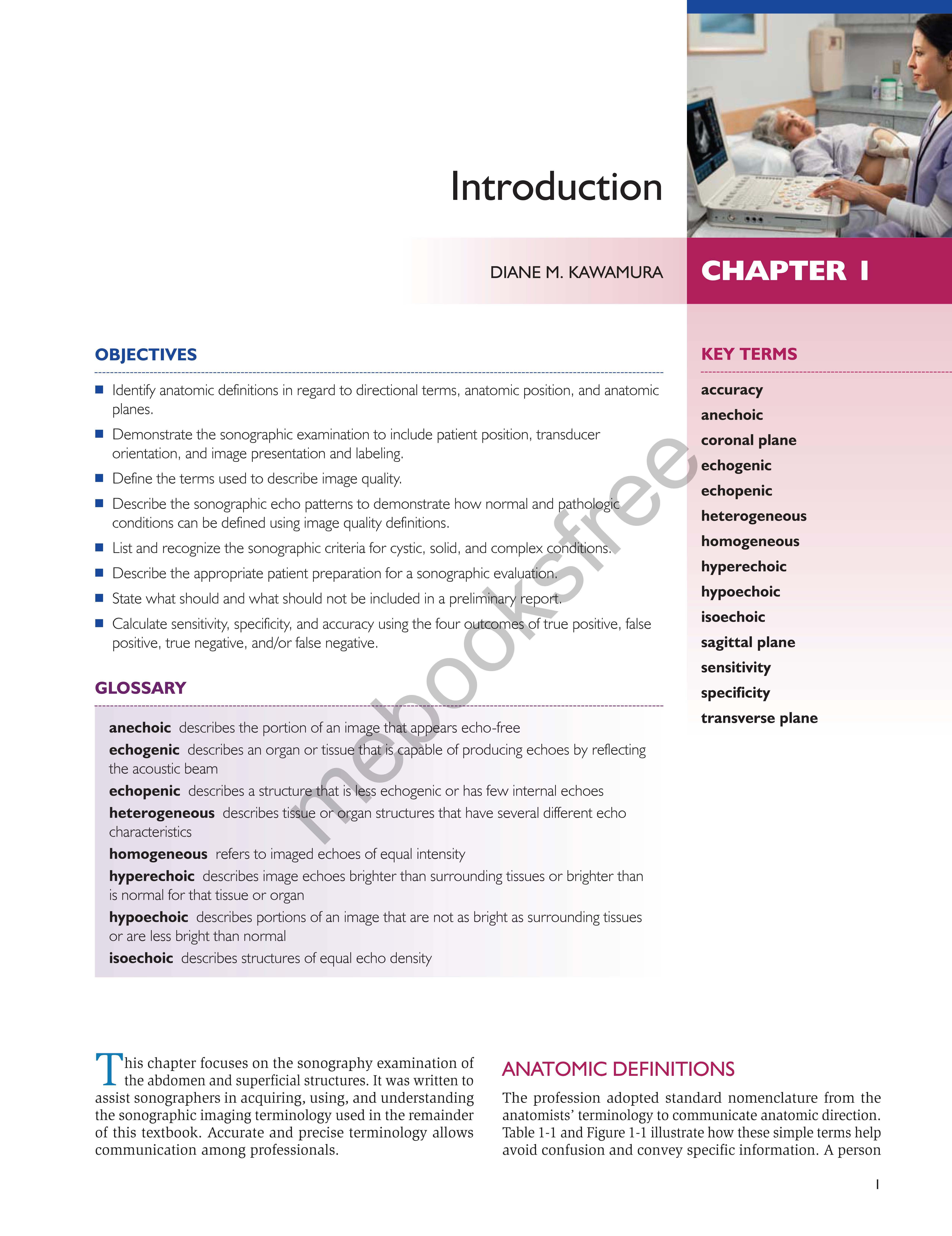
Identify anatomic definitions in regard to directional terms, anatomic position, and anatomic planes.
Demonstrate the sonographic examination to include patient position, transducer orientation, and image presentation and labeling.
Define the terms used to describe image quality.
Describe the sonographic echo patterns to demonstrate how normal and ~ tholagi c conditions can be defined using image quality definitions
List and recognize the sonographic criteria for cystic, solid, and complex co 0 1tions.
Describe the appropriate patient preparation for a sonographic evalua 10n.
State what should and what should not be included in a prelimi ~ ry ejJO
Calculate sensitivity, specificity, and accuracy using the four o tco es of true positive, false positive, true negative, and/or false negative.
GLOSSARY
anechoic describes the portion of an image that appears echo-free
echogenic describes an organ or tissue that is capable of producing echoes by refiecting the acoustic beam
echopenic describes a structure-that is less echogenic or has few internal echoes heterogeneous describes tissue or organ structures that have several different echo characteristics
homogeneous refers to imaged echoes of equal intensity
hyperechoic describes image echoes brighter than surrounding tissues or brighter than is normal for that tissue or organ
hypoechoic describes portions of an image that are not as bright as surrounding tissues or are less bright than normal
isoechoic describes structures of equal echo density
This chapter focuses on the sonography examination of the abdomen and superficial structures. It was written to assist sonographers in acquiring, using, and understanding the sonographic imaging terminology used in the remainder of this textbook. Accurate and precise terminology allows communication among professionals.
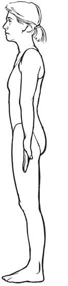
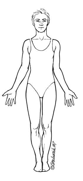
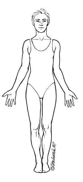
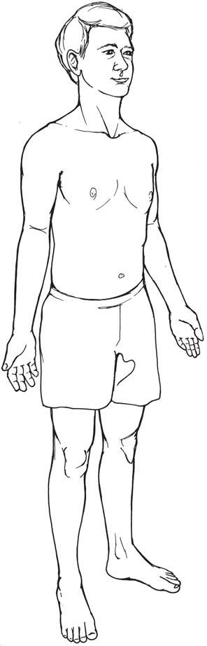
The profession adopted standard nomenclature from the anatomists' terminology to communicate anatomic direction Table 1-1 and Figure 1-1 illustrate how these simple terms help avoid confusion and convey specific information. A person
TABLE 1-1 Dlrectlonal Terms 'llrm
Superior (cranial)
Inferior (caudal)
Anterior (ventral)
Posterior (dorsal)
Medial
Lateral Ipsilateral
Contralateral
Proximal
Distal
Superficial Deep
Daftnldan
Toward the head, doser to the head, the upper portion of the body, the upper part d a structure, or a structure higher than another structure
Toward the feet, away from the head, the lower portion of the body. toward the lower part of a structure, or a structure lower than another structure
Toward the front or irt the front of the body or a strud.\Jre in front of another strud.\Jre
Toward the back or the bade d 1he body or a structure behind anotiier structure
Toward the middle or mid line of the body or the middle of a structure
Away from the middle or the midline of the body or perlaining to the side
Located on the same side of1he body or afecting the same side of the body
Eample
The left adrenal gland is superior to the left kidney
The lo>.Ver pole d each kidney is inferior to the upper pole
The main portal vein is anterior to 1he inferior venacava
The main portal vein is posterior to the common hepatic artery
The middle vein is medial tD the ri.!trt hepatic vein
The ri.!trt lciciiey is lateral tD the inferior vena caw.
The gallbladder and right kidney are ipsilateral
Located on the opposite side of1he body or affecting the opposite sided The pancreatic: tail and pancreatic head are the body contralateral
Ooser to the attachment of an extremity to the trunk or 1he ori_i;n of a The abdominal aorta is proximal to the body part bifurcation of the iliac arteries
Farther from the attachment of an extremity to 1he trunk or the origin of a The iliac arteries are distal to the abdominal body part aorta
Toward or on the body surface or external
Away from the body surface or internal
Anterior Ventral
The thyroid and breast are consiclered superficial strud.\Jres
The peritoneal organs and great vessels are deep strudures
Cranial Cephalic
in the conventional an.atomic position is standing erect, feet together, with the arms by the sides and the palms and face directed forward, facing the observer. When sonographers use directional terms or descnbe regions or anatomic planes, it is assumed that the body is in the anatomic position. There are three standard anatomic planes (sections) that are imaginary flat surfaces passing through a body in the standard anatomic position. The sagittal plane and coronal plane follow the long axis of the body and the transverse plane follows the short axis of the body1 (Fig. 1-2).
FIGURE 1-1 Anatomic: planes. The standard anatomic: position is use<J to depict 1he three imafjnary anaromic: flat surface planes. Both and coronal planes !>i1S$1tirough ttie long axis and the 1ransvel'$C plane passes through the short axis.
The word sagittol. literally means "flight of an arrow"' and refers to the plane that runs vertically through the body and separates it into right and left portions. The plane that divides the body into equal right and left halves is referred to as the median sagittal or midsagittal plane. Any vertical plane on either side of the midsagittal plane is a parasagittal. plane (para means "alongside of"). In most sonography cases, the term sagittal usually implies a parasagittal plane unless the term is specified as median sagittal or midsagittal. The coronal plane runs vertically through the body from right to left or left to right, and divides the body into anterior and posterior portions. The transverse plane passes through the body from anterior to posterior and divides the body into superior and inferior portions and runs parallel to the surface of the ground.
SCANNING DEFINITIONS
Patient Position
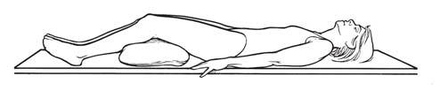
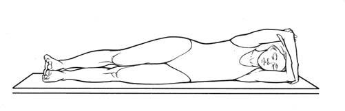
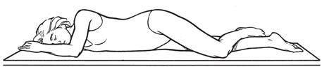
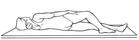
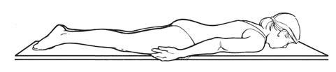
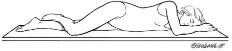
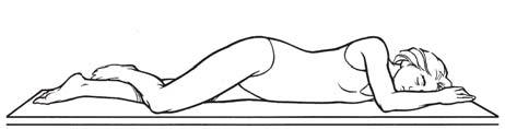
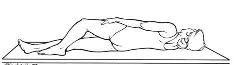
Positional terms refer to the patient's position relative to the surrounding space. For sonographic examinations, the patient position is described relative to the scanning table or bed (Table 1-2; Fig. 1-3). In clinical practice, patients are scanned in a recumbent, semierect (reverse 'Jl'endelenburg or Fowler), or sitting position. On occasion. patients may be placed in other positions, such as the lrendelenburg (head lowered) or standing position, to obtain unobscured images of the area of interest. Sonographers frequently convey information on patient position and transducer placement simultaneously. This terminology most likely was adopted from radiography, where it describes the path of the X-ray beam through the patient's body (projection). which results
TABLE 1-2 Patient Positions
'R9rm DelCl'lptlon
Decubltu1 or The act d lying dOIMl. The adjective Recumbent before 1he word desaibes the most dependent body surface
Supine or dorsal
Prone or ventral
RLD
LLD
Oblique
RPO
LPO
RAO
LAO
Lying on 1he bac:k
Lying face cbNn
Lying on 1he right side
Lying on 1he left side
Named for the body side dosest to the scanning table
Lying on 1he right posterior surface, the left posterior surface is elevated
Lying on 1he left posterior surface, 1he right posterior surface is elevated
Lying on 1he right anterior surface, the left anterior surface is elevated
Lying on the left anterior surface, the right anterior S\Jrface is elevated
LAO, left anterior oblique; LLD, left lateral de<:ubitus; LPO, left posterior oblique; RAO. right anterior oblique: RlD. right lareral de<:ubitus; RPO. right posterior oblique.
FIGURE I·3 Patient positioos. The various patient positions depicted in the illustration correlate with the descriptions in Table 1-2. lAO, left anterior oblique; I.PO, left posterior oblique: RAO, right anterior oblique: RPO. right posterior oblique.
in a radiographic image {view). There is no evidence in the literature that this nomenclature has been adopted as a professional standard for sonographic imaging. Describing sonograms using the terms projection or view should be avoided. It is more accurate to describe the sonographic image stating the anatomic plane visualized, which is due to the transducer's orientation (i.e., transverse). A more specific description of the image would include both the anatomic plane and the patient position (i.e., transverse, oblique).
Transducer Orientation
The transducer's orientation is the path of the insonating sound and the path returning echoes is viewed on the monitor. 'Itansducers are manufactured with an indicator (notch, groove, light) that is displayed on the monitor as a dot, arrow, letter of the manufacturer's insignia, and so forth. Scanning plane is the term used to describe the transducer's orientation to the anatomic plane or to the specific organ or structure. The sorwgraphi.c image is a representation of sectional anatomy. The term plane combined with the adjectives sagittal, parasagittal, coronal, and transverse describes the section of anatomy represented on the image (e.g., transverse plane).
Because many organs and structures lie oblique to the imaginary body surface planes, sonographers must identify sectional anatomy accurately to utilize a specific organ and structure orientation for scanning surfaces. The sonography imaging equipment provides great flexibility to rock, slide, and angle the transducer to obtain sectional images of organs oriented obliquely in the body. For example, to obtain the
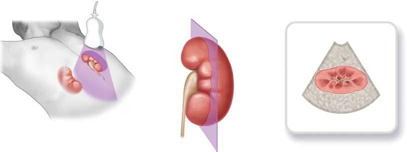
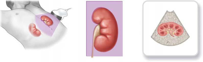
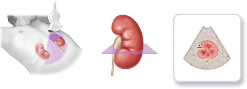
long axis of an organ, such as the kidney, the transducer is oblique and is angled off of the standard anatomic positions: sagittal, parasagittal, coronal, or transverse plane. Sonographers frequently use the terms sagittal. or parasagittal to mean longitudinal in depicting the anatomy in a long-axis section. Although some images in this text are labeled sagittal or parasagittal, they are, in fact, longitudinal planes because the image is organ specific. For organ imaging, transverse planes are perpendicular to the long axis of the organ, and longitudinal and coronal planes are referenced to a surface. All three planes are based on the patient position and the scanning surface (Fig. 1-4A-C).
Image Presentation
When describing image presentation on the display monitor, the body, organ, or structure plane terminology, coupled with transducer placement. provides a very descriptive portrayal of the sectional anatomy being depicted. CUrrent flexible, freehand scanning techniques may lack automatic labeling of the scanning plane. With the free-hand sc.anning technique, quantitative labeling may be limited, which means reduced image reprodUCJ.'bility from one sonographer to another sonographer. Sonographers usually can select from a wide array of protocols for image annotation or em.ploy postprocessing annotation. This is extremely important when the image of an isolated area does not provide other anatomic structures for a reference location. 1b ensure consistent practice, sonographers must correctly label all sonograms. With today's equipment, standard presentation and labeling is easily achieved along with additional labeling of specific structures and added comment.
Supine Prone
Lateral
Oblique
RAO LAO
LPO
RPO
Longitudinal section
Coronal plane
Coronal section
Sonogram
Anterior
Posterior
Sonogram
Tulnswrae plane
Tulnswrae section
Sonogram
Anterior
Posterior
FIGURE 1-4 Transduair orientation. A:. A parasagittal plane provides a longitudinal section of the kidney on the sonogram. B: The coronal plane provides a coronal section on the sonogram. C: The trar\Sllerse plane provides a tranwerse section on the sonogram. The sonogram is the image the sonographer observes on 1he monitor.
The anterior, posterior, right, or left body surface is usually scanned in the sagittal (parasagittal), coronal, and transverse scanning planes. For organ or structure imaging, these same body surfaces are scanned with different angulations and obliqueness of the transducer to obtain longitudinal, coronal. or transverse scanning planes. With few exceptions. the transducer at the scanning surface is presented at the top of the image. 1.2 Images obtained using an endovaginal probe are usually flipped so that they are presented in the more traditional transabdominal transducer orientation, whereas images obtained using an endorectal probe are presented in the transducer-organ orientation. With the neonatal head (neurosonography, neurosonology), the superior scanning surface is presented at the top of the image when the transducer is placed on the neonate's head.
These six scanning surfaces, anterior or posterior, right or left. endocavitary (vaginal or rectal), and the cranial fontanelle coupled with three anatomic planes (sagittal, coronal, and transverse) produce a combination of 14 dif· ferent image presentations.
Longitudinal: Sqittal Planes
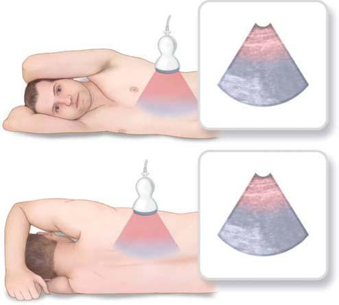
When scanning in the longitudinal, sagittal plane, the transducer orientation sends and receives the sound from either an anterior or posterior scanning surface. For a longitudinal plane, the transducer indicator is in the 12 o'clock position to the organ or to the area of interest. This always places the superior (cephalic} location on the image. From either the anterior or posterior body surface, the patient can be scanned in either erect, supine, prone, or an oblique position. The
Right
image presentation includes either the anterior or posterior, the superior (cephalic), and the inferior (caudal) anatomic area being ex:amined.1•2 (Fig. 1-SA). Because the longitudinal, sagittal image presentation does not demonstrate the right and left lateral areas, adjacent areas can be evaluated and documented with transducer manipulation, changing the transducer orientation, or changing the patient position. 2
Lonsitudinal: Coronal Planes
When scanning in the longitudinal, coronal plane, the transducer orientation sends and receives the sound from
either the right or left scanning surface. Because the transducer indicator is in the 12 o'clock position to the organ or to the area of interest, the superior (cephalic) location is always imaged. From either the right or left body surface, the patient can be scanned in either an erect, decubitus, or an oblique position and the image presentation includes either the left or right, the superior (cephalic), and the inferior (caudal) anatomic area being examined1.2 (Fig. 1-SB}. Because the longitudinal, coronal image presentation does not demonstrate the anterior or posterior areas, adjacent areas can be evaluated and documented with transducer
Anterior
FIGURE 1-5 Image presentl.tions. k Longitudinal, sagittll plane. With 1he patient being scanned from either 1he anterior or 1he posterior surface with or without obliquity. the image seen on the monitor demonstrates the scanning wrface (anterior or posterior) and the wperior (cephalic) and inferior (caudal) area being examined. 8: Lon,P!clinal, ooronal plane. Wrth the patient scanned from either the right or left surface with or without obliquity, the image seen on the monitor demonstrates the surface (right or left) and the superior (cephalic) ind inferior (caudal) areas being examined. C: Transverse plane, anterior or posterior S\Jrfaae. Wth the patient being scanned from either the anterior or posterior surface with or without obliquity. the image seen on the monitor demonstrates the scanning surface (anterior or posterior) and the right and left areas being examined. 0: Transverse plane, right or left wrface. Wilh 1he patient being scanned from either the right or the left surface wi1h orwittlout obliquity. the image seen on the monitor demonstrates the scanning surfate (right or left) and the anterior and posterior areas being examined.
manipulation, changing the transducer orientation, or changing the patient position.1
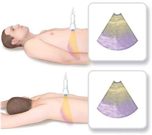
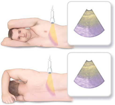
Transverse Plane: Anterior or Posterior Surface
Using the anterior or posterior surface, the transducer orientation for a transverse plane places the transducer indicator in the 9 o'clock position on either the anterior or posterior surface to the organ or to the area of interest. The right and left location is always imaged. From either the anterior or posterior surfaces, the patient can be scanned in either an erect, decubitus, or an oblique position. The image presentation includes either the anterior or posterior and the right and left anatomic area being examined1..2 (Fig. 1-SC).
cauclalllnferior
'I: l: s .2' to a:
caudal/Inferior
Transverse Plane: Right or Left Surface
Using the right or left surface, the transducer orientation for a transverse plane places the transducer indicator in the 9 o'clock position on either the right or left surface to the organ or to the area of interest. From either the right or left surfaces, the patient can be scanned in either an erect, decubitus, or an oblique position. The image presentation includes either the right or left and the anterior and posterior anatomic area being examined1..2 (Fig. 1-SD).
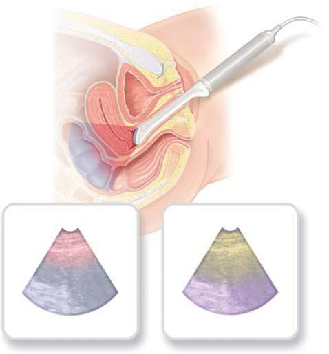
Endovaginal Planes
The patient is in the supine position for endovaginal imaging. The image presentation does not change if the system
Posterior (Rectum) Posterior (Rectum)
Cephalic/Superior
Cephalic/Superior
Sagittal Coronel
Anterior Anterior
Saglttal Coronel orTranswrse
Ceudalllnferlor Caudal/Inferior
FIGURE 1-5 {CDntinued) E: Endovaginal planes. The image preserrtrtion on 1t1e left illustrates a sat')ttal plane and 1t1e one on the right is the coronal plane. On either presentation, the apex of the image seen on the monitor corresponds t.o the il'\ilt.omy dose st to the faced the transducer: F: Endomc:IAI planes. The image presentdioo on the left illustral:es a sagill2l plane and the one on 1t1e right is 1t1e transverse or coronal plane. On either presentation, 1t1e apex of the image seen on the bottom c:J 1t1e monitor corresponds to the anatomy closest to the face of the transducer. G: Cranial fontanelle planes. With the patient being scanned from either the anterior or the posterior surface wi1t1 or without obliquity. the image seen on the monitor demonstrates 1t1e scanning surface (anterior or posterio1' and the superior (cephalic) and inferior (caudal) areas being examined.
employs either an end-firing or an angle-firing endovaginal transducer. For the sagittal Oongitudinal) plane, the transducer is placed at the caudal end of the body with the indicator in the 12 o'clock position. Orientations of both the endovaginal sagittal and the translabial transducer produce the same image presentation. The inferior (caudal) anatomy is presented at the top of the monitor with visualization of the anterior and posterior anatomic areas.
The coronal plane is obtained with the transducer at the caudal end of the body and the indicator in the 9 o'clock position. The top (apex) of the image is the inferior (caudal) area and the right and left anatomic areas can be visualized on the display monitor. The coronal plane is sometimes described using an older description reference to the transverse plane1 (Fig. 1-SE).
Endorectal Planes
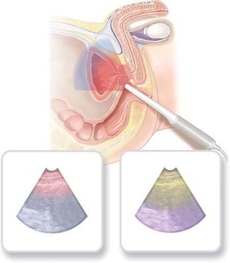
The patient is most often in a left lateral decubitus position for placement of either the end-firing or the bi-plane endorectal transducer. When used for biopsy, both the end-firing and the bi-plane endorectal transducers place the biopsy guide anterior toward the prostate. For either the sagittal plane or the transverse or coronal planes, the anterior rectal wall is the scanning surface and is assigned to the bottom of the display monitor (Fig. 1-SF).
Cranial Fontanelle Planes
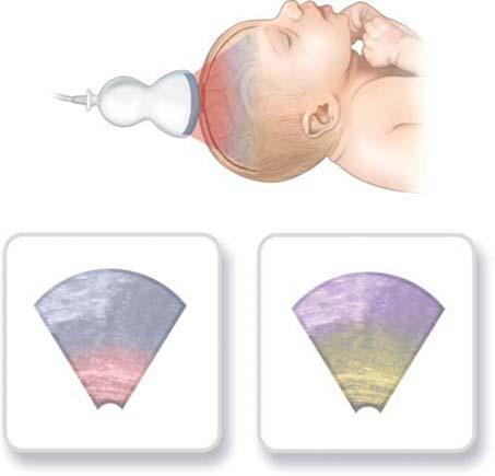
For neonatal brain examinations, the sagittal and coronal planes are most commonly accessed using the anterior fontanelle. For the sagittal plane, the transducer indicator is in the 6 o'clock position and indicates the anterior side of the brain. For the coronal plane, the transducer indicator is in the 9 o'clock position and indicates the right side of the brain (Fig. 1-SG).
IMAGE QUALITY DEFINITIONS
Evaluation of sonographic image quality is learned and communicated using specific definitions. Normal tissue and organ structures have a characteristic echographic appearance relative to surrounding structures. An understanding of the normal appearance provides the baseline against which to recognize variations and abnormalities. These definitions describe and characterize the sonographic image.
An eclw is the recorded acoustic signal. It is the reflection of the pulse of sound emitted by the transducer. Prefixes or suffixes modify the quality of the echo and are used to describe characteristics and patterns on the image.
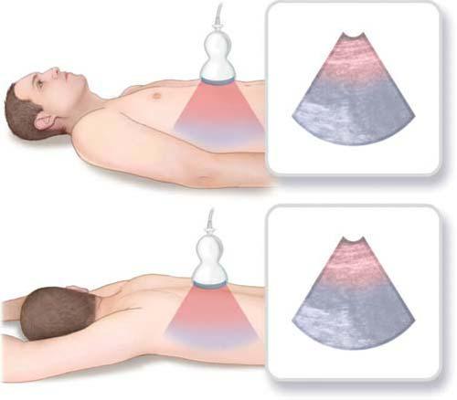
Echogenic describes an organ or tissue that is capable of producing echoes by reflecting the acoustic beam. This term does not describe the quality of the image; it is often used to describe relative tissue texture (e.g., more or less echogenic than another tissue) (Fig. 1-6A,B). An aberration from normal echogenicity patterns may signify a pathologic condition or poor examination technique such as incorrect gain settings.
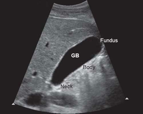
Aneclwic describes the portion of an image that appears echo-free. A urine-filled bladder, a bile-filled gallbladder, and a clear cyst all appear anechoic (Fig . l -6C). Sonolucent is the property of a medium allowing easy passage of sound (i.e., low attenuation). Sonolucent or transonic are misnomers that are often substituted for anechoic. 3 When
the sonographic appearance is anechoic, sonographers frequently use the term cystic. When describing the appearance of the echo, the term anechoic is correct. When describing the histopathologic nature of an anechoic structure, cystic or cyst-like is correct (see "Interpretation of Sonographic CharacteristicsH section).
If the scattering amplitude changes from one tissue to another, it results in brightness changes on an image . These brightness changes require terminology to describe normal and abnormal sonographic appearances. Hyperechoic describes image echoes brighter than surrounding tissues or brighter than normal for a specific tissue or organ. Hyperechoic regions result from an increased amount of sound scatter relative to the surrounding tissue Hypoechoic describes portions of an image that are not as bright as surrounding tissues or less bright than normal. The hypoechoic regions result from reduced sound scatter relative to the surrounding tissue. Eclwpenic describes a structure that is less echogenic than others or has few internal echoes. Isoeclwic describes structures of equal echo density. These terms can be used to compare echo textures (Fig. 1-60).
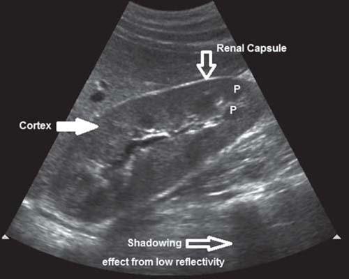
Homogeneous refers to imaged echoes of equal intensity. A homogeneous portion of the image may be anechoic, hypoechoic, hyperechoic, or echopenic. Heterogeneous describes tissue or organ structures that have several different echo characteristics. A normal liver, spleen, or testicle has a homogeneous echo texture, whereas a normal kidney is heterogeneous, with several different echo textures.
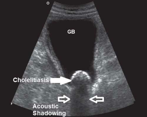
Acoustic enhancement is the increased acoustic signal amplitude that returns from regions lying beyond an object that causes little or no attenuation of the sound beam such as fluid-filled structures. The opposite of acoustic enhancement is acoustic shadowing and both are types of sonographic artifacts. Acoustic shadowing describes reduced echo amplitude from regions lying beyond an attenuating object. An example is seen with echogenic calculi (cholelithiasis, urolithiasis) which does not allow ultrasound to pass through (it is attenuated) resulting in a sharp, distinctive shadow (Fig. l-6E). Air bubbles (bowel gas) do not allow transmission of the sound beam and most of the sound is reflected. 4 Often, sonographers refer to the shadowing caused by low reflectivity as soft or dirty shadowing.
INTERPRETATION OF SONOGRAPHIC CHARACTERISTICS
Three other definitions are frequently used to describe internal echo patterns: cystic, solid, and complex.
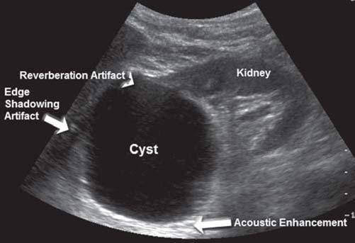
The diagnosis of a cyst is made on many asymptomatic patients based on specific sonographic characteristic appearances and only in certain situations, with a correlation with the patient's history. The sonographic criteria for cystic structures or masses are as follows: (1) Cysts retain an anechoic center, which indicates the lack of internal echoes even at high instrument gain settings. (2) The mass is well defined, with a sharply defined posterior wall indicative of a strong interface between cyst fluid and tissue or parenchyma. (3) There is an increased echo amplitude in the tissue beginning at the far wall and proceeding distally compared to surrounding tissue. This increased amplitude is better known as through-transmission or the acoustic enhancement
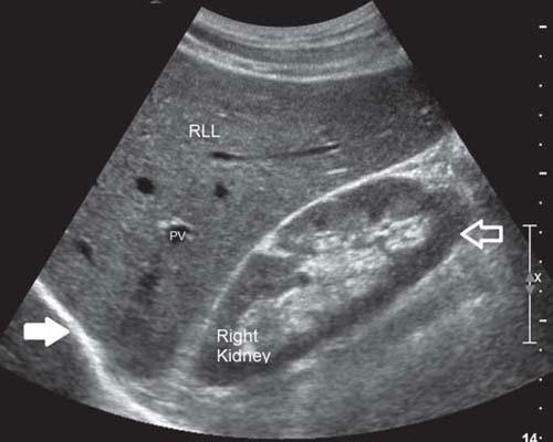
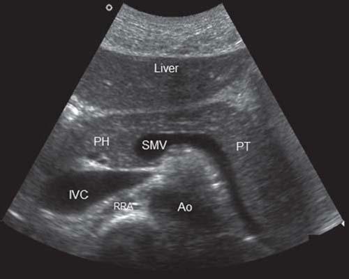
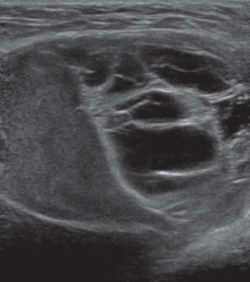
FIGURE 1-6 Tissue texture5. A:. On this longitudinal section in the supine position, 1he diaphl"llglll (v.hite solid <Jm1N) is described as more ediogenic 1han 1he normal texture of1he right liver lobe (RU.), which is more echogenic. 1han 1he renal parendiyma (...Alite am:1N) (FV, portal vein; l'llite solid <XIT1N, diaphragm). B: In 1his patient. the transver.;e section demonstr.rtes 1hat tne liver and panen!aS 11!!X:t!Jres have a similar ediogenicity (ISOl!d'loic) (Ao. aorta; NC, inferiorvena cava; PH, pancrealic head; PT, pancre.alic. tail; RRA, right renal artery; SMV, ruperior mesenteric. vein). C: On 1his longitudinal section made in tne supine position, 1he bile-filled gallbladder (GB) appear$ anecnoic.. 0: On a longitlldinal section of the right kidney, the renal c.ipsule is normally a specular reflector and is hyperechoic compared to surrounding tissues. Tne renal cortex is homogeneously echogenic: and 1he pyramids (P) seel'1 in 1he medulla become more prominent and can diange from hypoechoic. to anechoic with increased diuresis. Tne area labeled shadowing is caused by bowel gas and is due 10 low reflectivity (referred to as soft or dirty shadow). E: The transverse gallbladder is from a patient with diolecy,;ti1is (1hiclcened and a diolelithiasis aealing an acoustic. shadow due to atteN.lation. Compare f\gure I-OE with Figure I-OD with the appearance of a shadow due to low reflec!Mo/. (Images courtesy of Philips Medical System, Bothell, WA)
artifact. It occurs because tissue located on either side of the cystic structure attenuates more sound than does the cystic structure. (4) Reverberation artifacts can be identified at the near wall if the cyst is located close to the transducer. (S} Edge shadowing artifacts may appear, depending on the incident angle {refraction) and the thickness of the cystic wall at the periphery of the structure. The tadpole tail sign occurs with a combination of an edge shadow next to the echo enhancement (Fig. l-7A).
A solid structure may have a hyperechoic, hypoechoic, echopenic, or anechoic homogeneous echo texture, or it may be heterogeneous because it contains many different types of interfaces. Usually, solid structure exhibit the following characteristics: (1) internal echoes that increase with an increase in instrument gain settings; (2) irregular, often poorly defined walls and margins; and (3) low-amplitude
echoes or shadowing posterior to the mass due to increased acoustic attenuation by soft tissue or calculi (Fig. 1-78).
A complex structure usually exhibits both anechoic and echogenic areas on the image, originating from both fluid and soft tissue components within the mass. The relative echogenicity of a soft tissue mass is related to a variety of constiwents, including collagen content, interstitial components, vascularity, and the degree and type of tissue degeneration (Fig. l-7C).
The amplitude of echoes distal to a mass, structure, or organ can be used to evaluate the attenuation properties of that mass. Thlnsonic or sonolucent refers to masses, organs, or tissues that attenuate little of the acoustic beam and result in images with distal high-intensity echoes. An example is a cystic structure with the associated acoustic enhancement artifact. Masses that attenuate large amounts of sound
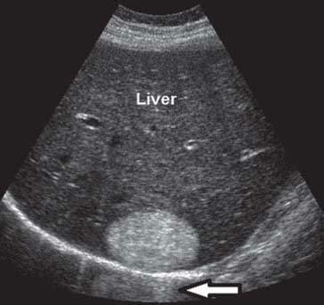
BFIGURE 1-7 lnterpretition. A:. Cystic. A longitlJdinal seaion d the right kidney demonstrates a renal cyst. The following sonographic criteria for a cyst are present (I) anechoic: center; (2) cle.ilr definition witn a sharply defined posterior wall, (3) acoustic enhancement, (4) reverberation artifac:ts art'CN>head), and (S) edge shadowing artifact. 8: Solid. A transverse section 1hrough 1he right lobe of the liver demonstrates a hemanjjoma. The benign solid mass presents wi1h 1he following sonographic aiteria for a solid mass: (I) internal ed:loes that increase witn increased gain settings and (2) lowamplitude echoes (arrow) or shadowing posterior to the mass. may be present when the solid mass is a calculus or a malignant tumor. C: Complex. The encapsulated mass is a complex struc:llJre exhibiting septa. between echogenic and aned10ic areas. (Images courtesy cl Philips Medical System, Bothell, WA)
show a marked decrease in the amplitude of distal echoes. An example is calculi, with the associated shadow artifact.
PREPARATION
Before the patient is scanned, it is important for the sonographer to obtain as much information as possible. The sonographer should be aware of the indications for the study and of any additional clinical information such as laboratory values, results of previous examinations, and related imaging examinations. The sonographic examination should be tailored to answer the clinical questions posed by the overall clinical assessment.
Patient apprehension is reduced when the examination is explained. Apprehension may be lessened further by providing a clean, neat examination room, extending common courtesies and a smile, and letting the patient know that the sonographer enjoys providing this diagnostic service. It is important that patients know that they are the focus of the sonographer's attention.
The region of interest is visualized by planning the sonographic examination to image in multiple planes, two of which are perpendicular. Any abnormalities are imaged with differing degrees of transducer and patient obliquity to collect more information. The patient is released only after sufficient information is documented, because being called back for a repeat examination increases apprehension.
EXAMINATION DOCUMENTATION AND THE SONOGRAPHER'S PRELIMINARY REPORT
The minimum documentation on sonographic images includes (I) the patient's name and other identifying information, (2) the facility's identifying information, (3) date of the examination, and (4) the image orientation if appropriate. 5
In many departments, sonographers provide a preliminary report. Legally, physicians can provide a diagnosis or an interpretive report, whereas sonographers cannot. Sonographers function as a delegated agent of the physician and do not practice independently. 6 The preliminary report is more commonly referred to as the technical impressions or the examination worksheet. The minimum documentation on a technical impression worksheet should include (I) the patient's name and other identifying information, (2) date of the examination, (3) relevant clinical information which may include classification of disease code, (4) specific examination requested, and (S) the name of the patient's health-care provider and contact information. 5 The technical impressions worksheet should give key sonographic findings. Ideally, the sonographer has an opportunity to discuss these findings with the sonologist. As a team, the sonographer and sonologist determine when the documentation is sufficient to complete the sonography examination. When immediate action is indicated by the sonographic findings and the sonologist is unavailable to provide the final interpretive report, the sonographer should provide the referring physician with as much information as possible immediately following the examination.
The sonographer's report should describe the sonographic findings only on what is documented, without
offering a conclusion regarding pathology. The terminology presented previously is very helpful. Include the scanning plane, normal tissue echogenicity, abnormal tissue texture (anechoic, hyperechoic, hypoechoic, isoechoic, cystic, solid or complex, focal or diffused, and shadowing or acoustic enhancement), measurements (vessels, ducts, organs, wall thickness, masses), location of measurements, and abnormal amounts of fluid collections. For example, describing an echogenic mass attached to the gallbladder wall that does not move as the patient changes position discusses the sonographic findings, whereas stating that the patient has a polyp located in the gallbladder is a diagnosis.
The department should have a policy regarding the documentation to include on the image and interpretive report worksheet as well as the final report from the interpreting physician. Sonographers should be competent, through education and experience, to provide images of adequate quality and written documentation of the sonographic findings without legal obligation. 6 Sonographers should not provide any verbal or written sonographic findings to the patient or the patient's family.
While demonstrating their sonographic evaluation expertise, sonographers should always adhere to the codes of medical ethics and/or professional conduct available from professional associations. 6 These codes and clinical practice standards should also be included in the sonographer employment Gob) description.
SENSITIVITY, SPECIFICITY, AND ACCURACY
Sonographers should be aware of a few statistical parameters developed to judge the efficacy of sonographic examinations. These statistics are frequently reported in the literature. Knowing these statistics allows the sonographer to provide a sound rationale for why a diagnostic procedure should or should not be performed.
There are four possible results for each sonographic examination correlated with an independent determination of disease, such as a biopsy or a surgical procedure. (1) A true-positive result means that the sonographic findings were positive and the patient does have the disease or pathology. (2) A true-negative result means that the sonographic findings were negative and the patient does not have the disease or pathology. (3) A false-positive result means that the sonographic findings were positive but the patient does not have the disease or pathology. (4) A false-negative result means that the sonographic findings were negative but the patient does have the disease or pathology. Sonographers should strive to increase both the true-positive and true-negative results.
The examination's sensitivity describes how well the sonographic examination documents whatever disease or pathology is present. Mathematically, it is determined by the equation [true positive + (true positive + false negative) x 100]. If the number of false-negative examinations decreases, the sensitivity of the examination increases.
The examination's specificity describes how well the sonographic examination documents normal findings or excludes patients without disease or pathology. Mathematically, it is determined by the equation [true negative + (true negative + false positive) x 100]. If the number of false-positive
examinations decreases, the specificity of the examination increases.
The accuracy of the sonographic examination is its ability to find disease or pathology if present and to not find disease or pathology if not present. Mathematically, it is determined by the equation [true positive + true negative+ (all patients receiving the sonographic examination) x 100]. There are two other statistics that sonographers should be aware of. The positive predictive value indicates the likelihood of disease or pathology if the test is positive. Mathematically, it is detennined by the equation
SUMMARY
• Learning and understanding accurate and precise terminology allows commUIJication among professionals.
• Developing standard protocols based on understanding patient positions, transducer orientations, and image presentations increases the accuracy of the sonography examinations.
• Sonographers describe sonographic findings with terminology that defines echo amplitude, echo texture, structural borders, characteristics of organs and anatomic relationships, sound transmission, and acoustic artifacts and identifies cystic, solid, and complex masses.
• The sonography examination relies on the skill, knowledge. and accuracy of the sonographer who must pay attention to the texture, outline, size. and shape of both normal and abnormal structures.
• The patient will benefit most when the sonographic appearance is correlated with patient history, clinical presentation. laboratory function tests, and other imaging modalities to compose a clinically helpful picture.
[true positives+ (true positives+ false positives) x 100]. The negative predictive value indicates the likelihood of the patient being free of disease or pathology if the test is negative. Mathematically. it is determined by the equation [true negatives + (true negatives + false negatives) x 100].
The mathematical formulas presented provide a percentage. If sensitivity, specificity, accuracy, and positive and negative predictive values are expressed by fractions between 0 and 1 rather than by a percentage, the parameters were not multiplied by 100.
CRITICAL THINKING QUESTIONS
1. If the patient is lying on his or her right side and the transducer indicator is at the 12 o'clock position on the left Jateral abdominal wall, what is the scanning plane and how is the image presented on the display monitor1
2. What anatomic areas are not visualized on a longitudinal, sagittal image presentation and how does the sonographer evaluate these areas?
3. Explain the mechanism and differentiate between acoustic shadowing and low refiectivity due to air bubbles.
MEDIA MENU
Student Resources available on thePoint• include:
• Audio glossary
• Interactive question bank
• Internet resources
REFERENCES
1. American Institute of Ultrasound in Medicine. AlUM Tuchnical Stan.d/l1'ds Comm.itttt: Stmu1.a:rd Presentation and Labeling of Ultmsound Images. Stb ed. Laurel, MD: American lns!itute of Ultraaound in Medicine; 2013.
2. Tempkin BB. Scanning planes and scanning methods. In: Tumpkin BB, ed. Sonography Scanning: Principles and 1'1:otDaJU. 4th ed. St. Louis, MO: msmer; 2013:15-28.
3. American lnalitute of Ultrasound in Medicine .AruM Recommended Ultmsound 'n!rminology. 3rd ed. Laurel, MD: American Institute af Ultrasound in Medicine; 2008.
S. American Institute of Ultrasound in Medicine. AlUM Practice Pammeter for Docu.numtaJ:iDn of an Ultnzsound Emmination. Laurel, MD: .American Institute of Ultrasound in Medicine; 2014.
6. Society of Diagnostic Medical Sonography. Scope of Practice and Clinical Standards for the Diagnostic Mediml Sonographer. Plano, TX: Society of Diagnostic Medical Sonography; 2013-2015.
ABDOMINAL SONOGRAPHY
The Abdominal Wall and Diaphragm
TERRIL. JURKIEWICZ
OBJECTIVES
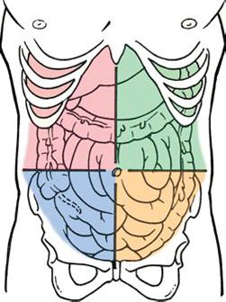
Locate the nine regions of the abdomen and the four quadrants of the abdominopelvic cav ity.
Discuss the extent, the muscles , and the subcutaneous layers of the abdominal wall a'.E diaphragm.
Describe the role of sonography, the sonographic technique, and the normal onographic appearance of the abdominal wall and diaphragm.
Identify the etiology and sonographic appearance of acute and t,;,to ~ic al5~ inal wall infiammatory process to include resolution, organization, and absces's::fom;i ation.
Describe the common etiologies and sonographic appearanQ-ab ei ominal wall hematomas and trauma.
Identify the different types of abdominal hernias and hi eir s01\1 ographic appearance. List the neoplasms that affect the abdominal ~I an <:l tlesc[i oe their sonographic appearance. Identify diaphragmatic pathologies that can be e~a~ d with sonography.
Identify technically satisfactory and unsatisfacto sonographic examinations of the abdominal wall and diaphragm.
GLOSSARY
abscess a cavity containing dead tissue and pus that forms due to an infectious process ascites an accumulation of serous fiuid in the peritoneal cavity ecchymosis skin discoloration caused by the leakage of blood into the subcutaneous tissues, which is often referred to as a bruise erythema redness of the skin due to infiammation linea alba fibrous structure that runs down the mid line of the abdomen from the xiphoid process to the symphysis pubis separating the right and left rectus abdominis muscles omphalocele a congenital defect in the midline abdominal wall that allows abdominal organs, such as the bowel and liver, to protrude through the wall into the base of the umbilical cord peristalsis rhythmic wavelike contraction of the gastrointestinal tract that forces food through it pneumothorax collapsed lung that occurs when air leaks into the space between the chest wall and lung
The human body contains two major cavities: the ventral (anterior) cavity and the dorsal (posterior) cavity. The dorsal cavity is divided into the cranial cavity and the spinal cavity. In the ventral cavity, the diaphragm muscle separates the thoracic cavity from the abdominopelvic cavity. The abdominopelvic cavity has an upper portion (the abdomen). a lower portion (the pelvis). and it is surrounded by the abdominal wall This chapter focuses on the abdominal wall and diaphragm.
REGIONS AND QUADRANTS
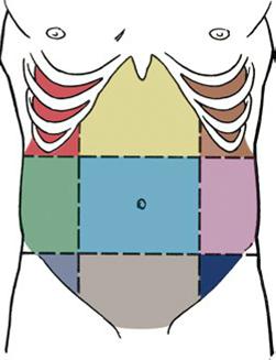
For clinical reasons used to descnoe the location of organs, pain, or pathology, the abdomen is divided into nine region& and the abdominopelvic cavity is divided into four quadrants. The nine regions are delineated by two horizontal (transverse) planes and two vertical (longitudinal) planes and the four quadrants are delineated by one horizontal (transverse) plane and one vertical {longitudinal, midsagittal, or sagittal} plane. 1.2 The nine regions are the (1) right hypochondrium. (2) epigastrium, (3) left hypochondrlum, (4) right lumbar. (5) umbilical, (6) left lumbar, (7) right iliac fossa, (8) hypogastrium, and (9) left iliac fossa. 1.2 The four quadrants are the (1) right upper quadrant (RUQ}, (2) left upper quadrant (LUQ). (3) right lower quadrant {RLQ), (4) and left lower quadrant (LLQ)M (Fig. 2-lA,B).
ANATOMY
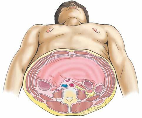
The abdominal wall is continuous but, for descriptive reasons, it is divided into the anterior wall, right and left
lateral walls, and posterior wall. Because the anterior and lateral wall boundaries are indefinite, they will be combined in the presentation as they are combined in other references1.2 (Fig. 2·2).
Anterolateral Abdominal Wall
The anterolateral wall extends from the thoracic cage to the pelvis. Superiorly, it is bounded by the cartilages of the 7th to 10th ribs and the xiphoid process. Inferiorly, it is bounded by the inguinal ligament and iliac crests, pubic crests, and pubic symphysis of the pelvic bones.4
Layers
To better understand abdominal wall anatomy, it is important to distinguish between fascia and aponeurosis. A fasci.a. is a fibrous tissue network located between the skin and the underlying structures. It is richly supplied with both blood vessels and nerves. The fascia is composed of two layers: a superficial layer and a deep layer. The superficial fascia is attached to the skin and is composed of connective tissue containing varying quantities of fat. The deep fascia underlies the superficial layers to which it is loosely joined by fibrous strands. It serves to cover the muscles and to partition them into groups. Although the deep fascia is thin, it is more densely packed and is stronger than the superficial fascia; however, neither the superficial fascia nor the deep fascia possesses any notable internal strength since they are a condensation of connective tissue organized into definable homogeneous layers within the body. s
FIGURE 2-1 AbdominopeMc cavity subdivisions. k The regions are formed by two sagittal ('lelt.icaf) and two tranMrse {horiz.onrt.11) planes. B: The quadrams are funned by the midsagittal plane and atranMlrse plane passing through the umbiliws at the iliac creit or the disk level between the 13--4 vertebrae. (Reprinted with pennissionfrom Moore Essential C/inica/Anaumy. 3rd ed. MD: Lippincott Wiiiams& Willcins: 2007:119.)
Median plane
B Four abdominal quadranta
Inferior vi..,,,
FIGURE 2-2 Abdominal wall subdivisions. The 1ransverse section illuWates the structural relationships of the abdominal wall. (Reprinted with permission from Moore K. Dalley A >€ur A OinicaJ/y Orientlld Anattxrtf. 6th ed. Philadelphia, PA: Lippinaitt Williams & Wilkins; 20 I0: 186.)
The aponeurose.s are layers of fl.at tendinous fibrous sheets fused with strong connective tissue that serve as tendons to attach muscles to fixed points. An aponeurosis is minimally served by blood vessels and nerves. The aponeuroses are primarily located in the ventral abdominal regions with a primary function to join muscles to the body parts that the muscles act upon. An aponeurosis possesses excellent strength.3
The multilayered abdominal wall appean as a laminated structure when viewed from the superficial, outermost layer to the deep layer.4 It consists of skin, subcutaneous tissue (superficial fascia), muscles and their aponemoses, a deep fascia, extraperitoneal fat, and the parietal peritoneum. l,M The skin attaches loosely to most of the subcutaneous tissue except that it normally adheres firmly at the umbilicus. u
The subcutaneous tissue anterior to the muscle layers makes up the superficial fascia. Superior to the umbilicus,
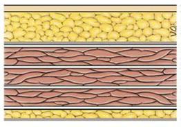
it is consistent with that found in most regions. Inferior to the umbilicus, the deepest part of the subcutaneous tissue is reinforced with elastic and collagen fibers and is divided into two layers. The first is a superficial fatty layer (Camper fascia) containing small vessels and nerves. camper fascia gives the body wall its rounded appearance. The second layer is a deep membranous layer {Scarpa fascia) and it consists of a combination of fat and fibrous tissue that blends with the deep fascia. 1.2 The membranous layer continues into the perineal region as the superficial perinea! fascia (Coll.es fascia) 1 {Fig. 2-3).
The three anterolateral abdominal muscle layers and their aponeuroses (flat extended tendons) are covered by the superficial, intennediate, and deep layers of extremely thin investing fascia. 1 The investing layer of fascia is located on the external aspects of the three muscle layers and is not easily separated from the external muscle layer. Varying thicknesses of membranous and areolar sheets of endoabdominal fascia line the internal aspects of the wall. Although the endoabdominal fascia is continuous, different names account for the muscle or aponeurosis it is lining. For ex.ample, the portion liniDg the deep surface of the transversus abdominis muscle and its aponeurosis is the transversalis fascia. Internal to the transversalis fascia is the parietal peritoneum. The distance separating the parietal peritoneum from the transversalis fascia is determined by the variable amounts of extraperitoneal fat in the fascia. 1 The parietal peritoneum is a glistening lining of the abdominopelvic cavity formed by a single layer of epithelial cells and supporting connective tissue1•2 (see Fig. 2·3).
Muscles
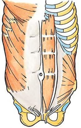
There are five bilaterally paired muscles in the anterolateral abdominal wall and one unpaired. muscle (Tu.ble 2-1). Located bilaterally on the anterior abdominal wall are the rectus abdorninis muscles (see Fig. 2-2). The rectus abdominis is a long, broad, vertical, strap-like muscle that is mostly enclosed in the rectus sheath. Also located on the anterior abdominal wall in the rectus sheath is the pyramidal.is muscle. The pyramidali.s, a small triangular muscle, is considered insignificant and is absent in approximately 20% of people1 • 2 {Fig. 2-4A).
There are three flat, bilaterally paired muscles of the anterolateral group: (I} the external oblique (most superficial), (2} the internal oblique (middle layer), and (3) the transversus abdominis (also known as transverse
Superficial tatty layer of Skin subcutaneoustlBSue(Camperfascla) --;-
Deep membranous layer of
oblique muse!& subcutaneous ti$11ue (Scarpa al bl. 1 • • ""!"" s ern o 1quemusce lnv&Sting (deep) fascia: :;;
;;z ..,,,lhlnswrse abdominal muscle superficial, intermediate, deep :::<'. Extraperttoneal fat
Endoabdominal
' ' 7"' Parietal peritoneum fascia
FIGURE 2-3 Anterolateral abdominal wall. The section of1he anterolateral abdominal wall inferior to 1he umbilicus illustrates the multilayered, tissue and musdes located anterior to 1he peritoneal cavity.
Deep
Linea alba
Lumbar vertebra
TABLE 2-1 Muscles of the Abdominolateral Wall 1.2
Rectus abdominis
(Rgs. 2-2 and 2-4A)
Pyramidal is (Rg. 2-4A)
Bilaterally paired, vertical muscle
Origin: Arises from the front of the pubic bone and pubic symphysis
Insertion: Inserts into the frfth, sixth, and seventh costal cartilages and the xi phoid process Action: Acts to flex the trunk, compress abdominal viscera, and stabilize and control pelvic tilt
Small, insignificant triangular musde
Origin: Arises from the anterior surface of the pubis
Insertion: Inserts into the linea alba; lies anterior to the lower part of the rectus abdomi nis Action: Acts to draw the linea alba inferiorly
External oblique Bilaterally paired, flat muscle
(Rgs. 2-2 and 2-4B,q
Origin: Arises from the external surface ofthe lower eight ribs
Insertion: Inserts in linea alba via an aponeurosis and into the iliac crest and pubis via th e inguinal ligament Action: Acts to compress and support abdominal viscera, flexes and rotate t runk
Internal oblique Bilaterally paired, flat muscle
(Rgs. 2-2 and 2-4B,q
Transversus abdominis (transverse albdominal; Figs. 2-2 and 2-4B,q
Origin: Arises from the thoracolumbar fascia and the anterior two-thirds of the iliac crest
Insertion: Inserts into the inferior borders of 'ttle lower three ribs, linea alba, and pu bis via a conjo int tendon
Action: Acts as a postural function of all albdominal muscles
Bilaterally paired, fla:t muscle
Origin: Arises from the internal surfaces of the lower eight cost.al cartilages , 712 th e thoracol umbar fasc ia, th e anterio r two-thirds of the iliac crest, and the lateral 'ttlird of the inguinal ligame nt
Insertion: Inserts into the xiphoid process, linea alba with aponeurosis of inte rnal oblique , pubic crest , and pectin pubis via a conjoint tendon
Action: Same as external oblique; acts to compress and support albdomi nal viscera
abdominal) 13 (see Fig. 2-2 and Table 2-1). Coupled with the vertical orientation of the fibers of the rectus abdominis, the fibers in the three flat muscles are arranged to provide maximum strength by forming a supportive muscle gird.le that covers and supports the abdominopelvic cavity. In the external oblique, the muscle fibers have a diagonal inferior and medial orientation. The fibers of the internal oblique, the middle muscle layer, have a perpendicular orientation at right angles to those of the external oblique The fibers of the innermost muscle layer, the transversus abdominis, are oriented transversely or horizontally. 13
Structures
The other structures within the anterolateral abdominal wall include the rectus sheath, linea alba, umbilical ring, and the inguinal canal.
The rectus sheath is the strong, fibrous compartment for the rectus abdominis and pyramidalis muscles as well as for some arteries, veins, lymphatic vessels, and nerves The anterior and posterior layers of the rectus sheath compartment are formed by the intercrossing and interweaving of the aponeuroses of the flat abdominal muscles. The lateral aspect of the rectus abdominis, the aponeuroses, fuses to form the linea semilunaris.3 The arcuate line is located half way from the umbilicus to the pubis symphysis and refers to the transition terminating the posterior rectus sheath covering the proximal, superior three-quarters of the rectus abdominis muscle.3 The distal, inferior quarter is covered by the transversalis fascia, which lies below the rectus muscles and is all that separates the rectus muscles from the peritoneum3 (Fig. 2-SA,B).
Throughout its length, the linea alba is formed as fibers of the anterior and posterior layers of the sheath interlace in the anterior median line. 13 The linea alba is oriented
vertically and courses the length of the anterior abdominal wall. It separates the bilateral rectus sheaths. Superiorly, the Iinea alba is wider and it narrows inferior to the umbilicus to the width of the pubic symphysis. The linea alba transmits small vessels and nerves to the skin (Figs. 2-2, 2-4A, and 2-SA,B). In thin, muscular people, a groove is visible in the skin overlying the linea alba.
The umbilicus is the area where all layers of the anterolateral abdominal wall fuse 1 The umbilical ring is a defect in the linea alba and is located underlying the umbilicus. 1 • 2 This is the area through which the fetal umbilical vessels passed to and from the umbilical cord and placenta After birth, fat accumulation in the subcutaneous tissue raises the umbilical ring and depresses the umbilicus.
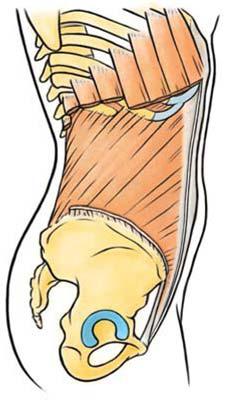
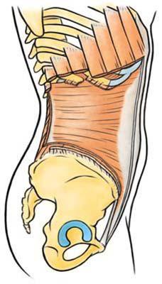
The inferior border of the external oblique extends between the anterior superior iliac spine and the pubic tubercle forming the inguinal ligament.3 Located in the inguinal region superior and medial to the inguinal ligament is the inguinal canal, which is formed during fetal development. It is an important canal where structures exit and enter the abdominal cavity, and the exit and entry pathways are potential sites of herniation 13 In adults, the inguinal canal is an oblique passage approximately 4 cm long It has an inferior-to-medial orientation through the inferior part of the anterolateral abdominal wall and lies parallel and superior to the median half of the inguinal ligament.2 Functionally and developmentally distinct structures located within the canal are the spermatic cord in males and the round uterine ligament in females Other structures included in the canal in both sexes are blood and lymphatic vessels and the ilioinguinal nerves. The inguinal canal has two openings. The deep (internal) inguinal ring serves as an entrance and the superficial (external) inguinal ring serves as the exit for the spermatic cord or the round ligament in females . Normally, the inguinal canal is collapsed anteroposteriorly against the
A Antwtor view
Internal B
Lateralvltwa
External oblique (cut)
Rectus sheath (anterior layer)
Internal oblique--.'Hf (cut)
Extemal obllque (cut)
ligament
FIGURE 2-4 Abdominolateral wall muscles. A; The bilaterally vertially oriented redl.Js abdcminis muscles and the small triangular pyramidalis muscle are located on 1he anterior wall. The 1hree flat, bilaterally paired muscles comprising the anterolateral group include the external oblique, 1he intemal oblique, and 1he transverse abdcminal. The strength of1he muscles can be contributed to 1he collaborative relationship of1he orientation of1he fiber d eacn muscle. (Reprinted with permission from Moore KL, AM. Essential Oinkal /\nat.txrrt. 3rd ed. Baltimore, MD: Lippincott Williams & Wikins; 2007: 122.)
sperm.atic cord or round ligament. Between the two openings (rings), the inguinal canal has two walls (anterior and posterior), a roof, and a fl.oor1·2 (Table 2-2; Fig. 2-6A,B).
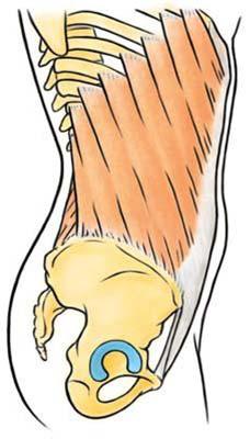
Posterior Abdominal Wall
The posterior abdominal wall is composed of the lumbar vertebra, posterior abdominal wall muscles, diaphragm, fascia, lumbar plexus, fat, nerves, blood vessels, and lymphatic vessels.
Layers
The posterior abdominal wall is covered with a continuous layer of endoabdominal fascia, which is continuous
with the transversalis fascia. 1.2 The posterior wall fascia is located between the parietal peritoneum and the muscles. The psoas fascia (sheath) is attached medially to the lumbar vertebrae and pelvic brim. Superiorly, the psoas fascia is thickened and forms the medial arcuate ligament. Laterally, the psoas fascia fuses with both the quadratus lumborum fascia and the thoracolumbar fascia. Inferior to the iliac crest, the psoas fascia is continuous with that part of the iliac fascia that covers the iliacus1 (Fig. 2-7).
On the posterior abdominal wall, the thoracolumbar fascia is an extensive complex. Medially, it attaches to the vertebral column. In the lumbar region, the thoracolumbar fascia has posterior, middle, and anterior layers with enclosed muscles between them. The fascia is thin and transparent in