HANDBOOK OF MULTIPHASE FLOW ASSURANCE
Taras Y. Makogon
Gulf Professional Publishing is an imprint of Elsevier
50 Hampshire Street, 5th Floor, Cambridge, MA 02139, United States
The Boulevard, Langford Lane, Kidlington, Oxford, OX5 1GB, United Kingdom
© 2019 Elsevier Inc. All rights reserved.
No part of this publication may be reproduced or transmitted in any form or by any means, electronic or mechanical, including photocopying, recording, or any information storage and retrieval system, without permission in writing from the publisher. Details on how to seek permission, further information about the Publisher’s permissions policies and our arrangements with organizations such as the Copyright Clearance Center and the Copyright Licensing Agency, can be found at our website: www.elsevier.com/permissions.
This book and the individual contributions contained in it are protected under copyright by the Publisher (other than as may be noted herein).
Notices
Knowledge and best practice in this field are constantly changing. As new research and experience broaden our understanding, changes in research methods, professional practices, or medical treatment may become necessary.
Practitioners and researchers must always rely on their own experience and knowledge in evaluating and using any information, methods, compounds, or experiments described herein. In using such information or methods they should be mindful of their own safety and the safety of others, including parties for whom they have a professional responsibility.
To the fullest extent of the law, neither the Publisher nor the authors, contributors, or editors, assume any liability for any injury and/or damage to persons or property as a matter of products liability, negligence or otherwise, or from any use or operation of any methods, products, instructions, or ideas contained in the material herein.
Library of Congress Cataloging-in-Publication Data
A catalog record for this book is available from the Library of Congress
British Library Cataloguing-in-Publication Data
A catalogue record for this book is available from the British Library
ISBN: 978-0-12-813062-9
For information on all Gulf Professional publications visit our website at https://www.elsevier.com/books-and-journals
Publisher: Brian Romer
Senior Acquisition Editor: Katie Hammon
Editorial Project Manager: Joshua Mearns
Production Project Manager: Anitha Sivaraj
Cover Designer: Christian J. Bilbow
Typeset by SPi Global, India
Dedication
To my teachers Prof. Yuri F. Makogon, Yakov F. Lerner, Prof. E. Dendy Sloan, and Prof. M. Sami Selim.
Preface
This handbook is a compilation of reference materials and experiences related to flow assurance collected over the years. This handbook may help the production operator identify and solve issues faster and also help a project development engineer design the most critical flow assurance issues out of the system more cost-effectively. The intent of
this book is to deliver safe, reliable and economic design and operation of multiphase production systems with flow assurance threats. Flow assurance is used in onshore, offshore and subsurface flow of petroleum fluids. This diversity of application of flow assurance control methods motivated the development of this handbook.
Flow assurance aims to make sure oil and gas keep flowing. To achieve that goal, flow assurance relies on the analysis of multiphase flow and on the selection and use of production chemicals. Flow assurance engineers commonly analyze the flow of oil and gas in wells, production flowlines, process facilities and export pipelines. Complex networks of gathering lines feeding into trunk flowlines exist in onshore and offshore fields, and the analysis to optimize flow routing through such networks is equally complex.
Definitions of flow assurance are numerous, including this one: Flow Assurance is the analysis of thermal, hydraulic and fluid-related threats to flow and product quality and their mitigation using equipment, chemicals and procedure.
Multiphase production problems: Blockages and restrictions
Oil and gas are currently produced through wells and pipelines. The lack of flow in wells and pipelines may be due to low reservoir pressure or productivity, due to complete blockages or due to partial restrictions.
Flow restrictions may happen in a reservoir, in a well production tubing or a tree, in a jumper between a well and a flowline, in a flowline, in a riser or in an export pipeline. In some cases, restrictions may happen in several locations simultaneously. The largest number I have seen is five blockages in the same production flowline at the same time. Restrictions may also occur in water and gas injection systems as in wells, flowlines or reservoirs.
Restrictions may be hydraulic, such as liquid accumulation also known as a holdup in flowlines and risers, liquid loading in wells, or mechanical such as a partly closed valve or a scraper. Restrictions or blockages may also be solid, including organic (e.g., paraffin wax), inorganic (scale) or particulate (sand). The hydraulic, mechanical or solid restrictions may be stationary such as the liquid holdup or moving such as the slugging. A flow assurance practitioner should be able to recognize the signs of and potential for any type of restriction and either economically design it out of a new system or mitigate it in an existing system.
In some cases, restrictions may lead to other restrictions. There is an early 2000s example from West Africa offshore production where a wax deposit in a flowline got scraped by a formed hydrate plug into a solid paraffin wax blockage. Similarly, combined hydrate-paraffin restrictions have also formed in the North Sea in the early 1990s and asphaltene-hydrate in the Gulf of Mexico in the 2010s. Paraffin-asphaltene-sand restrictions have been common in Siberian pipelines through the decades.
Modeling of multiphase flow can be done to find optimal conditions for a stable production of gas and hydrocarbon liquids with water. When the gas flow rate is not high enough to sweep the liquid hydrocarbons and liquid water from a well or a pipeline, these liquids accumulate in low spots because of gravity.
The liquids can accumulate either downhole in a vertical well or at a heel or a toe, whichever is lower, in a horizontal well which is known as liquid loading. Both deepwater and shale horizontal wells are susceptible to liquid loading.
Severe slugging is one of the issues in multiphase flow also related to gravity. Liquids can accumulate at a subsea riser base and then get periodically produced to a topsides separator after a sufficient gas pressure has built up behind the accumulated liquids as a large sudden gush of liquid preceded by a period of no or limited flow, which is known as severe slugging. Wells keep producing during severe slugging at a steady rate, but backpressure on wells may change noticeably between slug accumulation and displacement. Severe slugs keep repeating, and slug size and momentum are substantial as to cause vibration at pipe bends in flow geometry, overfill the process vessel or both.
Liquids also can accumulate in the low spots of a near-horizontal pipeline and get periodically displaced by a steady flow of gas, which leads to terrain slugging. Terrain slugs keep repeating and are usually smaller in size and don't overfill the process vessel but may cause
vibration at pipe bends. Hydrodynamic slugging occurs as liquids holdup is displaced by an increasing flow of gas from a flowline in form of a liquid surge. If the surge volume is significant, the hydrodynamic slugs can be as detrimental as severe slugs. Hydrodynamic slugs occur once per a change in production rate and don't repeat.
In all three cases of liquid loading, severe slugging and terrain slugging gravity plays the key role in overcoming the energy emerging from the expanding gas or a single phase or supercritical fluid (also known as the dense phase) or an aquifer which is less than sufficient to lift the liquids to the separator or a slugcatcher.
Analysis of multiphase fluid flow is in part based on information from reservoir modeling prediction of flow rates and on thermodynamic PVT characterization of produced fluids. Software which tracks and balances masses and velocities of produced fluids is available to help predict and analyze the flow velocities and the quantities of accumulation (also known as holdups) of liquid and other phases in the production system. An accurate prediction allows the design engineer to select proper sizes for the well production tubing and for gathering flow lines, and also to identify which technologies would be necessary and most economically suited to produce gas and oil from a reservoir.
Savings from using flow assurance
Flow, which may be single phase (natural gas, oil, water, CO2) or multiphase (two or more single phases) is the key metric of the main product of petroleum companies. Those companies which have more barrels of flowing product per employee generally do well, and vice versa.
Flow assurance is becoming a critical path discipline when other disciplines such as pipeline engineering, subsea layout, artificial lift equipment, and, in some projects, reservoir engineering, wait for flow assurance to compare and validate the viability of an overall architecture for a concept of field development before proceeding with the design. The accuracy in flow assurance makes a project more, less or not at all profitable. This handbook helps organize and streamline the work in flow assurance, in order to make it more accurate.
The use of flow assurance technology saved billions of dollars for oil companies. There are several examples of how multiphase flow tools have resulted in savings for Statoil, Shell, BP, ENI:
• Multiphase technology & OLGA—Norske Shell—Troll—30 Billion NOK
The flow assurance savings for the Norske Shell—Troll field from multiphase technology and the use of an early version of the OLGA software were 30B NOK which is billions of dollars.
“Direct electric heating has saved us billions of kroner on the Norwegian shelf,” said Atle Harald Børnes, who is a specialist at Statoil's Technology and New Energy Business Area.
This system has been installed during the laying of pipelines linked to the Åsgard, Huldra, Kristin, Urd, Tyrihans, Alve and Morvin fields. A version of this heating system has also been prepared as a contingency measure for installation on the pipeline leading from the Ormen Lange field to Aukra.
The heating system was also installed at the BP-operated Skarv field, which has been put on stream after 2011.
The Italian company ENI has also opted to utilize the same system for its Goliat field development offshore Finnmark (Nilsson et al., 2010).
• Hydrates and electrical heating—Statoil, BP—N.Sea—Billions of NOK
Introduction
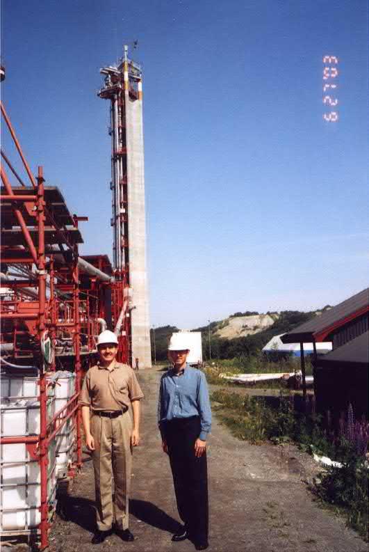
Construction initiative of the multiphase flow loop at Tiller near Trondheim, Norway was pioneered by Esso Norge looking to evaluate the stability of multiphase oil and gas production from offshore reservoirs, and supported by this and other companies. The cost to construct this flow loop was over 26 million in 1980 US dollars. The choice of location was economically justified because the Norwegian sector of the North Sea showed promising acreage and because the Norwegian law allowed some research cost to be deducted from taxable revenue. Numerous sets of data were collected from this test facility which, to this day, are used to validate multiphase software (Caspersen et al., 2011).
The Tiller multiphase flow loop shown in Fig. 1.1 is perhaps the one most important facility used for development of data sets for validation of several multiphase flow models.
Fig. 1.1 Tiller flow loop and tower for multiphase flow research.
Flow assurance technology development also has its roots in PROCAP 1000, a technology program executed by Petrobras from 1986 to 1991, comprised 109 multidisciplinary projects. The cost of the program was 68 million USD. The projects developed under PROCAP 1000 gave rise to a significant part of the 251 patents obtained by Petrobras between 1987 and 1992. It also allowed access to subsea oil fields in water deeper than 300 m which could not be accessed through diving, and the development of deepwater assets to a water depth of 1000 m, which led to capital investment in fields such as Marlim and Albacora and multi-billion profits from Petrobras' deepwater projects (Morais, 2013).
Examples of flow assurance problems
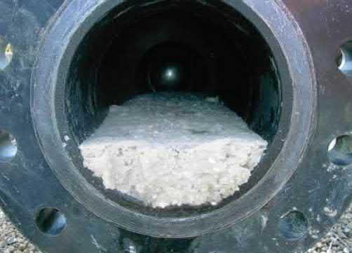
Solids such as hydrates shown in Fig. 1.2–1.4, wax or scale can form blockages and restrict production. These solids can also affect mechanical integrity of a production system in multiple ways, such as erosion, rupture or collapse of pipelines. For example, hydrates can move as projectiles. In a few instances offshore, a partly dissociated hydrate plug got launched from a platform scraper receiver by gas pressurized behind the hydrate.
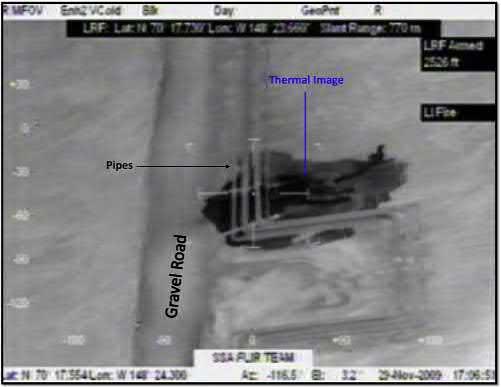
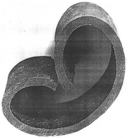
Ice blockages also can present a problem. In an onshore operation in Alaska, an ice blockage formed in the smaller of the two flowlines operating in parallel due to differences in flow distribution. Freezing caused a 24-in. long rupture as shown in Fig. 1.5 at the bottom of a three-phase common line carrying a mixture of crude oil, produced water, and natural gas. Corrosion caused a similar event in 2007 with imagery available at Alaska (2008). A 6-in. long crack (about 1/8 in. wide at the center) formed in the flow line due to external corrosion. Hydrates can also crush or collapse steel tubing such as a well production tubing as shown in Fig. 1.6 in locations where water and gas accumulate at hydrate conditions in the same way ice can crack an engine block if water is used as a coolant instead of an antifreeze.
A paraffin wax deposit can form when heavy hydrocarbon molecules with straight chains of carbon atoms, also known as normal paraffins, precipitate on cold surfaces and
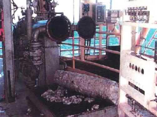
Fig. 1.2 Hydrate slush in a flowline after hydrate blockage was dissociated by depressurization in an onshore Teapot Dome oil field.
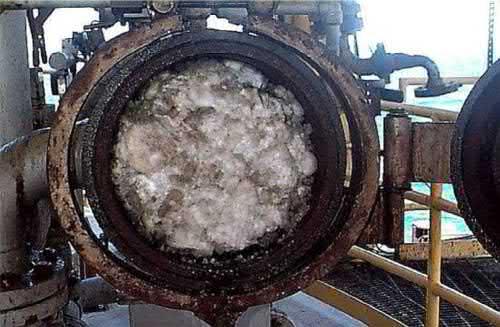
Fig. 1.3 Hydrate slush accumulated and compacted in service platform scraper receiver during flowline depressurization offshore Brazil, ca 1992.
Fig. 1.4 Hydrate extracted from service platform scraper receiver after subsea line depressurization. The compacted hydrate remained solid and did not break upon falling from the scraper receiver.
accumulate, which restricts normal production. In some cases, condensates produced with free gas from deposits may contain heavier hydrocarbon molecules so wax can deposit from condensate during gas production as well as during oil production. In subsea practice, one solid may lead to another.
In the analysis of wax deposition, one should distinguish such fluid characteristics as wax appearance temperature (WAT) when the first visible or detectable solid wax crystal precipitate, and wax dissolution temperature (WDT) when the precipitated wax crystals completely redissolve in the volume of oil from which they crystallized. There is also another term which is important for wax management design: the “wax deposit melting
Fig. 1.5 Thermal image of Alaska hydrocarbon loss of containment caused by ice blockage (Alaska, 2010).
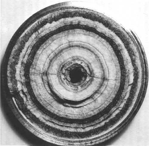
Fig. 1.6 Well tubing collapsed by hydrate formation in a shut-in well annulus between tubing and casing. Onshore Siberia, 1965. T = 8°C, P collapse >800 atm, Tubing wall thickness 6 mm, inside diameter 63 mm. Photo by Yuri F. Makogon.
temperature” (WDMT). The WDMT occurs at a temperature when a wax deposit accumulated over time in a field flowline melts without added oil or solvent. WDT is typically 10–20 °C higher than WAT, whereas WDMT can be 30–40 °C higher than WAT, depending on how long the wax had to age in the field flowline and how much of the heavy fractions it had concentrated.
Crystals of normal paraffin wax, as well as many other crystals, can rotate the plane of light linear polarization and shine. This phenomenon is used in cross-polarized microscopy (CPM) to determine WAT. Networks of waxy crystals called gels, which also shine in a cross-polarized microscope, are therefore composed of wax crystals, not of amorphous non-crystalline material. The term gel is used in relation to wax to signify that the whole bulk of oil converts to a non-flowing material when its temperature drops below pour point and a waxy gel is formed. However, the waxy gel material is not uniform and contains both solid wax and liquid oil trapped between solids. One should recognize when discussing incipient, or initial, wax deposition on a pipe wall that it is wax crystals made up of concentrated normal paraffins or isomerized saturated alkanes that deposit, not a gel which has the same composition as base oil.
A combined hydrate and wax blockage formed in the North Sea in the past in the Staffa field led to costly remediation by depressurization to melt the hydrate. After the first blockage got removed, the second blockage formed, which led to an abandonment of the subsea flowline.
In another case offshore West Africa, an incompletely dissociated hydrate plug started to move in a pipeline and acted as a scraper, compacting the existing paraffin wax deposit into a solid blockage, which could no longer be melted simply by depressurization, and led to a lengthy process of solvent injection past the low-permeability paraffin plug which eventually got removed.
Scale can form as shown in Figs. 1.7 and 1.8 when reservoir water, which may exist near the oil or gas deposit, has some minerals dissolved in it. At reservoir conditions, the formation water is usually partly saturated with salt, or in some cases may be near the equilibrium
Fig. 1.7 Scale buildup inside a heat exchanger tube (Lebedev, 2010).
saturation. As water flows from the reservoir with the produced gas or oil, its pressure and temperature change, which affects the solubility of dissolved ions in water. Saturation limit for some ions may also be reached because water composition changes if the water table rises to the produced zone from another zone. Similarly, waters saturated with different ions from different zones mix, some ions combine and solid scale may form and restrict the pores in reservoir rock or in well tubing, thus limiting the productivity.
Saturation limit for salt ions in water may also be reached because water molecules get consumed to form a hydrate leading to a concentrated brine, or because of the change of pressure or temperature.
Hydrate formation can also lead to precipitation of solid salt scale in small-volume closed systems (Hu et al. 2017a,b, 2018)
Petroleum industry access to ultra deep reservoirs often has to deal with high-pressure and high-salinity fluids. Reservoirs with fluid pressure over 180 MPa are in appraisal and development. Fluids in the reservoir may also be nearly saturated with salt in pre-salt deposits located under salt domes and diapirs. This combination of high pressure and high salinity of such fluids presents a unique set of challenges for wellwork and production engineers because in order to complete a well or to produce such fluids, formation of solid phases must be avoided. Solid phases may include gas hydrates or scales such as halite. During well completion, heavy brines are used to offset by their hydrostatic pressure the high pressure of reservoir fluids in order to avoid a well blowout. At the same time,
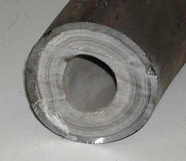
Fig. 1.8 Solid salt scale plug in an Orenburg gas-condensate well, 100 mm diameter. Photo by Yuri F. Makogon, Originally published by PennWell Corporation in Hydrates of Hydrocarbons, 1997 and reprinted with permission.
Another random document with no related content on Scribd: