Radiotherapy in Practice: Imaging for Clinical Oncology
Edited by Peter Hoskin and Vicky Goh
Radiotherapy in Practice: Physics for Clinical Oncology
Edited by Amen Sibtain, Andrew Morgan, Niall MacDougall
Radiotherapy in Practice: Radioisotope Therapy
Edited by Peter Hoskin
Radiotherapy in Practice: External Beam Therapy
THIRD EDITION
Edited by
Peter
Hoskin
Consultant Clinical Oncologist, Mount Vernon Cancer Centre Professor in Clinical Oncology, University of Manchester and Honorary Consultant in Clinical Oncology, University College London Hospitals NHS Trust, London, UK and the Christie Hospital NHS Trust, Manchester UK
Great Clarendon Street, Oxford, OX2 6DP, United Kingdom
Oxford University Press is a department of the University of Oxford. It furthers the University’s objective of excellence in research, scholarship, and education by publishing worldwide. Oxford is a registered trade mark of Oxford University Press in the UK and in certain other countries
The moral rights of the authors have been asserted
First Edition Published in 2006
Second Edition Published in 2012
Third Edition Published in 2019
Impression: 1
All rights reserved. No part of this publication may be reproduced, stored in a retrieval system, or transmitted, in any form or by any means, without the prior permission in writing of Oxford University Press, or as expressly permitted by law, by licence or under terms agreed with the appropriate reprographics rights organization. Enquiries concerning reproduction outside the scope of the above should be sent to the Rights Department, Oxford University Press, at the address above
You must not circulate this work in any other form and you must impose this same condition on any acquirer
Published in the United States of America by Oxford University Press 198 Madison Avenue, New York, NY 10016, United States of America
British Library Cataloguing in Publication Data
Data available
Library of Congress Control Number: 2018962716
ISBN 978–0–19–878675–7
Printed and bound by CPI Group (UK) Ltd, Croydon, CR0 4YY
Oxford University Press makes no representation, express or implied, that the drug dosages in this book are correct. Readers must therefore always check the product information and clinical procedures with the most up-to-date published product information and data sheets provided by the manufacturers and the most recent codes of conduct and safety regulations. The authors and the publishers do not accept responsibility or legal liability for any errors in the text or for the misuse or misapplication of material in this work. Except where otherwise stated, drug dosages and recommendations are for the non-pregnant adult who is not breast-feeding
Links to third party websites are provided by Oxford in good faith and for information only. Oxford disclaims any responsibility for the materials contained in any third party website referenced in this work.
Contents
List of contributors vii
List of abbreviations ix
1 Introduction 1
Peter Hoskin
2 Basic physics 6
Karen Venables
3 Treatment delivery, intensity-modulated radiotherapy, and image-guided radiotherapy 27
Yat Man Tsang
4 Proton therapy 53
Ranald MacKay, Adam Aitkenhead
5 Breast radiotherapy 70
Charlotte Coles, Murray Brunt, Anna Kirby, Sara Lightowlers, Nicola Twyman
6 Radiotherapy for thoracic tumours 115
Kevin Franks, Fiona McDonald, Gerard G Hanna
7 Upper gastrointestinal tract 145
Stephen Falk
8 Rectal cancer 165
Rob Glynne-Jones, Mark Harrison
9 Squamous cell carcinoma of the anus 196
Rob Glynne-Jones, Mark Harrison
10 Prostate cancer 224
Linus Benjamin, Alison Tree, David Dearnaley
11 Bladder cancer 263
Nicholas James, David Fackrell, Anjali Zarkar
12 Testis 279
Peter Hoskin
13 Penis 282
Peter Hoskin
14 Uterus: Endometrium and cervix 288
Melanie Powell, Alexandra Taylor
15 Vulva and vagina 309
Peter Hoskin
16 Lymphomas 317
Richard W Tsang, Mary K Gospodarowicz, Peter Hoskin
17 Central nervous system tumours 351
Neil G Burnet, Fiona Harris, Mark B Pinkham, Kate E Burton, Gillian A Whitfield
18 Head and neck cancer 405
Christopher Nutting, Dorothy Gujral
19 Skin cancer 438
Carie Corner, Hannah Tharmalingam, Peter Hoskin
20 Sarcomas of soft tissue and bone 454
James Wylie
21 Principles of paediatric radiation oncology 468
Henry C Mandeville
22 Radiotherapy planning for metastatic disease 508
Peter Hoskin
23 Quality assurance in radiotherapy 520
Patricia Díez, Edwin GA Aird
Index 537
List of contributors
Edwin GA Aird
Mount Vernon Cancer Centre, Northwood, UK
Adam Aitkenhead
The Christie NHS Foundation Trust & Manchester Cancer Research Centre, Manchester, UK
Linus Benjamin
The Royal Marsden NHS Foundation Trust, London, UK and Mount Vernon Cancer Centre, Northwood, UK
Murray Brunt
University Hospitals of North Midlands NHS Trust, Stoke-on-Trent, UK & Keele University, Keele, UK
Neil G Burnet
University of Manchester, Manchester Cancer Research Centre and The Christie NHS Foundation Trust, Manchester, UK
Kate E Burton
Addenbrooke’s Hospital, Cambridge University Hospitals NHS Foundation Trust, Cambridge, UK
Charlotte Coles
Addenbrooke’s Hospital, Cambridge University Hospitals NHS Foundation Trust, Cambridge, UK
Carie Corner
Mount Vernon Cancer Centre, Northwood, UK
David Dearnaley
The Royal Marsden NHS Foundation Trust, UK
Patricia Díez
Mount Vernon Cancer Centre, Northwood, UK
David Fackrell
Queen Elizabeth Hospital, Birmingham, UK
Stephen Falk
Bristol Oncology Centre, Bristol, UK
Kevin Franks
St James’s Institute of Oncology, Leeds, UK
Rob Glynne-Jones
Mount Vernon Cancer Centre, Northwood, UK
Mary K. Gospodarowicz
Princess Margaret Cancer Centre, University of Toronto, ON, Canada
Dorothy Gujral
Imperial College Healthcare NHS Trust and Imperial College London, London UK
Gerard G. Hanna
UKPeter MacCallum Cancer Centre, Melbourne, Australia
Fiona Harris
Addenbrooke’s Hospital, Cambridge University Hospitals NHS Foundation Trust, Cambridge, UK
Mark Harrison
Mount Vernon Cancer Centre, Northwood, UK
Peter Hoskin
Mount Vernon Cancer Centre, Northwood, and Manchester Cancer Research Centre, University of Manchester, Manchester, UK
Nicholas James Institute of Cancer and Genomic Sciences, University of Birmingham and Queen Elizabeth Hospital, Birmingham, UK
Anna Kirby
Royal Marsden NHS Foundation Trust & Institute of Cancer Research, Sutton, UK
Sara Lightowlers
Addenbrooke’s Hospital,
Cambridge University Hospitals NHS Foundation Trust, Cambridge, UK, and Cambridge University, Cambridge, UK.
Ranald MacKay
The Christie NHS Foundation Trust & Manchester Cancer Research Centre, Manchester, UK
Henry C Mandeville
The Royal Marsden NHS Foundation Trust, London, UK
Fiona McDonald
The Royal Marsden NHS Foundation Trust, London, UK
Christopher Nutting
Royal Marsden Hospital and Institute of Cancer Research, London, UK
Mark B Pinkham
Princess Alexandra Hospital, Brisbane, and University of Queensland, Brisbane, Australia.
Melanie Powell
Barts Health NHS Trust, Barts Institute of Cancer, Barts and The London Medical School, London, UK
Alexandra Taylor
The Royal Marsden NHS Foundation Trust, London, UK
Hannah Tharmalingam
Mount Vernon Cancer Centre, Northwood, UK
Alison Tree
The Royal Marsden NHS Foundation Trust, UK
Yat Man Tsang
Mount Vernon Cancer Centre, Northwood, UK
Richard W Tsang
Princess Margaret Hospital, University of Toronto, ON, Canada
Nicola Twyman
Addenbrooke's Hospital, Cambridge University Hospitals NHS Foundation Trust, Cambridge, UK
Karen Venables
Mount Vernon Cancer Centre, Northwood, UK
Gillian A Whitfield
University of Manchester, Manchester Cancer Research Centre and The Christie NHS Foundation Trust, Manchester, UK
Radiotherapy remains the most important non-surgical treatment in the management of cancer. Over 50% of patients will receive treatment at some time during the management of their malignant disease. In recent years, rapid advances in the technology available to radiotherapy have been made and there is a challenge to the practising clinician to remain abreast of these and harness them to their best use in the management of patients. For most patients receiving radiotherapy this will mean treatment delivered with external X-ray or electron beams. The processes required for the safe delivery of modern radiotherapy comprise a lengthy pathway from treatment decision to treatment delivery and verification. For the more complex treatments this will involve sophisticated immobilization devices, high-precision computed tomography (CT), magnetic resonance imaging (MRI), and positron emission tomography (PET) image-guided volume localization, complex and increasingly accurate physics planning systems with state-of-the-art algorithms to account for tissue inhomogeneities and beam variables, and, finally, the widespread use of high-energy linear accelerators with multileaf collimators (MLCs), the capacity for conformal and intensity-modulated radiation therapy, and the ability to provide on-line image guidance of treatment delivery. Intensity-modulated radiotherapy (IMRT) is now the recognized standard of care for radical treatment, and tomotherapy and stereotactic radiotherapy for more precise high-dose delivery are both widely available. Despite this, however, the basic principles of radiotherapy remain unchanged. Radiotherapy is a loco-regional treatment suitable for radical treatment of tumours in their early stages with high success rates where there has been no metastatic spread. The basic steps of treatment delivery remain: defining the patient position with a means of reproducing that position day to day with appropriate immobilization, followed by accurate localization and definition of the volume to be covered by the high-dose envelope, and then collaboration with medical physicists to identify the optimal means of doing this, using available beams with appropriate modifications. The process of daily implementation of the treatment plan is often neglected but is of vital importance in ensuring accurate and effective radiotherapy together with verification that treatment delivery is reproducing the expected beam as defined in the planning process.
1.2 External beam sources
Linear accelerators are the common source of high-energy X-ray beams producing megavoltage photons of between 4 and 20 million volt energy able to penetrate to the most deep-seated tumours in the largest of patients. Clinically, 4–8 MV beams are the most useful, providing a balance between penetration and adequate surface dose. The fundamental property of megavoltage beams to have skin sparing is both beneficial in terms of reducing skin reaction but also potentially hazardous in reducing the dose to a surface or superficial tumour. Modern linear accelerators are highly sophisticated machines working within a high precision of 2–3%. Recent years have seen widespread implementation of the MLC to provide complex beam shaping and in IMRT applications varying beam transmission. Additional beam modification using motorized wedges has largely replaced the manual wedged-shape filters which used to be placed in the beam by the machine operators. The smooth and reliable running of such machines requires careful maintenance and quality assurance, the importance of which cannot be emphasized too much; it is often carried out unseen and out of hours by the dedicated band of bioengineers and physicists who attend to the processes required to enable safe delivery of radiotherapy to patients.
Particle therapy includes both electron treatment which is widely used for superficial tumours being produced from the standard linear accelerator and proton therapy. The main advantage of protons is that their energy deposition follows the Bragg peak with a high-intensity, highly localized deposition of energy at a fixed depth. This has advantages in the treatment of certain sites, for example, retinal tumours and tumours of the brainstem where highly localized energy deposition avoiding surrounding structures is required. They have also been used in other sites, for example, prostatic carcinoma, as a means of enabling dose escalation within normal tissue tolerance. There are an increasing number of facilities available across the world and in the UK two NHS proton facilities will come on line in the next two years. For this reason proton therapy is now included in some detail in this book.
1.3 Radiotherapy planning
Planning is a critical step in the delivery of clinical radiotherapy. For any treatment to be effective it must be delivered accurately to the region of interest. The identification of the GTV (gross tumour volume), CTV (clinical target volume), and PTV (planning target volume) representing sequential volume expansions from the macroscopic identifiable tumour to including areas where there is risk of tumour spread even if not identified, to a larger volume which takes into account patient movement and other variations in day-to-day set-up of a radiation beam during a fractionated course of treatment is now embedded in the practice of modern radiotherapy. Alongside this, major developments in imaging technology have allowed us to identify tumours with far more accuracy and certainty than before. It is now routine practice to identify internal tumours with CT planning. Increasingly, where appropriate, MRI and PET images are also imported into the planning system and image registration used to provide greater certainty and clarification of the anatomy. Functional
imaging techniques with MRI can enhance this further to provide ever more sophisticated information on the tumour and its surrounding areas, alongside the equally critical identification of the organs at risk where dose should be minimized.
Effective treatment planning ultimately depends upon complex computer algorithms to simulate the effect of a beam passing through the designated area and the amount of radiation energy deposited at any one site. The mathematical accuracy of such algorithms has increased considerably in recent years and combined with the use of CT imaging to provide accurate inhomogeneity data across different tissues, far greater accuracy in dose distribution is now achievable. This is of particular importance where large areas of lung or other air-filled cavities such as the paranasal sinuses are present in the treatment volume.
1.4 Treatment implementation and verification
The delivery of high-dose fractionated radiotherapy requires implementation on the treatment machine of a complex multistep process which may be repeated on a daily basis for 30 or 40 fractions. This presents a significant challenge in devising quality assurance processes to ensure that safe and reproducible radiotherapy is the standard. The increasing use of computerized data sets, with electronic transfer of treatment parameters from the planning software to the linear accelerator, minimizes the risk of human error in transferring data. The use of mechanized wedges and MLCs takes out the risk of the machine operator placing the wrong wedge in position or when using lead shielding on a lead tray having this wrongly positioned. The importance of immobilization to reproduce patient set-up is now widely recognized and facilitated by the use of immobilization devices ranging from simple head shells and vacuum bags to stereotactic frames.
The megavoltage beams used for radiotherapy produce images have poor definition between bone and soft tissue and are therefore more difficult to interpret than kilovoltage (kV) energy beams. The advent of modern linear accelerators with silicone diode array detectors, electronic portal imaging devices, and on-board kV imaging equipment has greatly enhanced the ability to accurately verify beam position. Many patients are now treated with implanted fiducial markers in the treatment region to improve identification with radiotherapy imaging. More frequent validation with electronic portal imaging devices can be achieved and presentation of these on the computer screen alongside the planning images with software tools to facilitate comparison greatly improves the accuracy of treatment and enables systematic errors to be readily identified and corrected.
A further development is the incorporation of an MRI imaging facility within the linear accelerator, the MR linac, which will enable on line verification with MRI.
1.5 Radiation dose prescriptions
Radiotherapy prescriptions have long carried an air of mystery and confusion. This is hardly surprising when three or four different total doses given in a variation of fractions of treatment over differing times are recommended for exactly the same
tumour. Much of this relates to history and legend rather than systematic evaluation. The problem is now compounded by new concepts in which acceleration of fractions is recommended by some, hyperfractionation by others, use of a concomitant boost by yet others, whilst in most centres daily fractionation Monday to Friday remains the standard. For radical treatment, the following schedules may be encountered:
◆ Conventional fractionation usually refers to daily treatment on a Monday to Friday basis.
◆ Accelerated fractionation means that the overall total dose is given in a shorter time than would be achieved with conventional fractionation. This results in greater toxicity and therefore only limited acceleration is possible without altering fraction size. An example of this is the DAHANCA regimen in which six fractions are given over 5 days so that a conventional 6-week treatment schedule is delivered in 5 weeks. This modest acceleration has been shown to improve the results in head and neck cancer.
◆ Hyperfractionation refers to the practice of reducing the fraction size of a conventional regimen, often delivering treatment twice or even three times a day in the smaller fraction sizes to enable a higher dose overall to be delivered. This is possible because the toxicity, in particular the late toxicity, is reduced when the fraction size is reduced for a given total dose. This approach has been investigated in many sites including head and neck cancer and non-small cell lung cancer.
◆ CHART (continuous hyperfractionated accelerated radiotherapy) is a schedule which encompasses both acceleration and hyperfractionation delivering the total dose in a shorter overall time (acceleration) and in smaller individual fractions (hyperfractionation). The original CHART schedule delivered 54 Gy in 36 fractions of 1.5 Gy over 12 days.
◆ Hypofractionation refers to giving a treatment in a shorter time than conventional treatment using bigger doses per day and in order to do so safely reducing the total dose. In the radical setting, examples are the delivery of 55 Gy in 20 daily fractions or 50 Gy in 16 daily fractions which are considered equivalent to a radical conventional dose of 65 Gy in 6½ weeks. There is increased interest in such schedules following the observation that some tumours such as prostate cancer may have radiation response characteristics with low alpha/beta ratios. As a result, large doses per fraction are biologically more effective. Concerns relating to normal tissue effects even with highly accurate IMRT remain; hence formal evaluation in randomized trials are now complete.
◆ Palliative radiotherapy is one area where hypofractionation is indicated. In symptom control the aim is not to deliver a high dose to eradicate tumour but a sufficient dose to enable symptom control. It has been widely shown that single doses of 8 Gy or thereabouts are sufficient to improve bone pain and single doses of 10 Gy will improve symptoms from non-small cell lung cancer. Other common schedules in use for palliation are 21 Gy in three fractions, 20 Gy in five fractions, and 30 Gy in 10 fractions.
The third edition of this book continues its aim to provide a practical guide to the use of external beam radiotherapy incorporating the substantial technological advances that have been made in recent years. It will provide a firm background in the physics of external beam radiotherapy and then deals with each anatomical site in turn with details of the indications and techniques used for radiotherapy delivery.
Chapter 2
Basic physics
Karen Venables
2.1 Introduction
The distribution of radiation within the patient will be affected by many factors. These include the energy and modality of the beam, the density of the tissue, the use of beam modifiers such as wedges and compensators, and the distance of the patient from the machine. The apparent distribution will also be affected by the accuracy of the algorithm used on the planning system.
2.2 Interaction processes
The deposition of dose within the patient is dependent on the interaction process or processes involved. Dose is the energy deposited in the material as a result of interactions of photons and electrons with the material. When photons undergo an interaction, energy is transferred to electrons, which will then deposit their energy in the medium. At low energies, photons interact predominantly by the photoelectric effect in which a tightly bound electron is ejected from the atom. The dominant interaction process in tissue for photons produced from linear accelerators (1–20 MeV) is the Compton process whereby the photon interacts with a loosely bound electron, resulting in a free electron and a scattered photon of reduced energy. Pair production also occurs above 1.02 MeV whereby a photon interacts within the nucleus of the atom producing an electron and a positron; the positron will travel a short distance and then annihilate, producing two further photons of energy 0.511 MeV. In contrast to photons in which the probability of an interaction occurring is governed by a chance process, electrons deposit energy continuously along the length of their path by collision with atomic electrons. They also lose energy through Bremsstrahlung: when electrons pass close to a nucleus (which has a positive charge), it attracts the negatively charged electron, changing its direction, and an X-ray photon is emitted. The range of an electron in a medium is dependent upon its initial energy and the density of material through which it is traveling. Interactions produced from photon beams are illustrated in Fig. 2.1. Monte Carlo is a powerful computing tool for determining the result of irradiating a material with a beam of photons or electrons. It uses statistical methods to determine the outcome of interactions and can be used to follow the history of individual particles in a beam. It is used in some treatment planning system (TPS) algorithms to generate dose at a point. Diagrams illustrating the deposition of dose are shown in Figs 2.2–2.7. The deposition of dose within a medium can be described by a dose deposition kernel.
(a)
Incident Photon
Characteristic X-rays (photons with energy determined by the atomic energy levels)
Ejected electron
(b)
Incident Photon
Electron
Scattered photon
Annihilation photons (c)
Incident Photon
Electron positron
Fig. 2.1 Photon interaction processes. (a) Photoelectric effect: the incident photon interacts with a bound electron which is ejected from the atom. Other electrons of higher energy take its place and their excess energy is emitted as characteristic X-rays. (b) Compton effect: the incident photon interacts with a loosely bound electron producing a scattered photon and scattered electron. (c) Pair production: the incident photon interacts with the nucleus of the atom.
2.3 Dose deposition within the patient
The penetration of X-rays or electrons will be dependent on the effective accelerating potential to which the electrons in the waveguide have been subjected, although the design of the treatment machine head will also affect this and photons or electrons with a nominal beam energy from one machine may not have the same properties as those with the same nominal energy from another machine. The photons incident on the patient will have a spectrum of energies with the maximum possible energy being that of the accelerating potential. The mean energy will be much lower, usually ¼ to ⅓ of the maximum.
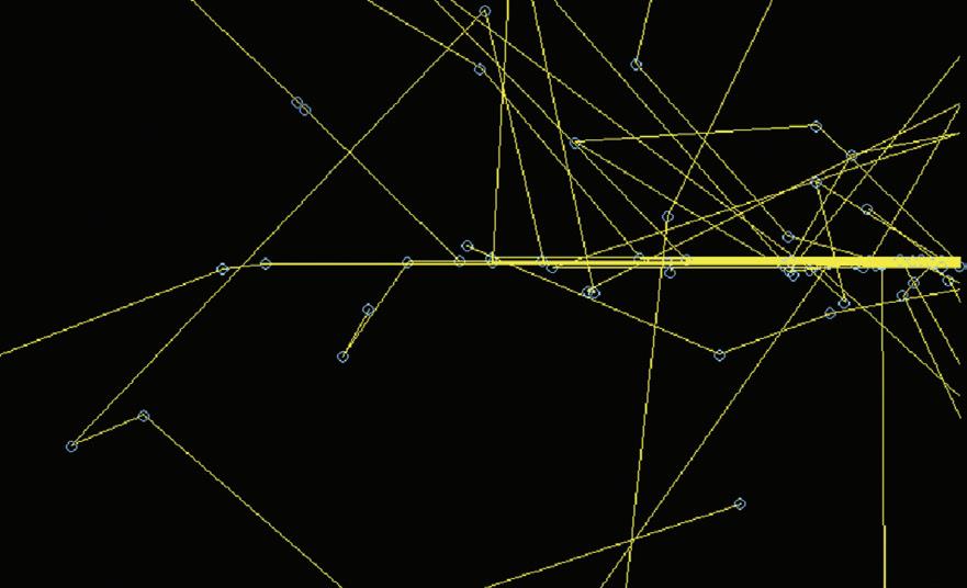
Fig. 2.2 Monte Carlo calculation of twenty-five 100 kV photons incident on a 20-cm water slab. The yellow lines (e.g. 1) show the photon and the blue circles (e.g. 2) the electrons. At this energy, the electron range is below the resolution of the diagram and their energy is absorbed at the points of interactions. All of the photons interact before leaving the slab and a number have been scattered back towards the surface (e.g. 3). Large angle scattering is common (e.g. 4).
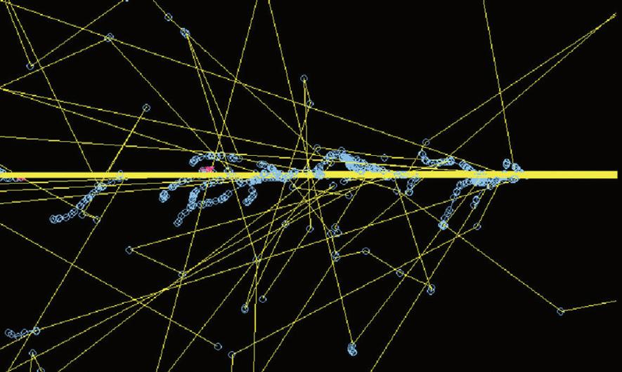
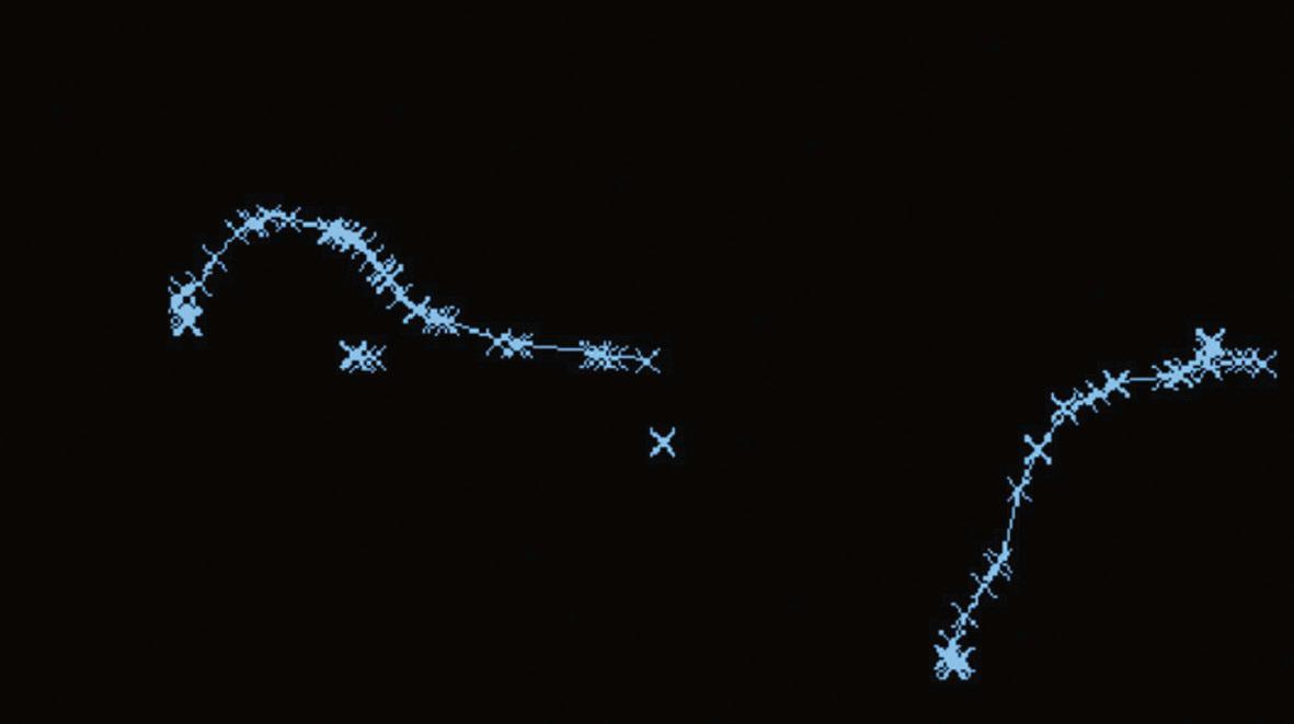
Fig. 2.3 Monte Carlo calculation of twenty-five 6- MV photons incident on a 20-cm water slab. The yellow lines show the photons, the blue lines and circles the electrons, and the red lines and crosses the positrons. Most of the electrons travel a short distance before losing their energy and being reabsorbed but as shown by the number of blue circles, they interact many times each time losing a little of their energy, in contrast to the photons most of which travel a much larger distance between interactions. Some of the photons do not interact before leaving the slab and the number scattered back towards the surface is reduced compared to the 100 kV beam. Pair production is possible at this energy as illustrated by the production of a positron (1) which travels a short distance before annihilating. Compton interactions are governed by chance and dependent upon energy; for the photons shown in this diagram no photon interactions occurred in the first 2.5 cm, and this explains the build-up in dose that occurs for high energy accelerators. before dose can be deposited, the photons must have interacted, electrons produced in photon interactions gradually deposit dose along their path length.
Photon beam
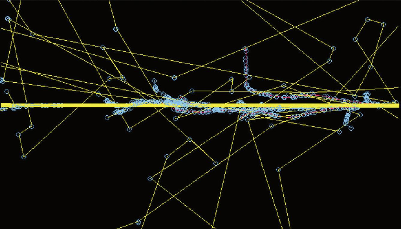
Fig. 2.4 Monte Carlo calculation of twenty-five 20 MV photons incident on a 20-cm water slab. The yellow lines show the photons, the blue lines and circles the electrons, and the red lines and crosses the positrons. Some of the photons do not interact before leaving the slab and the scattered photons and electrons are predominately in the same direction as that of the incident photon. There is an increase in pair production and the positrons travel further before being annihilated. Many of the photons outside of the beam are the result of this process (e.g. the track traced in green is the result of a single annihilation process).
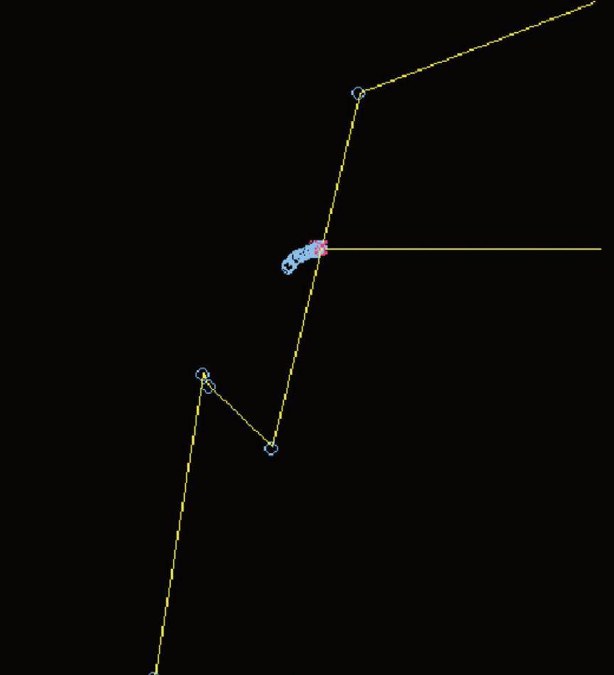
Fig. 2.5 Monte Carlo simulation of a positron from 6-MV beam, showing the two 511 keV photons almost in opposing directions (e.g. 1), the positron (e.g. 2), and electron (e.g. 3)
Water surface
Photon beam
Fig. 2.6 Monte Carlo simulation showing electrons produced from interactions of 6 MV photons. Note the tortuous paths and the increased number of interactions (each shown by a blue cross) as the electron reaches the end of its range and has only a low energy.
The deposition of dose within a material is often described in terms of either percentage depth dose or tissue phantom ratios (TPRs). Percentage depth dose values relate the dose at a given depth to that at the depth of maximum dose for the same distance of the radiation source to the surface. They are dependent on the treatment machine energy, distance from the source, and irradiated area, as well as the material in which the dose is deposited. TPRs relate the dose at a reference depth in a phantom to the dose at a point the same distance from the source but with a different depth of material above the point. Tissue maximum ratios are a special case of TPR where the reference depth is taken to be the depth at which maximum dose is deposited. TPRs are dependent on field size, machine energy, and material in which the dose is deposited but have only a very small dependence on distance from the source of radiation. TPRs are often used for quick calculation of isocentric treatments, whereas percentage depth doses are preferred in centres that treat patients at a fixed focus to surface distance. This is illustrated in Fig. 2.8.
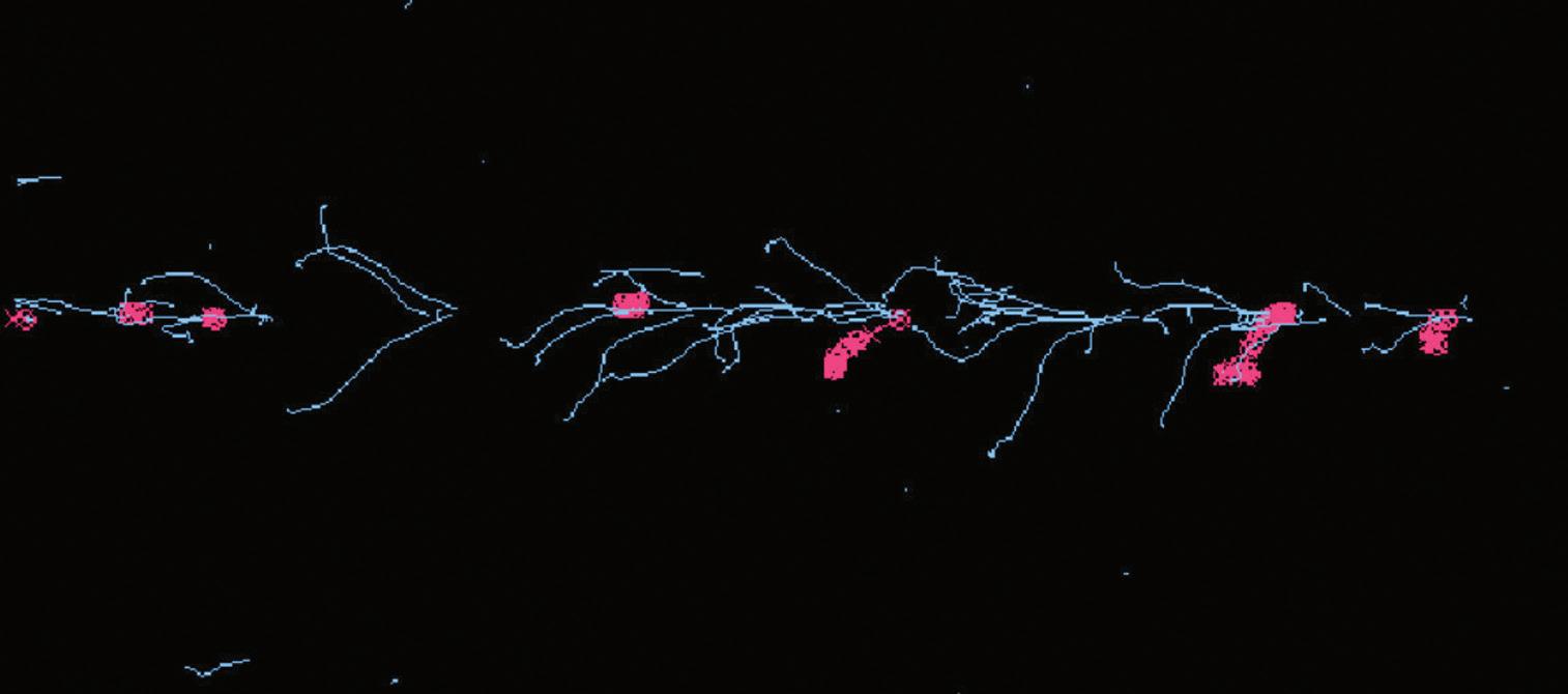
Fig. 2.7 Monte Carlo simulation of a narrow beam of a hundred 6 MV photons on a water phantom, illustrating that most of the electrons deposit their energy close to the position of the track of the incident photon beam. Generation of pencil beams for planning systems using Monte Carlo calculated pencil beams is performed in this way and the resultant dose distribution characterized. In the case of planning system pencil beams, the incident photon beam is not a single energy but a spectrum of energies to represent those found clinically in linear accelerator beams.
Photon beam
Fig. 2.8 Diagram to illustrate the difference between percentage depth dose and TPR. The percentage depth dose at point A would be found by dividing the dose at A by the dose at b and multiplying by 100 to convert to a percentage. In contrast, the TPR for a depth of D would be found by dividing the dose measured at T and dividing by the dose measured at S. Note that in both the above cases, the same field size (jaw settings) has been used throughout. The variation of the machine output with field size must also be incorporated.
2.4 Sources of high energy X-rays
Historically patients were treated with orthovoltage and superficial X-ray units (up to 300 kV). These deliver high dose to the surface whilst still contributing dose at depth. They are still used to treat some superficial lesions, particularly in the head and neck region. Cobalt 60 machines were developed in the 1950s and deliver a higher dose at depth due to the energy of the photons (1.17 MeV and 1.33 MeV). They are usually reliable machines and still have a place in a few radiotherapy departments for simple treatments. The photons are produced from the radioactive decay of the source. The strength of the source (and therefore the intensity of the radiation) decreases with time. The source must be changed approximately every 5 years to prevent treatment times becoming too long. Depth dose curves for these machines are shown in Fig. 2.9. Modern high-energy linear accelerators offer a choice of photon and electron energies. The production of high-energy photons can be described briefly as follows. Electrons are emitted from the heated gun filament, and their energy is gradually increased as they move through the waveguide, transported by high-power radio waves. The beam of electrons is focused and steered through an angle of between 90° and 270° (depending on manufacturer’s design) (if necessary) to hit a high atomic number target. The resultant X-ray beam is collimated and the intensity of the radiation modulated using a metal cone, known as the flattening filter, which is thickest in the centre to produce a beam with a near uniform intensity within the treatment machine head. The beam is collimated using two pairs of diaphragms or one pair of diaphragms and
Fig. 2.9 Depth–dose curves for superficial and orthovoltage units. The 100 kV curve is for a 30-cm focus-to-skin distance (fSD) unit, with half-value layer (HVL) of 3 mm and a 10-cm diameter field, the 230 kV curve is for a 50-cm fSD unit with an HVL of 2-mm Cu and a closed end applicator, field size 10×10 cm. The Cobalt 60 data is for an fSD of 80 cm and a field size of 10×10 cm.
a set of multileaf collimator (MLC) leaves. The components of the conventional linear accelerator are illustrated in Fig. 2.10.
Speciality linacs vary this basic design, both tomotherapy and cyberknife use compact linacs with shorter waveguides which can still operate at about 6 MV. In tomotherapy units, the linac is mounted on a computed tomography-type gantry system and the collimation is provided by a binary MLC (leaves are either open or closed at any point in time). In cyberknife, the linac is fitted to a robotic arm allowing many degrees of freedom in the direction in which the radiation can enter the patient. Collimation is provided by a selection of fixed collimators from 0.5 cm to 6 cm radius or a variable aperture collimator. Both of these linacs operate without a flattening filter and at higher dose rates than a standard accelerator.
Electron beams used for treatment can be produced either by rapidly scanning the narrow beam of electrons across the desired area or more commonly the beam is broadened by the use of a scattering foil in place of the X-ray target. In normal use, a series of openings in an electron ‘applicator’ are used to collimate the beam down to or close to the patient’s skin.
Typical depth dose curves for photons and electrons are shown in Figs 2.11 and 2.12. Dose is not deposited directly by the photons but rather by electrons set in motion through interaction processes; therefore, for megavoltage photons, the maximum dose (dmax) does not occur at the surface but at a depth of 1–4 cm. The number of photons in the beam will begin to decrease immediately the beam enters the patient; however, even those photons that interact in the first millimetre of tissue will
Bending magnet
Target
Primary collimators
Ionization
Backscatter plate
Y jaws
X jaws
End plate MLC
Fig. 2.10 block diagram showing the components of a linear accelerator.
set in motion electrons which will travel a short distance before they have deposited all of their energy. A ‘build-up effect’ occurs with increasing dose deposited with depth until a condition is met whereby the energy transferred to electrons generated from interactions is matched by the energy deposited by electrons already set in motion. The dose at the surface is typically between 10% and 30% of the dose at dmax,
de pth do se
Fig. 2.11 Percentage depth dose curves for 6 and 15 MV photon beams at 100-cm fSD, 10×10 cm.
Electron gun Accelerating waveguide
Electron depth dose curves.
dependent on beam energy, field size, linac design, and the presence of scattering materials such as wedges in the beam. The depth at which the maximum dose occurs is dependent primarily on the beam energy. After dmax, a gradual decrease in the dose deposited occurs as the number of photons in the beam is reduced. Two effects contribute to this: the reduction in intensity due to the larger area that the photons cover as the distance is increased and the decrease due to attenuation. For a very narrow beam of monoenergetic photons, at a large distance from the source, the decrease due to attenuation would be exponential. Deviations from exponential decrease occur for two reasons: the beams from linear accelerators are not monoenergetic but comprise a spectrum of radiation and for the majority of cases in radiotherapy a broad beam is used and therefore scatter from the medium will also affect the beam intensity. The irradiated area will affect the number of scattered photons generated. As the field size is increased from zero, there is initially a rapid increase in dose to a point at the centre of the beam. This rate of increase slows as larger field sizes are reached.
In contrast to photons, electron beams begin to deposit energy immediately on entering the patient. There is a small build-up as the electrons will travel a short distance before finally being absorbed into the medium. The range of electrons within tissue will determine the distance into the material which they can penetrate and once this distance has been reached there is a rapid decrease in the depth dose curve, beyond which the only significant dose deposited is that from contaminant photons within the beam. In contrast to photons, correcting the intensity of a beam of electrons using the inverse square law is complex, as the source of electrons will not be the radiation target but an effective scatter source within the accelerator head. It is usually advisable to measure outputs at non- standard distances.
The radial profile of the beam is dependent primarily on the shape of the flattening filter. When the machine is purchased, a depth for which the beam
Fig. 2.12
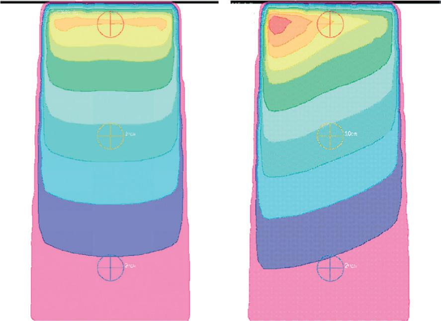
Fig. 2.13 (a) Isodose distribution for a 10×10 field incident on a water phantom at 100cm fSD. Note the change in shape of the isodose lines as the depth is increased. At 3-cm deep, the 95% isodose is deeper at the outside of the beam, in contrast to this at approximately 15-cm deep, the 50% isodose is deepest at the centre of the beam. (b) A 25° wedge field also incident on a flat water phantom.
intensity will be uniform is stated and the manufacturer will make any required adjustments to the flattening filter. This depth is typically 5 or 10 cm. For large field sizes, at shallower depths, the profile will have ‘horns’ or areas of increased intensity whereas at greater depths the intensity at the edges of the beam are decreased. Two factors contribute to this: a non-equilibrium of scatter from the edge of the beam and a small change in mean energy as the distance from the centre of the field is increased. The energy change is caused by absorption of low energy photons at the flattening filter. In the centre where the filter is thickest, more low energy photons will be absorbed in comparison with the edges of the field. This absorption of low energy photons is often referred to as ‘beam hardening’. This is adequately accounted for by most planning systems and can be seen on the isodose distribution shown in Fig. 2.13.
2.5 Radiation distributions within the patient
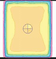
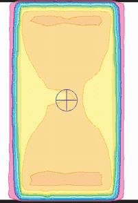
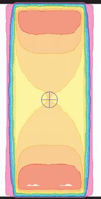
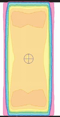
Some patients may be treated using either a single field or a parallel-opposed pair. The appropriateness of each of these is related to the patient size and the location of the tumour. Distributions for a range of patient sizes for 6 MV are shown in Fig. 2.14. For separations of 12 cm, two opposing beams produce a uniform distribution of radiation through the patient. As the patient separation is increased, areas of increased dose relative to the dose at the centre of the volume are seen towards the surface. For a patient separation of 24 cm, these areas reach 114% of the dose at the centre and the use of higher energy beams should be considered to give a more even dose distribution.
Fig. 2.14 Radiation distribution for a parallel opposite 6 MV beam for patient separations of 12 cm, 18 cm, and 24 cm, and for a parallel-opposed 15 MV beam for a patient separation of 24 cm. for the higher-energy beam the depth of the high-dose areas are more interior.
2.6 Machine dependent factors affecting the dose deposition
2.6.1
Field size effects
As the radiation field size is increased, the amount of radiation to a point on the central axis per monitor unit increases. The major cause of this is an increase in the contribution of scattered radiation both from within the treatment machine head and within the patient. This will affect the depth dose curves; the depth of dmax will decrease and the percentage depth dose at depth will increase compared to a smaller field size. Measurements of the relative output at different field sizes and of appropriate isodose distributions are performed during commissioning. When irregular field shapes such as those produced by MLCs are used, the contribution of scatter is more difficult to assess and individual calculations for each patient may be necessary.
2.6.2
Effect of distance
As the distance of the patient from the accelerator is increased, the intensity of the radiation at the surface will decrease due to the inverse square law, the irradiated area will increase due to the beam divergence, and the penetration of the radiation will increase due to a reduction in low energy photons in the beam. The increased area is utilized in treatments such as total body irradiation where the patient is placed at an increased distance (typically 4 m) from the machine. A slightly increased mean energy may be noticed for example when changing from a Cobalt machine with an isocentre at 80 cm to one with an isocentre at 100 cm. The effect for a 6 MV beam is shown in Fig. 2.15.
2.7 Modifications to the radiation beam
2.7.1
Wedges
The intensity of the radiation can be modified by the presence of a wedge. These are used for multifield plans to compensate for the weighting of other fields, for example in the treatment of the parotid or the prostate. They can also be used to compensate
Fig. 2.15 Photon depth dose curves for 6 MV photons at different focus to surface distances.
for missing tissue as in the case of breast radiotherapy, or low-density tissue in part of the field as for lung treatments. Examples of typical plans for these sites are given in the appropriate chapters. Three types of wedge are in current use:
◆ Manually fitted wedges which are usually external to the treatment head.
◆ Steep internal wedges which are driven in and out of the beam by a motor.
◆ Dynamic wedges where the jaw moves across the field partway through the treatment reducing the beam intensity to give an appropriate profile, as illustrated in Fig. 2.16.
The definition of wedge angle has changed over time as the design of accelerators has changed. One definition of wedge angle is the angle between the central axis of the beam and the normal to the 50% isodose. Motorized internal wedges are typically approximately 60° and are combined with an open field of the same size to produce different effective wedge angles. Internal and dynamic wedges have the advantage that they do not have to be manually lifted by the treatment unit staff reducing staff injuries and these are now present in the majority of machines. Physical wedges (either internal or external) will change the penetration of the beam on the central axis as well as modifying the radiation profile, whereas dynamic wedges do not change the penetration of the beam on the central axis. External wedges can also increase the patient surface dose slightly due to the production of scattered radiation.
2.7.2 Multi-leaf collimators
These are used to shape the radiation beam to protect organs at risk or to modify the intensity of the beam by using a segment field as simple intensity-modulated radiotherapy (IMRT). The width of the MLC leaves varies between machines, high resolution MLCs used in stereotactic work have a width of 2–3 mm projected at isocentre, whereas other designs of accelerator have leaves which are 10 mm projected at isocentre.