Immediate download Joint structure and function a comprehensive analysis 5th edition, (ebook pdf) eb
Visit to download the full and correct content document: https://ebookmass.com/product/joint-structure-and-function-a-comprehensive-analysi s-5th-edition-ebook-pdf/
More products digital (pdf, epub, mobi) instant download maybe you interests ...
Multilayer Networks: Structure and Function Ginestra Bianconi
The fifth edition of Joint Structure and Function is made possible only by the continued and combined efforts of many people and groups. We are, first and foremost, grateful for the time, effort, and expertise of our esteemed contributors with whom it has been a pleasure to work. Our thanks, therefore, to Drs. Sam Ward, Sandra Curwin, Gary Chleboun, Diane Dalton, Julie Starr, Pam Ritzline, Paula Ludewig, John Borstad, RobRoy Martin, Lynn Snyder-Mackler, Michael Lewek, Erin Hartigan, Janice Eng, and Sandra Olney, as well as to Ms. Noelle Austin and Mr. Benjamin Kivlan. Additionally, we want to express our appreciation to the individuals who helped develop the ancillary materials that support the fifth edition, including the Instructor’s Resources developed by Ms. Christine Conroy and the videos developed by Dr. Lee Marinko and Center City Film & Video. We would also like to acknowledge and thank the individuals who contributed their comments and suggestions as reviewers (listed on page xi), as well as those who passed along their unsolicited suggestions through the years, including our students.
We extend our continuing gratitude to F. A. Davis for their investment in the future of Joint Structure and Function and its ancillary materials. Particular thanks go to Margaret Biblis (Publisher), Melissa Duffield (Acquisitions Editor), Karen Carter (Developmental Editor), Yvonne Gillam (Developmental Editor), George Lang (Manager of Content Development), David Orzechowski (Managing Editor), Robert Butler (Production Manager), Carolyn O’Brien (Manager of Art and Design), Katherine Margeson (Illustration Coordinator), and Stephanie Rukowicz (Assistant Developmental Editor) who provided great support. As always we must thank the artists who, through the years, provided the images that are so valuable to the readers. These include artists of past editions, Joe Farnum, Timothy Malone, and Anne Raines. New to the fifth edition is Dartmouth Publishing, Inc., adding both new figures and enhanced color to the text.
Finally, we acknowledge and thank our colleagues and families, without whose support this work could not have been done and to whom we are eternally indebted.
CONTRIBUTORS
Noelle M. Austin, PT, MS, CHT
CJ Education and Consulting, LLC Woodbridge, Connecticut www.cj-education.com The Orthopaedic Group Hamden, Connecticut
John D. Borstad, PT, PhD Assistant Professor Physical Therapy Division Ohio State University Columbus, Ohio
Gary Chleboun, PT, PhD Professor School of Physical Therapy Ohio University Athens, Ohio
Sandra Curwin, PT, PhD Associate Professor School of Physiotherapy Dalhousie University Halifax, Nova Scotia, Canada
Diane Dalton, PT, DPT, OCS Clinical Assistant Professor Physical Therapy Program Boston University Boston, Massachusetts
Janice J. Eng, PT, OT, PhD Professor Department of Physical Therapy University of British Columbia Vancouver, British Columbia, Canada
Erin Hartigan, PT, PhD, DPT, OCS, ATC Assistant Professor Physical Therapy Department University of New England Portland, Maine
Benjamin Kivlan, PT, SCS, OCS, CSCS Doctoral Student Duquesne University Pittsburgh, Pennsylvania
Michael Lewek, PT, PhD Assistant Professor Division of Physical Therapy University of North Carolina at Chapel Hill Chapel Hill, North Carolina
Paula M. Ludewig, PT, PhD Associate Professor Program in Physical Therapy University of Minnesota Minneapolis, Minnesota
RobRoy L. Martin, PT, PhD, CSCS Associate Professor Duquesne University Pittsburgh, Pennsylvania
Sandra J. Olney, PT, OT, PhD Professor Emeritus School of Rehabilitation Therapy Queens University Kingston, Ontario, Canada
Pamela Ritzline, PT, EdD Associate Professor Department of Physical Therapy University of Tennessee Health Science Center Memphis, Tennessee
Lynn Snyder-Mackler, PT, ScD, SCS, ATC, FAPTA
Alumni Distinguished Professor Department of Physical Therapy University of Delaware Newark, Delaware
Julie Ann Starr, PT, DPT, CCS Clinical Associate Professor Physical Therapy Program Boston University Boston, Massachusetts
Sam Ward, PT, PhD
Departments of Radiology, Orthopaedic Surgery, and Bioengineering University of California San Diego La Jolla, California
REVIEWERS
John H. Hollman, PT, PhD Director and Assistant Professor, Program in Physical Therapy
Department of Physical Medicine and Rehabilitation Mayo Clinic College of Medicine Rochester, Minnesota
Chris Hughes, PT, PhD, OCS, CSCS Professor Graduate School of Physical Therapy Slippery Rock University Slippery Rock, Pennsylvania
Leigh K. Murray, PT, PhD Assistant Professor Physical Therapy Department Walsh University North Canton, Ohio
William K. Ogard, PT, PhD Assistant Professor Physical Therapy Department University of Alabama at Birmingham Birmingham, Alabama
Suzanne Reese, PT, MS Associate Professor Physical Therapist Assistant Program Tulsa Community College Tulsa, Oklahoma
Nancy R. Talbott, PhD, MS, PT Associate Professor Rehabilitation Sciences University of Cincinnati Cincinnati, Ohio
David P. Village, MS, PT, DHSc Associate Professor Department of Physical Therapy Andrews University Berrien Springs, Michigan
Krista M. Wolfe, DPT, ATC Director, Physical Therapy Assistant Program Allied Health Department Central Pennsylvania College Summerdale, Pennsylvania
Linda L. Wright, PhD, PT Professor, Department of Physical Therapy Director, Educational Technology College of Health Professions Armstrong Atlantic State University Savannah, Georgia
CONTENTS IN BRIEF
SECTION 1.
Joint Structure and Function: Foundational Concepts2
Sandra J. Olney, PT, OT, PhD, and Janice Eng, PT, OT, PhD INTRODUCTION525
GaitAnalysis525
MajorTasksofGait525
PhasesoftheGaitCycle525
GAITTERMINOLOGY527
TimeandDistanceTerms527
KinematicTerms528
KineticTerms529
Electromyography531
CHARACTERISTICS OFNORMALGAIT532
TimeandDistanceCharacteristics532
SagittalPlaneJointAngles532
FrontalPlaneJointAngles534
GroundReactionForce andCenterofPressure534
SagittalPlaneMoments535
FrontalPlaneMoments537
SagittalPlanePowers540
FrontalPlanePowers542
MechanicalEnergyofWalking542
MuscleActivity545
GaitInitiationandTermination550
TRUNKANDUPPER
TREADMILL,STAIR, ANDRUNNINGGAITS553
TreadmillGait553
StairGait553
ABNORMALGAIT561
StructuralImpairment562
FunctionalImpairment562
Summary564
StudyQuestions564 References564 Index569
Joint Structure and Function FIFTH
EDITION
A Comprehensive Analysis
Section
Joint Structure and Function: Foundational Concepts
Chapter 1 Biomechanical Applications to Joint Structure and Function
Chapter 2 Joint Structure and Function
Chapter 3 Muscle Structure and Function
Biomechanical Applications to Joint Structure and Function
SamuelR.Ward,PT,PhD
“Humans
have the capacity to produce a nearly infinite variety of postures and movements that require the tissues of the body to both generate and respond to forces that produce and control movement.”
Introduction
PART 1:KINEMATICS AND INTRODUCTION TO KINETICS
Descriptions of Motion
TypesofDisplacement
Translatory Motion
Rotary Motion
General Motion
LocationofDisplacementinSpace
DirectionofDisplacement
MagnitudeofDisplacement
RateofDisplacement
Introduction to Forces
DefinitionofForces
ForceVectors
ForceofGravity
Segmental Centers of Mass and Composition of Gravitational Forces
Center of Mass of the Human Body
Center of Mass, Line of Gravity, and Stability
Alterations in Mass of an Object or Segment
Introduction to Statics and Dynamics
Newton’sLawofInertia
Newton’sLawofAcceleration
Translatory Motion in Linear and Concurrent Force
Systems
LinearForceSystems
Determining Resultant Forces in a Linear Force System
ConcurrentForceSystems
Determining Resultant Forces in a Concurrent Force System
Newton’sLawofReaction
Gravitational and Contact Forces
Additional Linear Force Considerations
TensileForces
Tensile Forces and Their Reaction Forces
JointDistraction
Distraction Forces
Joint Compression and Joint Reaction Forces
RevisitingNewton’sLawofInertia
Vertical and Horizontal Linear Force Systems
ShearandFrictionForces
Static Friction and Kinetic Friction
Considering Vertical and Horizontal Linear Equilibrium
Continued
PART 2:KINETICS—CONSIDERING ROTARY AND TRANSLATORY FORCES AND MOTION
Torque, or Moment of Force
AngularAccelerationandAngularEquilibrium
ParallelForceSystems
Determining Resultant Forces in a Parallel Force System
Bending Moments and Torsional Moments
Identifying the Joint Axis About Which Body Segments
Rotate
MeetingtheThreeConditionsforEquilibrium
Muscle Forces
TotalMuscleForceVector
Anatomic Pulleys
Anatomic Pulleys, Action Lines, and Moment Arms
Torque Revisited
ChangestoMomentArmofaForce
AngularAccelerationWithChangingTorques
MomentArmandAngleofApplicationofaForce
INTRODUCTION
Humans have the capacity to produce a nearly infinite variety of postures and movements that require the structures of the human body to both generate and respond to forces that produce and control movement at the body’s joints. Although it is impossible to capture all the kinesiologic elements that contribute to human musculoskeletal function at a given point in time, knowledge of at least some of the physical principles that govern the body’s response to active and passive stresses is prerequisite to an understanding of both human function and dysfunction.
We will examine some of the complexities related to human musculoskeletal function by examining the roles of the bony segments, joint-related connective tissue structure, and muscles, as well as the external forces applied to those structures. We will develop a conceptual framework that provides a basis for understanding the stresses on the body’s major joint complexes and the responses to those stresses. Case examples and clinical scenarios will be used to ground the reader’s understanding in relevant applications of the presented principles. The objective is to cover the key biomechanical principles necessary to understand individual joints and their interdependent functions in posture and locomotion. Although we acknowledge the role of the neurological system in motor control, we leave it to others to develop an understanding of the theories that govern the roles of the controller and feedback mechanisms.
This chapter will explore the biomechanical principles that must be considered to examine the internal and external forces that produce or control movement. The focus will be largely on rigid body analysis; the next two chapters explore how forces affect deformable connective tissues (Chapter 2) and how muscles create and are affected by
Lever Systems, or Classes of Levers
MusclesinThird-ClassLeverSystems
MusclesinSecond-ClassLeverSystems
MusclesinFirst-ClassLeverSystems
MechanicalAdvantage
Trade-Offs of Mechanical Advantage
LimitationsofAnalysisofForcesbyLeverSystems Force Components
Force Components and the Angle of Application of the Force
TranslatoryEffectsofForceComponents
RotaryEffectsofForceComponents
Rotation Produced by Perpendicular (Fy) Force Components
Rotation Produced by Parallel (Fx) Force Components
Multisegment (Closed-Chain) Force Analysis
forces (Chapter 3). Subsequent chapters then examine the interactive nature of force, stress, tissue behaviors, and function through a regional exploration of the joint complexes of the body. The final two chapters integrate the function of the joint complexes into the comprehensive tasks of posture (Chapter 13) and gait (Chapter 14).
In order to maintain our focus on clinically relevant applications of the biomechanical principles presented in this chapter, the following case example will provide a framework within which to explore the relevant principles of biomechanics.
1-1 Patient Case
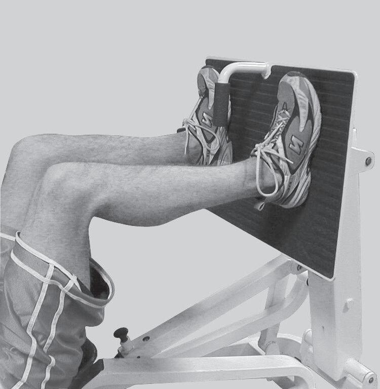
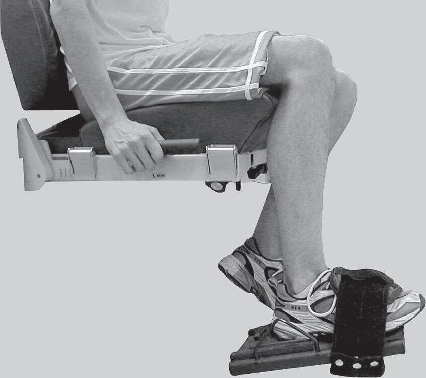
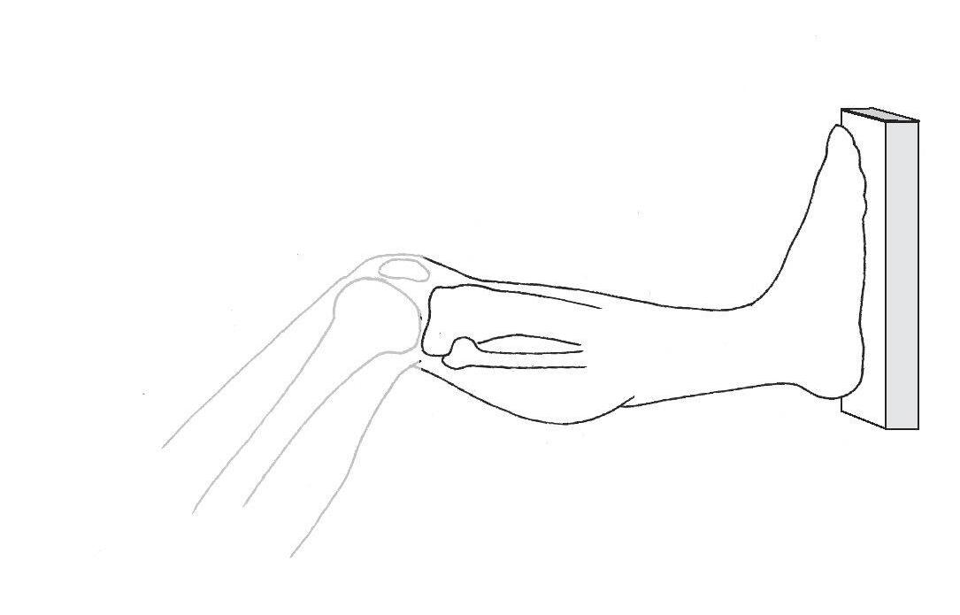
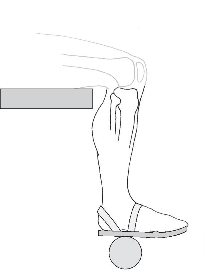
John Alexander is 20 years old, is 5 feet 9 inches (1.75 m) in height, and weighs 165 pounds (~75 kg or 734 N). John is a member of the university’s lacrosse team. He sustained an injury when another player fell onto the posterior-lateral aspect of his right knee. Physical examination and magnetic resonance imaging (MRI) resulted in a diagnosis of a tear of the medial collateral ligament, a partial tear of the anterior cruciate ligament (ACL), and a partial tear of the medial meniscus. John agreed with the orthopedist’s recommendation that a program of knee muscle strengthening was in order before moving to more aggressive options. The initial focus will be on strengthening the quadriceps muscle. The fitness center at the university has a leg-press machine (Fig. 1–1A) and a free weight boot (see Fig. 1–1B) that John can use.
As we move through this chapter, we will consider the biomechanics of each of these rehabilitative options in relation to John’s injury and strengthening goals.
Figure 1–1
A. Leg-press exercise apparatus for strengthening hip and knee extensor muscles.
B. Free weight boot for strengthening knee extensor muscles.
Side-bar: The case in this chapter provides a background for the presentation of biomechanical principles. The values and angles chosen for the forces in the various examples used in this case are representative but are not intended to correspond to values derived from sophisticated instrumentation and mathematical modeling; different experimental conditions, instrumentation, and modeling can provide substantially different and often contradictory findings.
Human motion is inherently complex, involving multiple segments (bony levers) and forces that are most often applied to two or more segments simultaneously. In order to develop a conceptual model that can be understood and applied clinically, the common strategy is to focus on one segment at a time. For the purposes of analyzing John Alexander’s issues, the focus will be on the leg-foot segment, treated as if it were one rigid unit acting at the knee joint. Figure 1–2A and 1–2B is a schematic representation of the leg-foot segment in the leg-press and free weight boot situations. The leg-foot segment is the focus of the figure, although the contiguous components (distal femur, footplate of the leg-press machine, and weight boot) are maintained to give context. In some subsequent figures, the femur, footplate, and weight boot are omitted for clarity, although the forces produced by these segments and objects will be shown. This limited visualization of a segment (or a selected few segments) is referred to as a free body diagram or a space diagram. If proportional representation of all forces is maintained as the forces are added to the segment under consideration, it is known as a “free body diagram.” If the forces are shown but a simplified understanding rather than graphic accuracy is the goal, then the figure is referred to as a “space diagram.” 1 We will use space diagrams in this chapter and text because the forces are generally not drawn in proportion to their magnitudes.
As we begin to examine the leg-foot segment in either the weight boot or leg-press exercise situation, the first step is to describe the motion of the segment that is or will be occurring. This involves the area of biomechanics known as kinematics.
Figure 1–2
A. Schematic representation of the leg-foot segment in the leg-press exercise, with the leg-foot segment highlighted for emphasis. B. Schematic representation of the leg-foot segment in the weight boot exercise, with the leg-foot segment highlighted for emphasis.
Part 1:Kinematics and Introduction to Kinetics
DESCRIPTIONS OF MOTION
Kinematics includes the set of concepts that allows us to describe the displacement (the change in position over time) or motion of a segment without regard to the forces that cause that movement. The human skeleton is, quite literally, a system of segments or levers. Although bones are not truly rigid, we will assume that bones behave as rigid levers. There are five kinematic variables that fully describe the motion, or the displacement, of a segment: (1) the type of displacement (motion), (2) the location in space of the displacement, (3) the direction of the displacement of the segment, (4) the magnitude of the displacement, and (5) the rate of change in displacement (velocity) or the rate of change of velocity (acceleration).
Types of Displacement
Translatory and rotary motions are the two basic types of movement that can be attributed to any rigid segment. General motions are achieved by combining translatory and rotary motions.
Translatory Motion
Translatory motion (linear displacement) is the movement of a segment in a straight line. In true translatory motion, each point on the segment moves through the same distance, at the same time, in parallel paths. In
human movement, pure translatory movements are rare. However, a clinical example of attempted translatory motion is joint mobilization, in which a clinician attempts to impose the linear motion of one bony segment on another, allowing joint surfaces to slide past one another. A specific example of such imposed motion is the anterior drawer test for anterior cruciate ligament (ACL) integrity at the knee (Fig. 1–3). This example of translatory motion assumes, however, that the leg segment is free and unconstrained—that is, that the leg segment is not linked to the femur by soft tissues. Although it is best to describe pure translatory motion by using an example of an isolated and unconstrained segment, segments of the body are neither isolated nor unconstrained. Every segment is linked to at least one other segment, and most human motion occurs as movement of more than one segment at a time. The translation of the leg segment in Figure 1–3 is actually produced by the near-linear motion of the proximal tibia. In fact, translation of a body segment rarely occurs in human motion without some concomitant rotation (rotary motion) of that segment (even if the rotation is barely visible).
Rotary Motion
Rotary motion (angular displacement) is movement of a segment around a fixed axis (center of rotation[CoR]) in a curved path. In true rotary motion, each point on the segment moves through the same angle, at the same time, at a constant distance from the center of rotation. True rotary motion can occur only if the segment is prevented from translating and is forced to rotate about a fixed axis. This does not often happen in human movement. In the example in Figure 1–4, all points on the leg-foot segment appear to move through the same distance at the same time around
B
Figure 1–3
An example of translatory motion is the anterior drawer test for ACL integrity. Ideally, the tibial plateau translates anteriorly from the starting position (A) to the ending position (B) as the examiner exerts a linear load on the proximal tibia. Under ideal conditions, each point on the tibia moves through the same distance, at the same time, in parallel paths.
Figure 1–4 Rotary motion. Each point in the tibia segment moves through the same angle, at the same time, at a constant distance from the center of rotation or axis (A).
what appears to be a fixed axis. In actuality, none of the body segments move around truly fixed axes; all joint axes shift at least slightly during motion because segments are not sufficiently constrained to produce pure rotation.
General Motion
When nonsegmented objects are moved, combinations of rotation and translation (general motion) are common. If someone were to attempt to push a treatment table with swivel casters across the room by using one hand, it would be difficult to get the table to go straight (translatory motion); it would be more likely to both translate and rotate. When rotary and translatory motions are combined, a number of terms can be used to describe the result.
Curvilinear ( plane or planar ) motion designates a combination of translation and rotation of a segment in two dimensions (parallel to a plane with a maximum of three degrees of freedom).2–4 When this type of motion occurs, the axis about which the segment moves is not fixed but, rather, shifts in space as the object moves. The axis around which the segment appears to move in any part of its path is referred to as the instantaneous center of rotation(ICoR), or instantaneous axis of rotation (IaR). An object or segment that travels in a curvilinear path may be considered to be undergoing rotary motion around a fixed but quite distant CoR 3,4; that is, the curvilinear path can be considered a segment of a much larger circle with a distant axis.
Three-dimensional motion is a general motion in which the segment moves across all three dimensions. Just as curvilinear motion can be considered to occur around a single distant center of rotation, three-dimensional motion can be considered to be occurring around a helical axis of motion(HaM), or screw axis of motion.3
As already noted, motion of a body segment is rarely sufficiently constrained by the ligamentous, muscular, or
other bony forces acting on it to produce pure rotary motion. Instead, there is typically at least a small amount of translation (and often a secondary rotation) that accompanies the primary rotary motion of a segment at a joint. Most joint rotations, therefore, take place around a series of instantaneous center of rotations. The “axis” that is generally ascribed to a given joint motion (e.g., knee flexion) is typically a midpoint among these instantaneous centers of rotation rather than the true center of rotation. Because most body segments actually follow a curvilinear path, the true center of rotation is the point around which true rotary motion of the segment would occur and is generally quite distant from the joint.3,4
Location of Displacement in Space
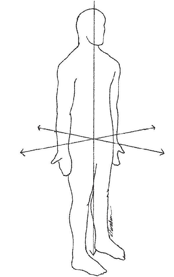
The rotary or translatory displacement of a segment is commonly located in space by using the three-dimensional Cartesian coordinate system, borrowed from mathematics, as a useful frame of reference. The origin of the x-axis, y-axis, and z-axis of the coordinate system is traditionally located at the center of mass (CoM) of the human body, assuming that the body is in anatomic position (standing facing forward, with palms forward) (Fig. 1–5). According to the common system described by Panjabi and White, the x-axis runs side-to-side in the body and is labeled in the body as the coronal axis; the y-axis runs up and down in the body and is labeled in the body as the vertical axis; the z-axis runs front to back in the body and is labeled in the body as the anteroposterior (A-P) axis.3 Motion of a segment can occur either around an axis (rotation) or along an axis (translation). An unconstrained segment can either rotate or translate around each of the three axes, which results in six potential options for motion of that segment.
Figure 1–5 Body in anatomic position showing the x-axis, y-axis, and z-axis of the Cartesian coordinate system (the coronal, vertical, and anteroposterior axes, respectively).
The options for movement of a segment are also referred to as degrees of freedom. A completely unconstrained segment, therefore, always has six degrees of freedom. Segments of the body, of course, are not unconstrained. A segment may appear to be limited to only one degree of freedom (although, as already pointed out, this rarely is strictly true), or all six degrees of freedom may be available to it.
Rotation of a body segment is described not only as occurring around one of three possible axes but also as moving in or parallel to one of three possible cardinal planes. As a segment rotates around a particular axis, the segment also moves in a plane that is both perpendicular to that axis of rotation and parallel to another axis. Rotation of a body segment around the x-axis or coronal axis occurs in the sagittal plane (Fig. 1–6). Sagittal plane motions are most easily visualized as front-to-back motions of a segment (e.g., flexion/extension of the upper extremity at the glenohumeral joint).
Rotation of a body segment around the y-axis or vertical axis occurs in the transverse plane (Fig. 1–7). Transverse plane motions are most easily visualized as motions of a segment parallel to the ground (e.g., medial/lateral rotation of the lower extremity at the hip joint). Transverse plane motions often occur around axes that pass through the length of long bones that are not truly vertically oriented. Consequently, the term longitudinal (or long ) axis is often used instead of “vertical axis.” Rotation of a body segment around the z-axis or A-P axis occurs in the frontal plane (Fig. 1–8). Frontal plane motions are most easily visualized as side-to-side motions of the segment (e.g., abduction/adduction of the upper extremity at the glenohumeral joint).
Rotation and translation of body segments are not limited to motion along or around cardinal axes or within cardinal planes. In fact, cardinal plane motions are the
exception rather than the rule and, although useful, are an oversimplification of human motion. If a motion (whether in or around a cardinal axis or plane) is limited to rotation around a single axis or translatory motion along a single axis, the motion is considered to have one degree of freedom. Much more commonly, a segment moves in three dimensions with two or more degrees of freedom. The following example demonstrates a way in which rotary and translatory motions along or around one or more axes can combine in human movement to produce two- and three-dimensional segmental motion.
Figure 1–6 The sagittal plane.
Figure 1–7 The transverse plane.
Figure 1–8 The frontal plane.
Example 1-1
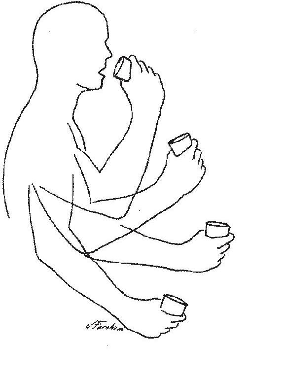
When the forearm-hand segment and a glass (all considered as one rigid segment) are brought to the mouth (Fig. 1–9), rotation of the segment around an axis and translation of that segment through space occur simultaneously. As the forearm-hand segment and glass rotate around a coronal axis at the elbow joint (one degree of freedom), the shoulder joint also rotates to translate the forearm-hand segment forward in space along the forearm-hand segment’s A-P axis (one degree of freedom). By combining the two degrees of freedom, the elbow joint axis (the instantaneous center of rotation for flexion of the forearm-hand segment) does not remain fixed but moves in space; the glass attached to the forearm-hand segment moves through a curvilinear path.
Figure 1–9 The forearm-hand segment rotates around a coronal axis at the elbow joint and along A-P axis (through rotation at the shoulder joint), using two degrees of freedom that result in a moving axis of rotation and produce curvilinear motion of the forearm-hand segment.
Direction of Displacement
Even if displacement of a segment is confined to a single axis, the rotary or translatory motion of a segment around or along that axis can occur in two different directions. For rotary motions, the direction of movement of a segment around an axis can be described as occurring in a clockwise or counterclockwise direction. Clockwise and counterclockwise rotations are generally assigned negative and positive signs, respectively.5 However, these terms are dependent on the perspective of the viewer (viewed from the left side, flexing the forearm is a clockwise movement; if the subject turns around and faces the opposite direction, the same movement is now seen by the viewer as a counterclockwise movement). Anatomic terms describing human movement are independent of viewer perspective and, therefore, more useful clinically. Because there are two directions of rotation (positive and negative) around each of the three cardinal
axes, we can describe three pairs of (or six different) anatomic rotations available to body segments.
Flexion and extension are motions of a segment occurring around the same axis and in the same plane (uniaxial or uniplanar) but in opposite directions. Flexion and extension generally occur in the sagittal plane around a coronal axis, although exceptions exist (e.g., carpometacarpal flexion and extension of the thumb). Anatomically, flexion is the direction of segmental rotation that brings ventral surfaces of adjacent segments closer together, whereas extension is the direction of segmental rotation that brings dorsal surfaces closer together.
Side-bar: Defining flexion and extension by ventral and dorsal surfaces makes use of the true embryologic origin of the words ventral and dorsal, rather than using these terms as synonymous with anterior and posterior, respectively.
Abduction and adduction of a segment occur around the A-P axis and in the frontal plane but in opposite directions (although carpometacarpal abduction and adduction of the thumb again serve as exceptions). Anatomically, abduction brings the segment away from the midline of the body, whereas adduction brings the segment toward the midline of the body. When the moving segment is part of the midline of the body (e.g., the trunk or the head), the rotary movement is commonly termed lateral flexion (to the right or to the left).
Medial (or internal ) rotation and lateral (or external ) rotation are opposite motions of a segment that generally occur around a vertical (or longitudinal) axis in the transverse plane. Anatomically, medial rotation occurs as the segment moves parallel to the ground and toward the midline, whereas lateral rotation occurs opposite to that. When the segment is part of the midline (e.g., the head or trunk), rotation in the transverse plane is simply called rotation to the right or rotation to the left. The exceptions to the general rules for naming motions must be learned on a joint-by-joint basis.
As is true for rotary motions, translatory motions of a segment can occur in one of two directions along any of the three axes. Again by convention, linear displacement of a segment along the x-axis is considered positive when displacement is to the right and negative when it is to the left. Linear displacement of a segment up along the y-axis is considered positive, and such displacement down along the y-axis is negative. Linear displacement of a segment forward (anterior) along the z-axis is positive, and such displacement backward (posterior) is negative.1
Magnitude of Displacement
The magnitude of rotary motion (or angular displacement) of a segment can be given either in degrees (United States [US]units) or in radians(International System of Units [SI units]). If an object rotates through a complete circle, it has moved through 360°, or 6.28 radians. A radian is literally the ratio of an arc to the radius of its circle (Fig. 1–10). One radian is equal to 57.3°; 1°is equal to 0.01745 radian. The magnitude of rotary motion that a body segment moves
through or can move through is known as its range of motion (ROM). The most widely used standardized clinical method of measuring available joint ROM is goniometry, with units given in degrees. Consequently, we typically will use degrees in this text to identify angular displacements (rotary motions). ROM may be measured and stored on computer for analysis by an electrogoniometer or a three-dimensional motion analysis system, but these are available predominantly in research environments. Although we will not be addressing instruments, procedures, technological capabilities, or limitations of these systems, data collected by these sophisticated instrumentation systems are often the basis of research cited through the text.
Translatory motion or displacement of a segment is quantified by the linear distance through which the object or segment is displaced. The units for describing translatory motions are the same as those for length. The SI system’s unit is the meter (or millimeter or centimeter); the corresponding unit in the US system is the foot (or inch). This text will use the SI system but includes a US conversion when this appears to facilitate understanding (1 inch = 2.54 cm). Linear displacements of the entire body are often measured clinically. For example, the 6-minute walk6 (a test of functional status in individuals with cardiorespiratory problems) measures the distance (in feet or meters) someone walks in 6 minutes. Smaller full-body or segment displacements can also be measured by three-dimensional motion analysis systems.
Rate of Displacement
Although the magnitude of displacement is important, the rate of change in position of the segment (the displacement per unit time) is equally important. Displacement per unit time regardless of direction is known as speed, whereas displacement per unit time in a given direction is known as velocity. If the velocity is changing over time, the change in velocity per unit time is acceleration. Linear velocity (velocity of a translating segment) is expressed as meters per second (m/sec) in SI units or feet per second (ft/sec) in US units; the corresponding units for acceleration are meters per second squared (m/sec2) and feet per second
squared (ft/sec2). Angular velocity (velocity of a rotating segment) is expressed as degrees per second (deg/sec), whereas angular acceleration is given as degrees per second squared (deg/sec2).
An electrogoniometer or a three-dimensional motion analysis system allows documentation of the changes in displacement over time. The outputs of such systems are increasingly encountered when summaries of displacement information are presented. A computer-generated time-series plot, such as that in Figure 1–11, graphically portrays not only the angle between two bony segments (or the rotation of one segment in space) at each point in time but also the direction of motion. The steepness of the slope of the graphed line represents the angular velocity. Figure 1–12 plots the variation in linear acceleration of a body segment (or a point on the body segment) over time without regard to changes in joint angle.
Figure 1–11 When a joint’s range of motion is plotted on the y-axis (vertical axis) and time is plotted on the x-axis (horizontal axis), the resulting time-series plot portrays the change in joint position over time. The slope of the plotted line reflects the velocity of the joint change.
Figure 1–12 Movement of a point on a segment can be displayed by plotting the acceleration of the segment (y-axis) over time (x-axis). The slope and trend of the line represent increases or decreases in magnitude of acceleration as the movement continues. (Courtesy of Fetters, L: Boston University, 2003.) 0 10204050 60 70 80 30 Time (100 frames = 1 sec)
Figure 1–10 An angle of 57.3°describes an arc of 1 radian.
INTRODUCTION TO FORCES
Definition of Forces
Kinematic descriptions of human movement permit us to visualize motion but do not give us an understanding of why the motion is occurring. This requires a study of forces. Whether a body or body segment is in motion or at rest depends on the forces exerted on that body. A force, simplistically speaking, is a push or a pull exerted by one object or substance on another. Any time two objects make contact, they will either push on each other or pull on each other with some magnitude of force (although the magnitude may be small enough to be disregarded). The unit for a force (a push or a pull) in the SI system is the newton (N); the unit in the US system is the pound(lb). The concept of a force as a push or pull can readily be used to describe the forces encountered in evaluating human motion
Continuing Exploration 1-1: A Force
Although a force is most simply described as a push or a pull, it is also described as a “theoretical concept” because only its effects (acceleration) can be measured.4 Consequently, a force (F) is described by the acceleration (a) of the object to which the force is applied, with the acceleration being directly proportional to the mass (m) of that object; that is,
force = (mass)(acceleration) or F = (m)(a)
Because mass is measured in kilograms (kg) and acceleration in m/sec2, the unit for force is actually kg-m/sec2 or, more simply, the newton (N). A newton is the force required to accelerate 1 kg at 1 m/sec2 (the pound is correspondingly the amount of force required to accelerate a mass of 1 slug [to be described] at 1 ft/sec2).
External forces are pushes or pulls on the body that arise from sources outside the body. Gravity(g), the attraction of the earth’s mass to another mass, is an external force that under normal conditions constantly affects all objects. The weight(W) of an object is the pull of gravity on the object’s mass with an acceleration of 9.8 m/sec 2 (or 32.2 ft/sec2) in the absence of any resistance:
weight = (mass)(gravity) or W = (m)(g)
Because weight is a force, the appropriate unit is the newton (or pound). However, it is not uncommon to see weight given in kilograms(kg), although the kilogram is more correctly a unit of mass. In the US system, the pound is commonly used to designate mass when it is appropriately a force unit (1 kg = 2.2 lb). The correct unit for mass in the US system is the infrequently used slug (1 slug = 14.59 kg).
Continuing Exploration 1-2: Force and Mass Unit Terminology
Force and mass units are often used incorrectly in the vernacular. The average person using the metric system expects a produce scale to show weight in kilograms, rather than in newtons. In the United States, the average person appropriately thinks of weight in pounds but also considers the pound to be a unit of mass. Because people commonly tend to think of mass in terms of weight (the force of gravity acting on the mass of an object) and because the slug is an unfamiliar unit to most people, the pound is often used to represent the mass of an object in the US system.
One attempt to maintain common usage while clearly differentiating force units from mass units for scientific purposes is to designate lb and kg as mass units and to designate the corresponding force units as lbf (poundforce) and kgf (kilogram-force).3,4 When the kilogram is used as a force unit:
1 kgf = 9.8 N
When the pound is used as a mass unit: 1 pound = 0.031 slugs
These conversions assume an unresisted acceleration of gravity of 9.8 m/sec2 or 32.2 ft/sec2, respectively.
The distinction between a measure of mass and a measure of force is important because mass is a scalar quantity (without action line or direction), whereas the newton and pound are measures of force and have vector characteristics. In this text, we will consistently use the terms newton and pound as force units and the terms kilogram and slug as the corresponding mass units.
Because gravity is the most consistent of the forces encountered by the body, gravity should be the first force to be considered when the potential forces acting on a body segment are identified. However, gravity is only one of an infinite number of external forces that can affect the body and its segments. Examples of other external forces that may exert a push or pull on the human body or its segments are wind (the push of air on the body), water (the push of water on the body), other people (the push or pull of an examiner on John Alexander’s leg), and other objects (the push of floor on the feet, the pull of a weight boot on the leg). A critical point is that the forces on the body or any one segment must come from something that is touching the body or segment. The major exception to this rule is the force of gravity. However, if permitted, the conceit that gravity (the pull of the earth) “contacts” all objects on earth, we can circumvent this exception and make it a standing rule that all forces on a segment must come from something that is contacting that segment (including gravity). The obverse also holds true: that anything that contacts a segment must create a force on that segment, although the magnitude may be small enough to disregard.
ConceptCornerstone 1-1
Primary Rules of Forces
• All forces on a segment must come from something that is contacting that segment.
• Anything that contacts a segment must create a force on that segment (although the magnitude may be small enough to disregard).
• Gravity can be considered to be “touching” all objects.
Internal forces are forces that act on structures of the body and arise from the body’s own structures (i.e., the contact of two structures within the body). A few common examples are the forces produced by the muscles (the pull of the biceps brachii on the radius), the ligaments (the pull of a ligament on a bone), and the bones (the push of one bone on another bone at a joint). Some forces, such as atmospheric pressure (the push of air pressure), work both inside and outside the body, but—in our definition—these are considered external forces because the source is not a body structure.
External forces can either facilitate or restrict movement. Internal forces are most readily recognized as essential for initiation of movement. However, it should be apparent that internal forces also control or counteract movement produced by external forces, as well as counteracting other internal forces. Much of the presentation and discussion in subsequent chapters of this text relate to the interactive role of internal forces, not just in causing movement but also in maintaining the integrity of joint structures against the effects of external forces and other internal forces.
Force Vectors
All forces, regardless of the source or the object acted on, are vector quantities. A force is represented by an arrow (vector) that (1) has its base on the object being acted on (the point of application), (2) has a shaft and arrowhead in the direction of the force being exerted (direction/ orientation), and (3) has a length drawn to represent the amount of force being exerted (magnitude). As we begin to examine force vectors (and at least throughout this chapter), the point of application ( base ) of each vector in each figure will be placed on the segment or object to which the force is applied—which is generally also the object under discussion.
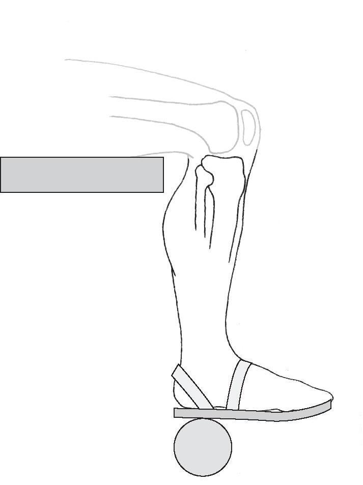
Figure 1–13 shows John Alexander’s leg-foot segment. The weight boot is shaded-in lightly for context but is not really part of the space diagram. Because the weight boot makes contact with the leg-foot segment, the weight boot must exert a force (in this case, a pull) on the segment. The force, called weightboot-on-legfoot (WbLf), is represented by a vector. The point of application is on the leg (closest to where the weight boot exerts its pull); the action line and direction indicate the direction of the pull and the angle of pull in relation to the leg; and the length is drawn to represent the magnitude of the pull. The force weightboot-on-legfoot is an external force because the
weight boot is not part of the body, although it contacts the body. Figure 1–14 shows the force of a muscle (e.g., the brachialis) pulling on the forearm-hand segment. The point of application is at the attachment of the muscle, and the orientation and direction are toward the muscle (pulls are toward the source of the force). The force is called muscle-on-forearmhand (represented by the vector MFh). Although the designation of a force as “external” or “internal” may be useful in some contexts, the rules for drawing (or visualizing) forces are the same for external forces, such as the weight boot, and internal forces, such as the muscle.
The length of a vector is usually drawn proportional to the magnitude of the force according to a given scale. For example, if the scale is specified as 5 mm = 20 N of force, an arrow of 10 mm would represent 40 N of force. The length of a vector, however, does not necessarily need to be drawn to scale (unless a graphic solution is desired) as long as its magnitude is labeled (as is done in Fig. 1–13). Graphically, the action line of any vector can be considered infinitely long; that is, any vector can be extended in either direction (at the base or at the arrowhead) if this is useful in determining the
Figure 1–13 Vector representation of the pull of the weight boot on the leg-foot segment (weightboot-on-legfoot [WbLf]), with a magnitude proportional to the mass and equivalent to the weight of the apparatus.
Figure 1–14 Vector MFh represents the pull of a muscle on the forearm-hand segment.