Pediatric Sonography Fifth Edition
Visit to download the full and correct content document: https://ebookmass.com/product/pediatric-sonography-fifth-edition/
More products digital (pdf, epub, mobi) instant download maybe you interests ...
Pediatric Sonography 4th Edition, (Ebook PDF)
https://ebookmass.com/product/pediatric-sonography-4th-editionebook-pdf/
Rogers’ Textbook of Pediatric Intensive Care Fifth Edition
https://ebookmass.com/product/rogers-textbook-of-pediatricintensive-care-fifth-edition/
Sonography Principles and Instruments 9th Edition –Ebook PDF Version
https://ebookmass.com/product/sonography-principles-andinstruments-9th-edition-ebook-pdf-version/
PharmCards Fifth Edition
https://ebookmass.com/product/pharmcards-fifth-edition/
Stuttering Fifth Edition
https://ebookmass.com/product/stuttering-fifth-edition/
Workbook for Diagnostic Medical Sonography: A Guide to Clinical Practice Obstetrics and Gynecology (Diagnostic Medical Sonography Series) 4th Edition, (Ebook PDF)
https://ebookmass.com/product/workbook-for-diagnostic-medicalsonography-a-guide-to-clinical-practice-obstetrics-andgynecology-diagnostic-medical-sonography-series-4th-editionebook-pdf/
Obstetrics & Gynecology (Diagnostic Medical Sonography Series) 4th Edition, (Ebook PDF)
https://ebookmass.com/product/obstetrics-gynecology-diagnosticmedical-sonography-series-4th-edition-ebook-pdf/
Introduction to Sonography and Patient Care First Edition, (Ebook PDF)
https://ebookmass.com/product/introduction-to-sonography-andpatient-care-first-edition-ebook-pdf/
Abdomen and Superficial Structures (Diagnostic Medical Sonography Series)
https://ebookmass.com/product/abdomen-and-superficial-structuresdiagnostic-medical-sonography-series/
Preface
Since the publication of the fourth edition of Pediatric Sonography in 2010, ultrasound equipment and techniques continue to improve and sonographic imaging of the pediatric patient continues to evolve. We have seen innovations in software and technology, such as elastography, contrast agents, and 3D imaging, which have increased ultrasound utilization and our understanding of the role of ultrasound in the evaluation of disease processes in children. The fact that ultrasound is noninvasive and does not use ionizing radiation makes a compelling case for even more widespread use of this modality in the pediatric population. Furthermore, compared with computed tomography and magnetic resonance imaging, ultrasound is a faster and more cost-effective imaging test for evaluating many pediatric diseases. Given these facts, there is a need for an updated and informative text that can be used as a tool for learningandtrainingaswell asareferencesource.
The goal of the fiftheditionof Pediatric Sonography is againtoprovide a comprehensive text on the clinical applications of sonography in a pediatric population. As in prior editions, I have asked highly knowledgeable and recognized colleagues in sonography to share their experience and insights in their areas of expertise. Virtually all chapters have been extensively revised with new illustrations and images added to reflect important newconceptsandimagingfindings.
This book is intended primarily for practicing radiologists, radiology residents and fellows, and sonographers. Other physicians, such as pediatricians and surgeons, also can derive useful information about the clinical indications and relative value of sonography in the pediatric patient.
As in the first four editions, Chapter 1 discusses practical and clinically relevant physical principles and instrumentation for detecting and displaying the acoustic information. Chapter 2 presents relevant artifacts and pitfalls that are encountered in clinical practice. Because artifacts follow the same physical principles of image production discussed in Chapter 1, they are difficult to avoid, but are important to recognize lest they be mistaken for pathology. In keeping with the goal of presenting complicated material in a clear format, new schematic colorized illustrations demonstrating important physical concepts and artifacts have beenadded.
Chapters 3 to 16 address sonographic findings in specific anatomic areas: head, neck, chest, breast, liver, biliary tract and gallbladder, spleen and peritoneum, gastrointestinal tract, kidneys, retroperitoneum, female and male pelvis, musculoskeletal system, and spine. The organization of each chapter is the same as in prior editions. Each chapter again includes practical ultrasound techniques, normal sonographic anatomy, and abnormal sonographic findings specific for that organ system. However, there has been substantial modification of the text and most images have been replaced with updated and improved examples, reflecting the clinical evolution of ultrasound since the prior edition. There also is additional coverage and illustration of newer technologies, such as elastography and contrast-enhanced ultrasound. The discussion of the role of alternative imaging studies as a complement to sonography in solving common clinical problems has been updated and more multi-modality images are included.
The final chapter, Chapter 17, describes the role of sonography in guiding aspiration, biopsy, and drainage procedures. It has been updated extensively with new diagrams on how to guide needle placement and optimizeoutcomes.
Since the first edition of this text in 1991, the purpose of this book remains the same. A broad spectrum of diseases is discussed, and the key imaging features that enable a specific diagnosis are illustrated. The common clinical findings and underlying pathophysiology are also addressedtoenhanceunderstandingof thediseaseprocesses.
It is my sincere hope that the new edition of Pediatric Sonography will continue to be a cornerstone of pediatric imaging and one that will be
frequently used in daily practice. I have strived to produce a comprehensive text that will be easily readable and offer guidance for radiologists and sonographers on the appropriate use of sonography in imagingpediatricdiseases.
Acknowledgments
Writing a book is a task that requires time and commitment from many people. As editor, it would not have been possible for me to complete this task without the important contributions of manyother individuals,whoI acknowledgebelow.
I offer sincere thanks to Dr. Ellen M. Chung, Department of Radiologic Pathology, Armed Forces Institute of Pathology; Drs. William D. Middleton, Kathryn A. Robinson, James R. Duncan, Sarah E. Connolly, and Eric P. Eutsler of the Mallinckrodt Institute of Radiology; Dr. Oscar M. Navarro of The Hospital for Sick Children; Dr. Prakash Masand of Texas Children’s Hospital; and Dr. Kassa Darge of the Children’s Hospital of Philadelphia. They graciously shared their vast experience and outstanding images to bring depth to their chapters in this edition of Pediatric Sonography.
Mythanks alsogoes tomytalentedsonographers,DeborahReiter,Janet Hurt, Angela Heffernan, Shelly Lopez, and Lindsey Snodgrass at the Mallinckrodt Institute of Radiology. Their skill and dedication to performing high-quality examinations led to the creation of many outstandingimages.
I would also like to express my appreciation to the publishing team at Wolters Kluwer for their assistance and professionalism in the development of Pediatric Sonography, 5th edition. Special thanks to Sharon Zinner, Ashley Fischer, and Lisa Koepenick who guided me through the development of the book. Of course, I need to thank Ryan Shaw who cajoled me into taking up the editorial pen once again. I also express my deepest appreciation to Roxanne Klaas and Bridgett Dougherty, the project managers during the production phase, who transformed the pages into print and prepared the illustrative material.
There could not be a better or more dedicated team with which to work. Without the talents and efforts of this group, this book would not have happened.Thanksfor makingthisbookpossible.
Finally, I wish to thank one more very important person−my husband, Barry A. Siegel, MD, for his support and patience during the many hours that I spent writing and editing this book. His encouragement made the completionof thisbookareality.
Contributors
William D Middleton,KathrynA Robinson,andMarilynJ Siegel
William D Middleton,KathrynA Robinson,andMarilynJ Siegel
Siegel
EllenM ChungandMarilynJ Siegel
MarilynJ SiegelandPrakashM Masand
MarilynJ
Oscar
KassaDargeandMarilynJ.Siegel
MarilynJ
MarilynJ.Siegel
MarilynJ.Siegel
Online Appendix (see eBook)
Please access the eBook bundled with this textto view the online appendix. Access instructions are located on the inside frontcover.
PhysicalPrinciplesand Instrumentation
WILLIAM D.MIDDLETON,KATHRYN A.ROBINSON,AND MARILYN J.SIEGEL
Acoustics
WavelengthandFrequency
PropagationofSound
Instrumentation
Transmitter
Transducer
Receiver
ImageDisplay
ImageStorage
Real-TimeImaging
MechanicalTransducers
Multiple-ElementArray Transducers
TransducerSelection
HarmonicImaging
ExtendedField-of-View Imaging
Real-TimeCompounding
Three-DimensionalUltrasoundImaging
Doppler Sonography
Continuous WaveDoppler
PulsedDoppler
ColorDoppler
PowerDoppler
B Flow
Elastography
Basic Principles ofElastography
Elastography Techniques
ContrastAgents
MicrobubbleImaging
PulseInversionImaging
MechanicalIndex
CHAPTER
Ultrasonography has been a valuable method for displaying normal and abnormal anatomyfor manyyears.Therearemanyreasonswhyit is an especially attractive imaging technique in the pediatric age group. One of the most important features of sonography is its lack of ionizing radiation. One important goal in imaging the pediatric patient is to obtain diagnostic information with the least amount of radiation exposure. Sonography can provide clinically useful information without apparentbiologiceffectsonthepatientortheoperator.
A second appealing aspect of sonography is the real-time nature of the examination. This makes it easier to examine patients who cannot suspend respiration, are uncooperative, or are crying, all common problems among pediatricpatients.Inaddition,thereal-timenatureof theexaminationallows evaluationofrapidlymovingstructures,suchastheheart.
A third advantage of sonography is its multiplanar imaging capability. Newer real-time equipment enables great flexibility in the selection of imaging planes and the ease of altering these planes. This capability is especially helpful in determining the origin of pathologic masses and in analyzing spatial relationships of various structures. These advantages have been expanded even further with the advent of three-dimensional (3D) ultrasound.
Another advantage of sonography in the pediatric age group is its excellent resolution, which is related to the size of the patient and the smaller amounts of body fat. The lack of significant body wall and intraabdominal fat inmost small childrenis a great advantage inthe examination of pediatric patients because fat generally degrades the ultrasonographic image. For a given sonographic unit and type of transducer, higher transmitted frequencies provide better image resolution, but poorer penetration.These conflictingcharacteristics of transducer frequencyforce a compromise in adults in whom lower frequencies must be used to obtain adequate depth of penetration at the expense of image resolution. However, the need for greater depth of penetration is less in children than it is in adults, reflecting the differences in body habitus. Therefore, higher frequency, higher resolution transducers can be used routinely in pediatric examinations.
The ability to perform the examination using portable equipment is another advantage that sonographyhas over other cross-sectional modalities, suchas computedtomography(CT) andmagnetic resonance imaging(MRI).
This is obviously important in evaluating patients who cannot be transported totheradiologydepartment becauseof their underlyingconditionor because oftheirdependenceonmonitoringdevices.
Finally, in the era of medical cost containment, the relative inexpensiveness of ultrasonography, compared with CT or MRI, makes it an attractiveimagingstudyformanyclinical problems.Theissueofcost makes ultrasonography especially appealing in situations in which multiple sequential examinations are necessary or when screening of large patient populationsisdesired.
All of these factors make ultrasonography an extremely valuable tool in the investigation of pediatric disorders. Therefore, any radiologist who performs diagnostic ultrasonography on pediatric patients must have an understanding of the physical principles of this technique and the instrumentation available for detecting and displaying the acoustic information. This information has been described in detail in several comprehensive textbooks, chapters, and review articles (1-6). The following chapter will be limited to the basic physical principles and the instrumentation that are most relevant to the practice of diagnostic ultrasound.
ACOUSTICS
WAVELENGTH AND FREQUENCY
Sound is the result of mechanical energy traveling through matter in the form of a wave with alternating compression and rarefaction of the conducting medium. Human hearing encompasses a range from 20 to 20,000 Hz. Ultrasound differs from audible sound only in its higher frequency. The term ultrasound refers to sound above the audible range (i.e., >20 kHz). Diagnosticsonographygenerallyoperatesatfrequenciesof1to20MHz.
P
ROPAGATION
OF SOUND
Most diagnostic ultrasound examinations use brief bursts of energy that are transmitted into the body where they travel through tissue. In tissue and fluid, sound is propagated along the direction of the particles being displaced. The resistance of the tissues being compressed largely determines the speed at which the sound wave travels. The velocity of propagation is constantforagiventissueandisnotaffectedbythefrequencyorwavelength
of the sound wave. In soft tissues, the assumed average propagation velocity is1540m/s.Fluidandfathaveslightlyslowerpropagationvelocities.
After the sound pulse is generated and transmitted into the body, it can be reflected, refracted, scattered, or absorbed (7). Reflection or backscatter occurswheneverthesoundpulseencountersaninterfacebetweentissuesthat have different acoustic impedances. Acoustic impedance is equal to the tissue density times the speed of sound propagation in that tissue. The amount of soundthat is reflectedat aninterface varies withthe difference in acoustic impedance between the tissues and the angle of incidence of the soundbeam.Thegreater theacousticimpedancemismatchis,thegreater the backscatter or sound reflection. Reflection does not occur in a homogeneous medium that has no interfaces to reflect sound, and consequently, the mediumappearsanechoicorcystic.
Refraction refers to a change in the direction of the sound as it passes from one tissue into another. Refraction occurs when sound encounters an interface between two tissues that transmit sound at different speeds. Because the sound frequency remains constant, the sound wavelength must change to accommodate the difference in the speed of sound in the two tissues. The result of this change in wavelength is a redirection of the sound pulse as it passes through the interface. Refraction is important because it is one of the causes of misregistration of a structure on an ultrasound image. Refraction and its resultant artifacts are discussed in more detail in Chapter 2.
Scattering refers to the redirection of sound in many different directions. This phenomenon occurs when the sound pulse encounters an acoustic interface that is not smooth. Scattering can also occur in solid tissues and organs as a result of the heterogeneity (i.e., multiple small interfaces) of biologicaltissues.
Absorption refers to the loss of sound energy secondary to its conversion to thermal energy. Absorption is greater in soft tissues than in fluid, and it is greater in bone than in soft tissues. Sound absorption is the major cause of acousticshadowing.
The combined effects of reflection, scattering, and absorption are a decrease in the intensity of the sound pulse as it travels through matter. This decrease in intensity is termed attenuation. As a result of attenuation, an acoustic interface in the deeper tissues produces a weaker reflection than an identical interface in the superficial tissues. To compensate for this
degradation in sound intensity, echoes returning from the deeper portions of the image are electronically amplified. This is referred to as distance gain compensation or time gain compensation.
INSTRUMENTATION
The essential components of all scanners are a transmitter to energize the transducer;thetransducer,whichisthesourceofthesoundpulses;areceiver to detect the reflected signals; a display that presents the data for viewing; andastoragemodule.
TRANSMITTER
Thetransmitteractivatesthetransducer,whichcausesit tovibrateandcreate a pulse of sound that can be transmitted into the body. This is done by the application of short high-amplitude voltage pulses. The maximum voltage that may be applied to the transducer and hence, the acoustic output of diagnosticscanners,islimitedbyfederalregulations.
TRANSDUCER
The transducer converts electric energy generated by the transmitter into acoustic pulses, which are transmitted into the patient. It also receives the reflected echoes, converting pressure changes back into electric signals. Becausethecrystal element converts electricenergyintopressurewaves and viceversa,itisreferredtoasa piezoelectric crystal (i.e.,pressureelectric).
Thesoundpulsesusedfordiagnosticsonographyaregeneratedbyceramic crystal elements housed within the ultrasonic transducer. These ceramic crystals deform when the transducer is electrically stimulated, resulting in a band of frequencies. The range of frequencies produced by a given transducer is referred to as the bandwidth. The preferential frequency produced by a transducer is equal to the resonant frequency of the crystal element,which,inturn,isdependentonthethicknessofthecrystal.
The ultrasound pulses produced by the transducer must travel through tissue to generate diagnostic information. The transfer of energy from the transducer to tissue requires the use of a coupling gel. After entering the body, the ultrasound pulses may be propagated, reflected, refracted, scattered, or absorbed as discussed above. The small pressure changes from reflections that return to the transducer distort the crystal element and
stimulate the transducer. This distortion once again generates an electric pulsethatcanthenbeprocessedintoanimage.
RECEIVER
The returning echoes hit the transducer face, producing voltage differences across the piezoelectric crystal. The receiver detects, amplifies, and processes the voltage changes that return to it. The time gain compensation control amplifies the weaker signals from deeper structures, thus compensating for tissue attenuation. The receiver also compresses and remaps the backscattered signals. This changes the brightness of different echolevelsintheimage,whichinturnaffectsimagecontrast.
IMAGE DISPLAY
A- and B-Mode Imaging
Ultrasound images have been displayed in A- and B-mode formats. The A(amplitude) mode format was the earliest one for displaying sound signals returning to the transducer. With this format, the reflections arising from tissue interfaces were displayed in graphic form with time on the horizontal axisandechoamplitudeontheverticalaxis.
The B-(brightness) mode displays the returning sound signal twodimensional (2D) image with higher amplitude echoes appearing brighter than lower amplitude echoes. In both A- and B-mode sonography, the distance of the reflector from the transducer is obtained by converting the timetakenfortheechotoreturntothetransducertoadistance.Thisisbased on the speed of sound in soft tissues, which is equal to 1540 m/s. In general, the range of brightness should be as wide as possible to differentiate small differencesinechointensity.
Intheearly2Dunits,theB-modetransducerwasattachedtoanarticulated arm that wascapableof determiningtheexact locationandorientationof the transducer in space. This allowed the origin of the returning echoes to be localized in two dimensions. Then, by sweeping the transducer across the patient’s body, a series of B-mode lines of information could be added togethertoproducea2Dimage.WithstaticB-modeimaging,it waspossible to view large organs, such as the liver, in one cross-sectional image. The major disadvantage of static B-mode imaging was its lack of real-time
capabilities. Because of this limitation, static articulated-arm B-mode deviceshavenowbeenreplacedbyreal-timeunits.
IMAGE STORAGE
Permanent storage of images for analysis and archiving was originally done in the form of transparencies printed on hard-copy radiographic film. However, computers and digital storage are now used for reviewing images and archiving the sonographic data. Digital imaging and communications in medicine (DICOM) standards are in place to sustain image compatibility between different ultrasound systems and transfer and storage of these images.
REAL-TIMEIMAGING
Real-time imaging permits investigation of anatomy and motion. The effect of motion is achieved when images are displayed at rates of several frames per second. Thus, the information is regarded as being viewed in real time. Severaltransducersareavailableforreal-timeimaging.
MECHANICAL TRANSDUCERS
The earliest and simplest transducer design was the mechanical sector transducer that used a single large piezoelectric element to generate and receive the ultrasound pulses. Beam steering was accomplished by an oscillating or rotating motion of the crystal element itself or by reflection of the sound pulse off an oscillating acoustic mirror. Beam focusing was done byusingdifferent-shapedcrystal elementsorbyattachinganacousticlensto the transducer.The disadvantage of the mechanical sector transducer was the absence of variable focusing. The only way to vary the focus distance was to switch to a completely different transducer. Because of their lack of flexibility, mechanical sector transducers have almost entirely been replaced bymultiple-elementelectronictransducers,commonlycalledarrays.
MULTIPLE-ELEMENT ARRAY TRANSDUCERS
The arraytransducers containgroups of small crystal elements that cansteer and focus the ultrasound beam electronically (Figs. 1-1 and 1-2) (8). The basictypesofarraysarelinearandcurvilinear.
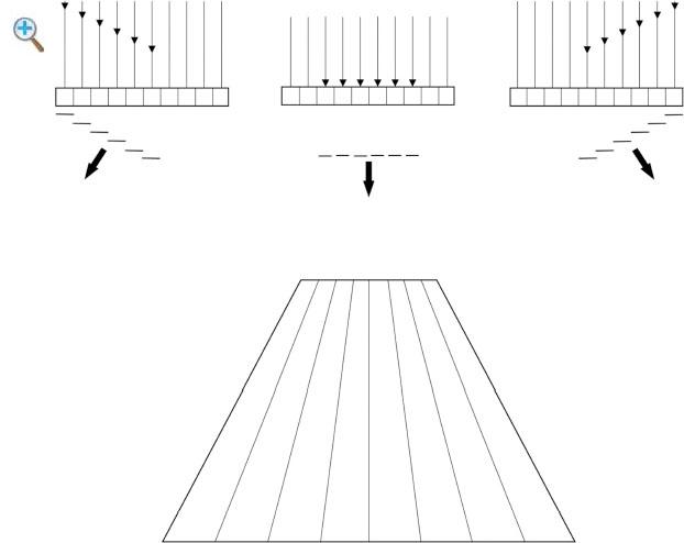
Fig.1-1 Beam steering. By ring the elements on the right side of the array first, a composite pulse is created that is steered to the left By firing all of the elements simultaneously, the composite pulse is steered straight down By firing the left elements first, the pulse is steered to the right. The resulting image has a sector/trapezoidalformat
Fig. 1-2 Focusing of array transducers. By slightly delaying the firing of the center elements, the composite pulse is focused in the far field By increasing the delay in firingofthecentralelements,thecompositepulseis focusedinthenearfield.
Linear Array or Linear Sequenced Array Transducers
Linear arrays activate a group of adjacent elements to generate each pulse. The individual elements of this transducer are arranged in a linear fashion. By firing groups of transducer elements in succession, a series of sound pulses is produced along the face of the transducer and the beam travels sequentially from one side of the transducer to the other (Fig. 1-3). With earlylinear arrays,eachsoundpulse traveledinthe same direction(parallel) and was oriented perpendicular to the transducer surface, resulting in a rectangular image (Figs. 1-3 and 1-4A). Currently, beam steering is commonly used in linear array transducers so that a trapezoidal format is also available (Fig. 1-4B). The major advantages of linear array transducers are high resolution in the near field and a large superficial field of view. Focusing is more uniform in the center and periphery of the image because there is little or no beam steering. The major disadvantages of linear arrays are their limited deep field of view and their large size, which limits their useinareaswhereaccessislimited,suchasinintercostalscanning.
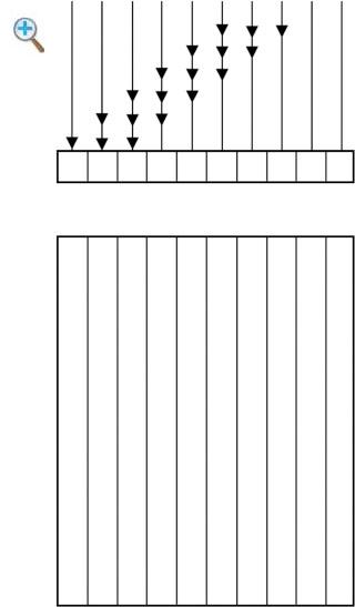
Fig. 1-3 Linear array transducer. In this illustration, there are 10 individual crystal elements Each composite pulse is created by the activation of three adjacent elements The first pulse is created by activation of elements 1 through 3, the second pulse by elements 2 through 4, the third pulse by elements 3 through 5, and soon Theresultingimageformatis rectangular
The disadvantages of the linear array transducers can be minimized by steeringthesoundpulses sothat theydivergefrom eachother.Thetwotypes of probes that diverge sound pulses are the vector and curved linear arrays. Both transducers produce images with sector display formats and large surface field of views. The vector or trapezoidal array transducers can be thought of as small linear arrays that operate only in the trapezoidal format. They produce a sector-like image format with a flat apex (Fig. 1-4C). The curved linear array transducer (also known as the curved array, convex array,
and curvilinear array) (Fig. 1-4D) produces an image with a convex instead ofaflatapex.
Two-DimensionalArrays
The array transducers described above allow for variable depth and electronically controlled focusing of the sound beam in the plane of the image but not inthe directionperpendicular tothe plane of imaging.The net effect of conventional in-plane focusing is on lateral resolution in the plane of imaging. Focusing the beam in the out-of-plane direction (also called the elevation plane) affects the out-of-plane resolution, which is identical to the slice thickness. With the conventional array transducers, the slice thickness isfixedandcannotbevariedbytheoperator(Fig. 1-5).
A solution to variable focusing in the elevation plane is the matrix or 2D array (Fig. 1-6). These probes have crystal elements that are stacked in columns as well as rows. They allow for variable slice thickness that is controlled electronically. They also allowfor 3Dimaging, real-time imaging inorthogonalplanes,andothertimeconsumingtechniques.
Three-DimensionalVolume Probes
As the name suggests,these are dedicated3Dultrasoundtransducers that are capable of volume acquisition. They are bulky in size and house a 2D array transducer in a casing. The 2D array transducer is surrounded by a coupling gelandisdrivenbyamotorasitsweepsthroughapreselectedvolumeangle. Added to the motor is a magnetic sensing device that coordinates the slices of acquisition with their relative position to each other. This allows an acquisition of volume by maintaining the geometric relationships. Maintaining geometric accuracy is important for spatial orientation and measurements when the information is viewed in multiplanar format or as a volume(Fig.1-7).
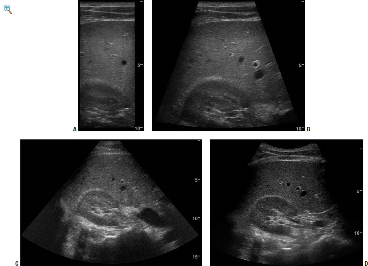
Fig. 1-4 Comparison of standard transducers imaging the liver and kidney. A: Linear array programmed for rectangular imaging In this format, there is excellent resolution throughout the image but a very limited field of view. B: Linear array programmed for sector (trapezoidal) imaging In this format, there is excellent resolution (although slightly less than in the rectangular setting), with a slightly larger field of view. C: Linear array programmed for sector imaging. This format provides the largest field of view with the lowest resolution D: Curved array This provides a compromisewithrelatively highresolutionandarelatively largefieldofview.
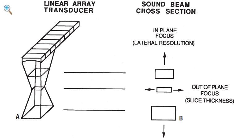
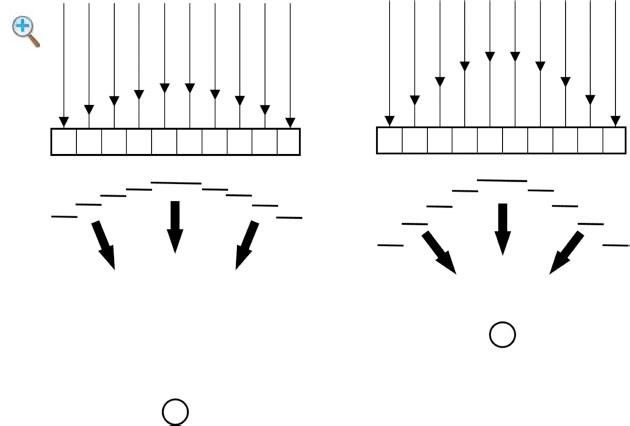
Fig. 1-5 Focusing of standard array transducers. A: Illustration of one individual composite sound pulse generated by firing three adjacent elements of a linear array transducer B: The slice thickness is least in the middle of the pulse due to the curvature of the elements. This is fixed and cannot be controlled by the operator. The in-plane focusing is least in the middle of the pulse due to the electronic focusing.
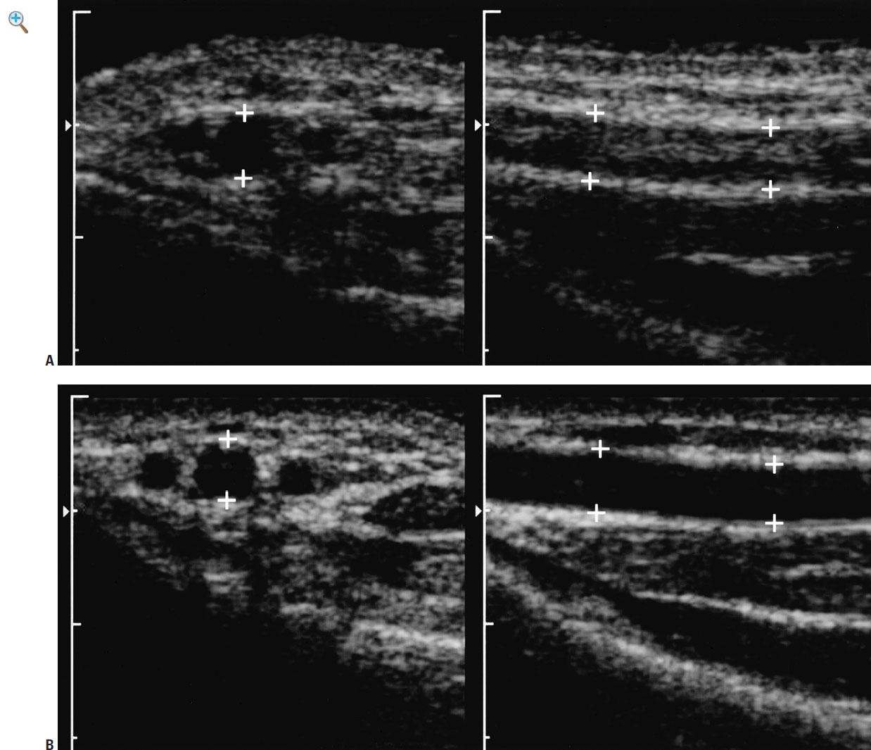
Fig. 1-6 Comparison of conventional array and two-dimensional array. A: Conventional dual scans of the radial artery (cursors) in transverse and longitudinal planes obtained with an operating frequency of 9 MHz. Notice that the artery appears relatively anechoic on the transverse image because in this plane, volume averaging effects are not an issue However, in the longitudinal plane, the slice thickness is greater than the lumen of the vessel producing volume averaging effects with the adjacent soft tissues and echoes within the lumen B: Twodimensional array scans obtained with an operating frequency of 9 MHz. Because theslicethickness canbebetter controlledandreducedwiththis typeof transducer, theluminaldiameter nolonger exceeds thethickness of theslice; this eliminates the volumeaveraginginthelongitudinalplane
TRANSDUCER SELECTION
The selection of a transducer for a given application is dependent on the distance of the object of interest from the transducer. In general, the highest frequency transducer that permits penetration of sound to the target organ should be used. Frequencies of 5.0 or occasionally 3.5 MHz are usually required for evaluation of deeper structures in the abdomen or pelvis. In
obese children and adolescents, frequencies as low as 2.0 MHz may be necessary. For evaluation of superficial structures, 9.0 to 18.0 MHz transducersareusuallyused.
Intracavitary Probes
Recently, transducers have been designed that can be placed within various body lumens. These transducers can be positioned close to the organ of interest, and thus, higher frequencies can be used and higher resolution images can be obtained. The ability to image organs without having to transmit the sound beam through the abdominal wall and intra-abdominal tissues helps to minimize the image-degrading properties of adipose tissue. The overall result is that the images are of much higher quality than those obtained with a standard transabdominal approach. The two most common intraluminal probes are the transrectal and transvaginal transducers (Fig. 18). These are currently used in adults to image the prostate, rectum, perirectalstructures,andfemalepelvicorgans,respectively.Theendovaginal transducerhassomeapplicationsinadolescentgirls(seeChapter13).
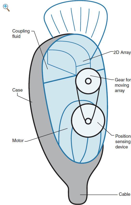
Fig. 1-7 Three-dimensional transducer: Illustration shows the basic design of a volume transducer. Inside the outer casing is a two-dimensional transducer that sweeps through a predefined angle to acquire a volume The magnetic sensor is incorporatedinsidetheprobe’s outercase
Endoscopic Probes
Very small transducers have been added to flexible endoscopes to evaluate pathology in the upper and lower gastrointestinal tracts in adults. In the upper gastrointestinal tract, these transducers can aid in evaluating esophageal and periesophageal abnormalities, gastric wall lesions, and perigastric organs. In the lower gastrointestinal tract, these endoscopic probes have been used to evaluate mucosal and submucosal lesions and pericoloniclesions.
Intra-ArterialProbes
Intra-arterial probes are the most recent addition to the armamentarium of intraluminal sonographic devices. They are used to evaluate a variety of abnormalitiesofthearterialwall.
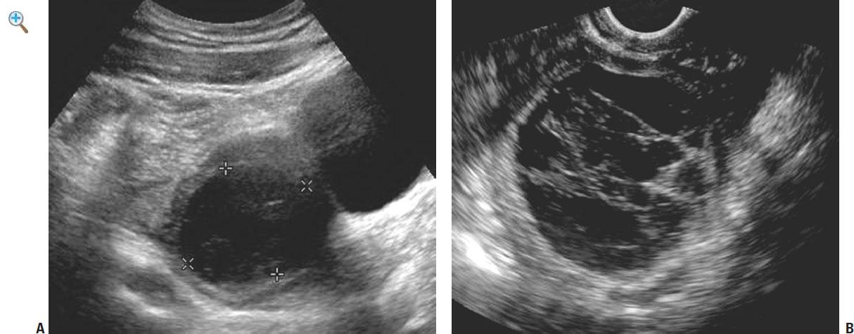
Fig. 1-8 Hemorrhagic ovarian cyst demonstrated with (A) a 35-MHz transducer from a transabdominal approach and (B) a 7.5-MHz transvaginal approach. A nonspecific ovarian cyst is seen on the transabdominal scan The improved resolution on the transvaginal scan demonstrates lacy fibrinous intraluminal membranes typicalofhemorrhagic cysts
HARMONIC IMAGING
Tissue harmonic sonographyis basedonthe principle of nonlinear distortion of the fundamental soundsignal as it travels throughbodytissues.Harmonic wave frequencies are higher integer multiples of the fundamental or transmitted sound frequency. They are produced by propagation of the sound wave within tissues and progressively increase in intensity beforeeventually decreasing because of attenuation. By comparison, conventional sound waves are generated at the surface of the transducer and progressively decrease in intensity as they travel through the body. The same frequency that is transmitted into the patient is subsequently received to create the sonographic image.Althoughmanyharmonic frequencies are generatedwith propagation of the initial wave, the current technology uses only the second harmonic,whichistwicethetransmittedfrequency,forharmonicimaging.A filter is used to remove the original transmitted frequency so that only the returning high-frequency harmonic signal is processed to produce an image (9-15).
Experimental studies have shown that harmonic beams are narrower than the transmitted beam and have fewer side-lobe artifacts. Side-lobe artifacts are artifactual echoes that are especially noticeable in fluid-filled structures. The reduced width of the beam improves lateral resolution and the reduction in artifacts improves the signal-to-noise ratio. The increased lateral resolution improves the resolution of small objects. The higher signal-tonoise ratio results in images where the tissues appear brighter and cavities appear darker (Fig. 1-9) (9,12,14). Furthermore, because harmonic signals are produced after the beam enters the tissues of the body, the defocusing effect of body wall fat are minimized. Results of clinical series have shown that harmonic imaging can improve resolution of lesions containing calcification (i.e., ureteral stones), fat, and air (9,12). Harmonic imaging is particularly valuable in improving lesion visibility in obese patients, but it generallyproducesimprovedimagequalityinmostscanningsituations.
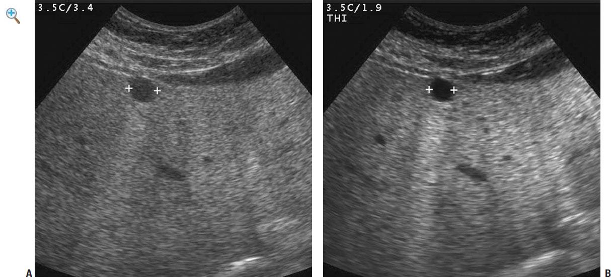
Fig. 1-9 Harmonic ultrasound. A: Conventional scan of the liver obtained at a fundamental frequency of 34 MHz A lesion is seen (cursors), but diffuse internal echoes makeitimpossibletodiagnoseacystwithconfidence.B: Harmonic scanof the same lesion obtained with a transmittal frequency of 19 MHz and a harmonic signal of 38 MHz The lesion now appears anechoic and the diagnosis of a simple cystcanbemadewithconfidence.
Harmonic imaging also appears to have several theoretical advantages over conventional contrast-enhanced Doppler sonography in the evaluation of tissue blood flow. By receiving the second harmonic frequency, backscatter from contrast agents is much greater than that from tissue. In addition, flash artifacts are eliminated, shadowing artifacts are minimized, and both spatial and temporal resolutions are improved (16-20). Experimental studies have suggested that contrast-enhanced harmonic imaging may help in detection of early acute urinary obstruction and focal renal perfusion defects, such as those associated with pyelonephritis or infarction(20,21).
EXTENDED FIELD-OF-VIEW IMAGING
Compared with other imaging techniques such as CT and MRI, sonography has the advantage of being less expensive, having real-time capabilities, and being non-invasive. On the other hand, anatomic spatial relationships and lesion size are readily appreciated using techniques with large field of views such as CT or MRI. One disadvantage of ultrasound is its limited field of view, which is especially true with the high-resolution linear array transducer, which has a limited field of view because of the small footprint
of the transducer. Thus, anatomic spatial relationships and sizes in ultrasound must often be synthesized in the mind of the sonologist from multiplereal-timeimages that displayonlyportions of therelevant anatomy. It is often difficult to illustrate pertinent findings and relevant anatomy to clinicianswhenusinghigh-frequencyprobes.
Image registration based position sensing techniques can now extend the sonographic field of view. The extended field-of-view technology generates panoramicimageswithnolossinresolutionandwithout anexternal position sensor(Fig. 1-10).The technologyuses anechotrackingbasedtechnique for estimating probe motion that is applicable to all conventional real-time transducers (22,23). Geometric measurement accuracy up to a 60-cm scan distance has been verified in phantoms (24). Small-scale tissue motion and off-planeprobemotiondoesnotcompromiseaccuracy.

Fig. 1-10 Panoramic (extended field-of-view) imaging of chest wall lymphoma A: Conventional longitudinal linear array view of the posterior chest shows a solid, hypoechoic mass (M) infiltrating around the ribs (R) and extending to the pleura (arrow) B: Panoramic view shows the full extent of the mass and highlights the rib involvement by comparing with uninvolved ribs. It also allows for better visualization ofthemass effectthelesionexerts onthepleura(arrows)
REAL-TIMECOMPOUNDING
Withconventional linear arrayimaging,thesoundbeamsaresteeredstraight down. With real-time compounding, the sound is steered at multiple angles, as well as straight down, and the resulting frames are averaged together. Weak reflectors, such as fluid, will produce a minimal signal from all