Medical Imaging Centre, Semmelweis University, Budapest, Hungary
Koen Nieman
Stanford University School of Medicine, Division of Cardiovascular Medicine and Department of Radiology, Stanford, CA, USA
Gianluca Pontone
Department of Perioperative Cardiology and Cardiovascular Imaging, Centro Cardiologico Monzino IRCCS, Milan, Italy
Francesca Pugliese
Queen Mary University of London and St Bartholomew’s Hospital, London, UK
Great Clarendon Street, Oxford, OX2 6DP, United Kingdom
Oxford University Press is a department of the University of Oxford. It furthers the University’s objective of excellence in research, scholarship, and education by publishing worldwide. Oxford is a registered trade mark of Oxford University Press in the UK and in certain other countries
The moral rights of the authors have been asserted
First Edition published in 2023
Impression:
All rights reserved. No part of this publication may be reproduced, stored in a retrieval system, or transmitted, in any form or by any means, without the prior permission in writing of Oxford University Press, or as expressly permitted by law, by licence or under terms agreed with the appropriate reprographics rights organization. Enquiries concerning reproduction outside the scope of the above should be sent to the Rights Department, Oxford University Press, at the address above
You must not circulate this work in any other form and you must impose this same condition on any acquirer
Published in the United States of America by Oxford University Press 98 Madison Avenue, New York, NY 006, United States of America
British Library Cataloguing in Publication Data
Data available
Library of Congress Control Number: 202294528
ISBN 978– 0–9–288445– 9
DOI: 0.093/med/978092884459.00.000
Printed in Great Britain by Bell & Bain Ltd., Glasgow
Oxford University Press makes no representation, express or implied, that the drug dosages in this book are correct. Readers must therefore always check the product information and clinical procedures with the most up- to- date published product information and data sheets provided by the manufacturers and the most recent codes of conduct and safety regulations. The authors and the publishers do not accept responsibility or legal liability for any errors in the text or for the misuse or misapplication of material in this work. Except where otherwise stated, drug dosages and recommendations are for the non- pregnant adult who is not breast- feeding
Links to third party websites are provided by Oxford in good faith and for information only. Oxford disclaims any responsibility for the materials contained in any third party website referenced in this work.
Preface
Since the introduction of computed tomography (CT) in 969 by Sir Godfrey Hounsfield, this technology has evolved at a breathtaking pace to become a cornerstone of non- invasive imaging in clinical practice. A giant leap was realized with the introduction of multislice CT scanners with short rotation times and the necessary spatial and temporal resolution to resolve the smallest, moving parts of cardiac anatomy: the coronary arteries. Supported by further technological refinements, clinical trial evidence, and guideline recommendations, cardiac CT, and, foremost, coronary CT angiography (CCTA), has been embraced as an indispensable noninvasive cardiac imaging modality and an important first- line test for coronary artery disease. Recently, the potential of cardiac CT has become evident in the diagnosis and guidance of treatment in a variety of other cardiac pathologies beyond coronary artery disease, including valvular disease, atrial fibrillation and other arrhythmias, endocarditis, cardiac masses, cardiomyopathies, and others.
On these grounds, the European Association of Cardiovascular Imaging (EACVI) has declared that one of their foremost priorities is to facilitate education and training in cardiovascular CT through teaching courses, congresses, and a structured certification programme (see Chapter 4.). This handbook represents an important step towards the dissemination of skills and knowledge in cardiovascular CT. It is conceived as a concise and practical companion, to benefit students, trainees, or advanced users (cardiologists, radiologists, cardiac surgeons, and technicians) in their everyday practice. Four broad sections cover the technical aspects and physical background, coronary indications (e.g. CCTA, atherosclerosis imaging, stents and bypasses, and functional CT imaging), non- coronary indications (CT for valve disease, infective endocarditis, CT of the left atrium, congenital heart disease, cardiac masses, extracardiac findings, etc.), and, finally, training and competence in cardiac CT. The handbook features short chapters, enriched with plenty of illustrations, tables, and condensed summaries, which facilitate rapid and intuitive access. We believe that among the many textbooks available, our handbook fills an important gap, and hope that it will find its way into the pockets of many practitioners’ lab coats.
The recent COVID-9 pandemic has placed tremendous strain on healthcare systems worldwide. The disease has not only caused a large toll of casualties, but also exhausted medical resources to an unprecedented level. CT has become a central imaging tool in patients with COVID throughout the entire course of their disease and associated conditions. High- resolution CT of the pulmonary parenchyma can visualize the typical ground- glass and reticular opacities of COVID pneumonia and allow for rapid diagnosis and risk stratification. In the least ill patients, expedited discharge from the overcrowded Emergency Room is facilitated by CT. Beyond pulmonary involvement, a vast number of complications can affect the cardiovascular system and can be readily assessed with CT, including thromboembolic complications and pericardial and pleural effusions. Patients with acute chest pain and
vi inconclusive electrocardiograms can be rapidly and safely investigated with cardiac CT, thus avoiding invasive coronary angiography, which poses a higher infection risk for medical personnel. In addition, using cardiac CT instead of transoesophageal echocardiography in ruling out left atrial appendage thrombus before atrial fibrillation ablation proved to be invaluable during the pandemic. Indeed, the COVID-9 pandemic has reinforced interest in CT as a robust, rapid, and reliable imaging technology, and has emphasized the need for appropriate education and training. We sincerely hope that this handbook will contribute to improving the skills and knowledge of the large number of healthcare providers fighting every day at the forefront of the global pandemic.
Oliver Gaemperli Pal Maurovich- Horvat Koen Nieman Gianluca Pontone Francesca Pugliese
3. Non- coronary artery disease
4. Training and competence in cardiac CT
4. European Association of Cardiovascular Imaging certification standards in cardiac CT
Department of Cardiology, Copenhagen University Hospital – Amager and Hvidovre, Denmark; Department of Clinical Medicine, University of Copenhagen, Denmark
Chapter .3
Mihály Károlyi
Institute of Diagnostic and Interventional Radiology, University Hospital Zurich, Zurich, Switzerland
Chapters .4 and .9
Jamal Khan
Department of Cardiology, University Hospitals of Coventry & Warwickshire NHS Trust, Coventry, UK
Chapter .6
Martina de Knegt
Barts Heart Centre, Centre for Advanced Cardiovascular Imaging, William Harvey Research Institute, Queen Mary University of London, London, UK
Chapter .3
Márton Kolossváry
Cardiovascular Imaging Research Center, Massachusetts General Hospital, Harvard Medical School, Boston, MA, USA
Chapters 2.6 and 3.6
Bibi Martens
Cardiovascular Research Institute
Maastricht (CARIM), Maastricht University, and Department of Radiology and Nuclear Medicine, Maastricht University Medical Center, Maastricht, the Netherlands
Chapter .0
Mohamed Marwan
Cardiology Department, University Hospital Erlangen, Erlangen, Germany
Chapter .9
Domenico Mastrodicasa
Stanford University School of Medicine, Department of Radiology, Center for Academic Medicine, Palo Alto, CA, USA
Chapter 2.4
Pál Maurovich- Horvat
Medical Imaging Centre, Semmelweis University, Budapest, Hungary
Chapter 2.2
Michael Messerli
Department of Nuclear Medicine, University Hospital Zurich/University of Zurich, Zurich, Switzerland
Chapters 3.9 and 3.5
Casper Mihl
Cardiovascular Research Institute
Maastricht (CARIM), Maastricht University, and Department of Radiology and Nuclear Medicine, Maastricht University Medical Center, Maastricht, the Netherlands
Chapter .0
Sarah Moharem- Elgamal
Liverpool Heart and Chest Hospital, Liverpool, UK; National Heart Institute, Giza, Egypt
Chapters .6, ., and 3.3
Giuseppe Muscogiuri
School of Medicine and Surgery, University of Milano- Bicocca, Milan, Italy; Department of Radiology, IRCCS
Istituto Auxologico Italiano, San Luca Hospital, Milan, Italy
Chapters 3.2 and 3.3
Koen Nieman
Stanford University School of Medicine, Division of Cardiovascular Medicine and Department of Radiology, Stanford, CA, USA
Chapters 2.5, 2.7, and 2.8
Gianluca Pontone
Department of Perioperative Cardiology and Cardiovascular Imaging, Centro Cardiologico Monzino IRCCS, Milan, Italy
Chapter 2.5
Francesca Pugliese
Queen Mary University of London and St Bartholomew’s Hospital, London, UK
Chapters ., .5, .6, and .7
Ronak Rajani
Guy’s and St Thomas’ NHS Foundation Trust and King’s College London, London, UK
Chapter .4
Ian Rogers
Stanford University School of Medicine, Division of Cardiovascular Medicine, Department of Medicine, Stanford, CA, USA
Chapter 2.8
Alexia Rossi
Department of Nuclear Medicine, University Hospital Zurich; and Center for Molecular Cardiology, University of Zurich, Zurich, Switzerland
Chapter .3
Marcel van Straten
Erasmus Medical Center, University Medical Center, Department of Radiology and Nuclear Medicine, Rotterdam, the Netherlands
Chapter .
Bálint Szilveszter
Semmelweis University Heart and Vascular Center, Budapest, Hungary
Chapter 2.2
Richard A.P. Takx
Amsterdam University Medical Center, Department of Radiology and Nuclear Medicine, Amsterdam, the Netherlands
Chapters 2.2 and 3.
Sebastian Vandermolen
Barts Heart Centre, London, UK
Chapter .
Martin Willemink
Stanford University School of Medicine, Department of Radiology, Stanford, CA, USA
Chapter 2.
Abbreviations
AC alternating current
ACHD adult congenital heart disease
ACS acute coronary syndrome
AF atrial fibrillation
AHA American Heart Association
AI artificial intelligence
ALARA as low as reasonably achievable
ALCAPA anomalous LMCA from the pulmonary artery
AR aortic regurgitation
ARCAPA anomalous RCA from the pulmonary artery
AS aortic stenosis
ASD atrial septal defect
BAV bicuspid aortic valve
BMI body mass index
bpm beats per minute
BSA body surface area
CA catheter ablation
CAA coronary artery anomaly
CABG coronary artery bypass grafting
CAC- DRS Coronary Artery Calcium Data and Reporting System
CAD coronary artery disease
CAD- RADS Coronary Artery Disease – Reporting and Data System
CAV cardiac allograft vasculopathy
CCT cardiac CT
CCTA coronary CT angiography
CDRIE cardiac device- related infective endocarditis
CIN contrast- induced nephropathy
CM contrast media
CMR cardiac magnetic resonance
cMPR curved multiplanar reconstruction
CS coronary sinus
Abbreviations
xvi
CTA CT angiography
DC direct current
EACVI European Association of Cardiovascular Imaging
ECF extracardiac finding
ECG electrocardiogram
ECV extracellular volume
ED Emergency Department
EDV end diastole
EF ejection fraction
ESC European Society of Cardiology
ESV end systole
FBP filtered back projection
FFR fractional flow reserve
FoV field of view
GCV great cardiac vein
GFR glomerular filtration rate
HR heart rate
HTX heart transplantation
HU Hounsfield unit
ICA invasive coronary angiography
ICRP International Commission on Radiological Protection
IDR iodine delivery rate
IE infective endocarditis
IMA internal mammary artery
IMH intramural haematoma
IV intravenous(ly)
IVC inferior vena cava
keV kiloelectron volts
kV kilovoltage
LAA left atrial appendage
LAD left anterior descending artery
LCA left coronary artery
LCX left circumflex artery
LMA left main artery
LMCA left main coronary artery
LNT linear no-threshold
lp/cm line- pairs per cm
LR likelihood ratio
LV left ventricle
LVOT left ventricle outflow tract
mA milliAmperes
MACE major adverse cardiac events
MBF myocardial blood flow
MCQ multiple- choice question
MI myocardial infarction
MIP maximum intensity reconstruction
ML machine learning
MPI myocardial perfusion imaging
MPR multiplanar reconstruction
MR mitral regurgitation
mSv millisievert
MRI magnetic resonance imaging
MV mitral valve
NICE National Institute for Health and Care Excellence
NSTE- ACS non- ST elevation acute coronary syndrome
PA pulmonary artery
PAU penetrating atherosclerotic ulcer
PCI percutaneous coronary intervention
PDA posterior descending artery
PTP pretest probability
PV pulmonary vein
PVE prosthetic valve endocarditis
RCA right coronary artery
RCT randomized clinical/controlled trial
RV right ventricle
RVEF right ventricle ejection fraction
RVOT right ventricular outflow tract
SAVR surgical aortic valve replacement
SCCT Society of Cardiovascular Computed Tomography
SPECT single photon emission CT
SVC superior vena cava
TAVI transcatheter aortic valve implantation
TEVAR thoracic endovascular aortic repair
TMVR transcatheter mitral valve replacement
Abbreviations
xviii
transoesophageal echocardiography
TSH thyroid stimulating hormone
2D two- dimensional
ViMAC valve- in- mitral annular calcification
ViR valve- in- ring
VSD ventricular septal defect
Chapter .
Key hardware components of a cardiac- enabled CT scanner
Sebastian Vandermolen, Marcel van Straten, and Francesca Pugliese
Teaching points
• Contemporary CT scanners comprise a rotating gantry onto which the X- ray tube(s) and the detector array(s) are housed.
• Collimators determine the shape of the emitted X- ray beam to maximize image quality and minimize radiation exposure to patients.
• Detectors receive and transform the signal necessary to reconstruct CT images.
• The term ‘multidetector’ or ‘multislice’ CT refers to the ability to image multiple sections of the patient’s anatomy along the z- axis during one gantry rotation.
• ‘Dual- source’ CT contains two X- ray sources coupled with two detector arrays mounted at an (approximately) 90- degree angle. Dualsource CT allows doubling of the temporal resolution compared to a single- source system with the same gantry rotation time.
• A motorized scanner table, the electrocardiogram (ECG) synchronization system, and power injection are further key requirements to deliver cardiac CT in clinical practice.
Gantry
The gantry is the ring- shaped structure that houses the X- ray tube and the detector array.
• In contemporary scanners, the gantry can rotate continuously thanks to (contactless) slip-ring technology. Slip-ring technology allows fast transfer of power and data to and from the gantry without the need of power cables. Power cables would require unwinding every few turns, which would prevent continuous rotation and require reversal of gantry rotation. Cables can be replaced by brush technology that is in permanent electrical contact with the gantry and allows continuous rotation.
• The switch- mode power supply allows construction of a small and light but efficient power supply that can be housed in the gantry while generating very
high voltages with limited heat production. In general, this works by converting alternating current (AC) to direct current (DC) using a switch circuit. The DC current is reconverted to AC at a higher frequency.
• The gantry rotation time is a key determinant of temporal resolution, a paramount scanner requirement for cardiac CT (discussed in Chapter .2). In a single- source (one X- ray tube) scanner, approximately half a revolution is needed for the acquisition of data required to reconstruct one image (half- scan algorithm). A single- source CT scanner with a rotation time of 300 ms can sample data for one image in 50 ms, which is the temporal resolution of this scanner.
X-ray tube
The X- ray tube is the component where X- ray generation occurs (Figure ..).
• A tungsten filament is heated by current and emits electrons (thermionic emission).
Figure .. Simplified structure of an X- ray tube.
• By applying a potential difference (kilovoltage, kV) between the cathode and the anode, the electrons are accelerated towards a positively charged anode.
• The resulting flow of electrons represents the tube current, measured in milliAmperes (mA).
• The electrons gain energy proportional to the voltage applied (kV).
• The electron beam hits the focal spot of the anode. About 4% of the energy of the beam leads to the generation of X- ray photons; the rest is dissipated as heat.
• The emitted X- ray beam displays a range of different energies (polychromatic X- ray spectrum), from a few kiloelectron volts (keV) to the nominal value of the applied tube voltage (discussed further in Chapter .3, Figure .3.).
• If the applied voltage is 00 kV, the average energy of the X- ray beam is 50– 60 keV.
• Lower- energy X- rays are removed from the X- ray beam by the tube housing and by filtration: this is because energies at the lower end of the spectrum would otherwise be absorbed by tissue before reaching the detector and would contribute to patient dose but not to image formation.
• The X- ray tube voltage determines the average energy of the X- ray beam; the X- ray tube current determines how many X- ray photons the X- ray beam is comprised of, without affecting their energy.
• The intensity of the X- ray beam decreases with the inverse of the distance from the source squared.
• When traversing tissue, the intensity of the X- ray beam decreases as X- ray photons interact with atoms (Chapter .3). The transmitted intensity depends on the initial intensity, the thickness of the tissue/material traversed, and their linear attenuation coefficient. The latter depends not only on the atomic number of the tissue/material, but also on photon energy and is generally higher at lower energy.
Collimators
The term ‘collimation’ refers to the process of restricting or confining a beam of particles.
• Beam collimators are used to shape the X- ray beam emitted, reduce unnecessary radiation, and maximize image quality.
• Pre- patient collimators determine the width of the beam (fixed and adjustable collimators).
• The heart is centrally located in the patient’s axial cross section; image quality can be reduced in peripheral regions that are of limited interest. Additional shaped filters in cardiac CT may reduce radiation exposure for peripheral organs and tissues.
Detectors
The detection of X- rays constitutes the key ‘signal’ to form projection images needed to reconstruct CT images.
• Current CT detector technology is based on solid- state rare earth ceramics.
• Incident X- rays are absorbed with release of light photons.
• Light photons are detected by photodiodes and converted into an electrical signal.
Detector terminology and configuration
The term ‘multidetector’ or ‘multislice’ CT refers to the ability to image multiple sections of the patient’s anatomy along the z- axis during one gantry rotation (see also Chapter .2 and Figure .2.2).
• Detector element size is the width of the detector row in the x– y plane and is related to in- plane spatial resolution.
• Detector row width is the width of the detector row in the z- axis, determining the minimum slice thickness and the through- plane (longitudinal) spatial resolution (fixed hardware characteristics of the detector array).
• In the past, detector configurations varied across manufacturers and scanner models. Modern cardiac CT systems feature isotropic detector configuration, meaning that detector rows have constant width.
• Detector rows can be combined to increase slice thickness to a multiple of the detector width. The decision to do so can be made at the time of scanning to increase signal and reduce dose, at the expense of though- plane spatial resolution. This approach is not typically used in cardiac CT, where the highest spatial resolution is mandatory.
• It is possible to increase slice thickness post- scanning, by reconstructing thicker slices to reduce image noise (e.g. very large patients).
Dual-source CT
While single- source CT systems contain one X- ray tube and one detector array, ‘dual- source’ CT contains two X- ray sources coupled with two detector arrays mounted at an (approximately) 90- degree angle (Figure ..2).
• Dual- source CT is a scanner design solution that allows the doubling of temporal resolution without decreasing gantry rotation time.
• The two-tube detector systems simultaneously generate X- rays and acquire data so that a 90- degree gantry revolution (instead of 80- degree) is sufficient to acquire data for the reconstruction of one image.
Dual- energy CT
Figure ..2 The simplified geometries of single- and dual- source CT. A, A’: X- ray tube(s); B, B’: detector array(s).
• Dual-source CT allows dual- energy applications. In dual-source dual-energy CT, different X-ray tube voltages are applied to each of the X-ray tubes. This is done to exploit the differential ability of tissues (with different atomic numbers) to attenuate X-rays of variable energy, with the goal of differentiating tissues on the images.
• Different approaches to dual- energy (or multiple- energy) CT do not require dual- source CT. Dual- layer detectors comprise two layers made of different scintillating materials that selectively detect X- rays of different energy. Ultrafast kV switching involves rapid changes in X- ray tube potential with generation of Xray beams of different energy.
• Dual- energy CT is not widely applied in cardiac imaging. Potential applications include subtraction of coronary artery calcium (Chapter 2.), plaque imaging (Chapter 2.6), and characterization of myocardial enhancement such as in perfusion and scar imaging (Chapter 2.5).
Other hardware components
• The scanner table is the motorized platform to move the patient in and out of the gantry. The longitudinal coverage of the scanner is often smaller than the region of interest. Multiple acquisitions can be made at different table positions
(sequential scanning). The table can move continuously through the gantry during scanning (helical or spiral scanning).
• Electrocardiogram (ECG) recording capability allow for the synchronization of image acquisition and reconstruction with specific phases of cardiac cycle. Four ECG electrodes are usually required
• A power injector is required to allow rapid injection of contrast agent to depict cardiac chambers and coronary tree. A power injector consists of (i) injector ‘head’— allows insertion of syringes of contrast; (ii) piston plungers— push the contrast from syringe into patient; and (iii) pressure tubing— connects the syringe to the patient’s intravenous access.
Further reading
Goldman LW. Principles of CT and CT technology. J Nucl Med Technol 2007; 35: 5–28.
Stirrup J, Bull R, Williams M, Nicol E (eds). Cardiovascular Computed Tomography, 2nd edn. New York: Oxford Medical Publications, 2020.
Technical requirements for cardiac CT scanning
Ulrike Haberland and Thomas Allmendinger
Teaching points
• High- quality cardiac CT imaging depends on motion-free images. In half- scan mode, temporal resolution can be defined as the time required to acquire data to reconstruct one CT image. Therefore, temporal resolution depends not only on the scanner’s rotation time, but also on the number of X- ray sources and the availability of multisegment reconstruction.
• Some manufacturers have introduced coronary motion correction algorithms to reduce image motion blur.
• The scanner’s detector coverage influences the number of cardiac cycles needed to complete the scan range and depends on physical collimation, number of slices, and detector element size (slice width). The scan pitch also influences through- plane (z- axis) coverage in the spiral scanning mode. Wide area detectors aim to cover the heart in a single cardiac cycle without table movement.
• The typical size of coronary artery lesions is in the sub- millimetre range. Spatial resolution is the ability to discern two objects as separate from one another. In- plane and through- plane (isotropic) spatial resolution depends on focal spot size, individual detector element size, number of detector channels, number of projections/views, system geometry, and reconstruction filter/kernel.
• Coronary artery CT angiography is based on high iodine contrast imaging, which can be optimized by adjusting the X- ray tube kilovoltage (kV) to influence iodine enhancement and the tube current (mAs) to mitigate noise.
Resting phases
Given that the heart moves continuously, the primary aim of a cardiac CT scan is to ‘image during the resting phase(s)’.
Figure .2. The resting phases in patients with a heart rate (HR) of 60 beats/min (bpm; upper panel) and 85 bpm (lower panel). Of note, there is significant shortening of the diastolic resting phase (blue) with increasing HR, while the systolic resting phase (green) remains fairly stable.
• Diastole has a typical resting phase duration of approximately 200 ms at a heart rate (HR) of 60 bpm, which rapidly decreases towards higher HRs.
• Systole also has a resting phase at its end but is significantly shorter at about 20 ms; however, to some extent, it is relatively constant over a wider HR range (Figure .2.).
• These physiological findings build the basis for the established strategies of coronary CT angiography (CCTA) imaging: end- diastolic imaging for low-tointermediate HRs; and end- systolic imaging for high HRs (see also Chapters .5 and .9, and Figure .5.). The ill- defined range in between often requires images from both diastolic and systolic phases in order to achieve diagnostic image quality.
Temporal resolution
Owing to the short duration of cardiac ‘rest phases’, optimizing CT acquisition and reconstruction towards speed to ‘freeze motion’ is essential. Temporal resolution is the time required to acquire data to reconstruct one CT image. CT images consist of individual X- ray data projections recorded during the rotation of the CT system. The minimum amount of parallel projection data required for a single CT image in a half- scan, filtered back projection- based image reconstruction is 80 degrees (see also Chapter .). In single- source CT, data corresponding to a time span of half gantry rotation contribute to a single cardiac image; hence, the temporal resolution is defined as ½ times the rotation time. Any movement during this time leads to blurred images.
Optimization of the temporal resolution can be achieved by:
• Faster gantry rotation times, which are limited by increasing G- force experienced by the rotating components, data transmission rate increase, and tube power.
• Using CT systems with two tubes (dual- source technology). The required 80 degrees of data consist of two separate, simultaneously recorded data fragments of approximately 90 degrees (see Chapter .). The in- plane temporal resolution is decreased to around /4 of the rotation time.
• Multisegment reconstruction. This approach involves acquisition of data over several cardiac cycles at the same table position, with combination of the data in the reconstruction process. Typical numbers of segments are 2, 3, 4, and 5 (vendor- specific; Figure .2.2). Ideally, this results in a temporal resolution of /4 (two- segment), /6 (three- segment), /8 (four- segment), or /0 (five- segment) of the rotation time. This can only be achieved for specific HRs, which makes the effectiveness of this approach difficult to predict. Segmented reconstructions require stable HRs and can suffer from blurring due to beat-to- beat variability. The amount of recorded data must be increased, which usually leads to a higher radiation dose.
• Intelligent coronary wall motion correction algorithms track the vessel path and velocity to compensate adaptively for residual image motion (blur) on a pervessel and segment basis.
Figure .2.2 The principle of single- segment (left) and multisegment reconstruction (right; two segments in this case). Image data at the same table position are acquired over several cardiac cycles and combined in the reconstruction process. Segmented reconstructions require stable heart rates (upper right panel) and can suffer from heart rate variability (lower right panel).
Single-segment reconstruction
Multisegment reconstruction
• In wide- area detector scanners, if the entire cardiac scan range can be covered in one gantry rotation, the scanner table remains stationary. All images in the scan range will be simultaneously acquired during one cardiac cycle.
Detector coverage
The typical scan length of CCTA or calcium scoring examinations is around 4 cm. Notable exceptions are CCTA bypass examinations with longer scan ranges of around 6–22 cm.
• Ideally, the required scan length is covered in a single scan of a single cardiac cycle.
• In all other cases, the acquisition is spread over multiple cardiac cycles, which results in a block-wise combination of the reconstructed images based on data from multiple cardiac cycles, covering the entire examination range.
• A basic assumption is the equality of heart motion state and anatomical position in all contributing cardiac cycles. This explains the need for good patient breathhold, a regular sinus rhythm, and constant HR. Wider detectors are beneficial in terms of the required number of blocks and scan time, with fewer requirements related to the patient being in sinus rhythm and complying with a relatively long breath- hold time.
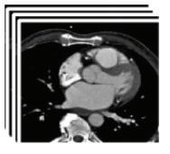
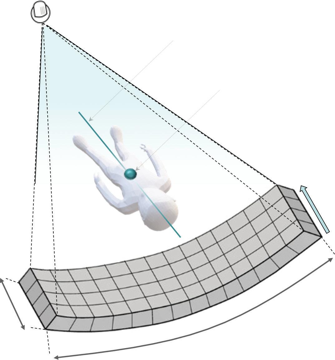
A CT detector is typically banana shaped, consisting of many thousand individual elements focused onto the focal spot of the X- ray source (Figure .2.3).
• The layout of the CT detector can be described along the fan direction by the number of detector channels in each individual detector row. This geometry is replicated over multiple slices along the (longitudinal) z- axis, resulting in a multislice detector. A modern CT system suitable for cardiac imaging should provide at least 64 detector rows.
• The width of each individual detector row or element is typically in the range of 0.5– 0.8 mm at the iso- centre.
• The total detector coverage in z- axis direction (detector collimation/physical collimation) is the product of the number of slices times the width of the detector element (slice width). A 64- row system with 0.625 mm slice width has a detector collimation of 40 mm at the iso- centre.
• The physical collimation is the primary factor determining the number of cardiac cycles required in a single cardiac scan range when different CT systems are compared. The comparison needs to be done using the same acquisition technique (e.g. prospective step- and- shoot and retrospective ECG- gated spiral) as there are large systematic differences between them.
• CT systems with a periodic motion of the tube focal spot in the z- direction (z-flying focal spot) create an oversampling of the slices in z- direction and ‘double’ their slices in the reconstruction process. These CT systems are often referenced by their effective doubled slice count instead of their physical detector slice count. The key parameters of current selected cardiac CT scanners are described in Table .2..
X-ray source
Isocentre Axis of rotation
Detector rows 64−320
Detector channels 600−1800
.2.3 Illustration of a detector array.
Adapted from Malajikian, K. and Finelli, D. Basics of Computed Tomography, Multimodality Imaging Guidance in Interventional Pain Management . Oxford University Press.
Spatial resolution
Spatial resolution is the ability to discern two objects as separate from one another.
• Spatial resolution plays an important role in the assessment of the severity of coronary stenosis and the overall interpretability of CCTA images. The term ‘isotropic’ indicates similar spatial resolution achieved in the in- plane (x- and yaxes) and through- plane (z- axis) directions.
• Sufficient spatial resolution is required for a detailed analysis of coronary plaque components.
• Insufficient spatial resolution leads to partial volume effects that may result in blooming artefacts from high- attenuating objects (calcified plaque, coronary stents), which can lead to overestimation of object size and the severity of stenosis
The spatial or high- contrast resolution of a CT system can be determined experimentally from phantom measurements of high- contrast objects with a very large ‘signal-to- noise’ ratio. The test measures the system’s ability to resolve objects of decreasing sizes by scanning, for example, a wire phantom or an aluminium bar pattern phantom. A CT system’s maximum spatial resolution, which can be achieved given a suitable reconstruction filter/kernel, is typically provided in units of ‘linepairs per cm’ (lp/cm). This ‘maximum’ resolution is closely: