Electronic Measurements and Instrumentation
K. LAL KISHORE
Rector
Jawaharlal Nehru Technological University Hyderabad, Hyderabad
Copyright © 2010 Dorling Kindersley (India) Pvt. Ltd
Licensees of Pearson Education in South Asia
No part of this eBook may be used or reproduced in any manner whatsoever without the publisher’s prior written consent.
This eBook may or may not include all assets that were part of the print version. The publisher reserves the right to remove any material present in this eBook at any time.
ISBN 9788131721995
eISBN 9789332500792
Head Office: A-8(A), Sector 62, Knowledge Boulevard, 7th Floor, NOIDA 201 309, India
Registered Office: 11 Local Shopping Centre, Panchsheel Park, New Delhi 110 017, India
Dedicated to The Almighty, who is omnipresent and omnipotent
This page is intentionally left blank.
1.Measurements and Instruments 1
2.Waveform Generators 103
3.Signal Analysers 119
4.Oscilloscopes 144
5.Special Types of CROs 190
6.DC and AC Bridges 224
7.Transducers 273
8.Other Types of Transducers 309
Brief Contents
This page is intentionally left blank.
Foreword xxi
Preface xxiii
About the Author xxv
1 Measurements and Instruments 1
1.1 Introduction 1
1.2 Terminology 2
1.2.1 Advantages of Instrumentation Systems 3
1.2.2 Block Schematics of Measuring Systems 3
1.2.3 Other Systems 4
1.2.4 Objectives of Measurement 5
1.2.5 Comparison Between Analog and Digital Instruments 5
1.2.6 Factors for the Selection of Analog and Digital Equipments 5
1.3 Performance Characteristics 6
1.3.1 Definitions 6
1.4 Significant Figures 8
1.5 Dynamic Characteristics 9
1.6 Types of Errors 11
1.6.1 Gross Errors 11
1.6.2 Systematic Errors 11
1.6.3 Random Errors 12
1.7 Statistical Analysis 12
1.7.1 Probability of Errors and Gaussian Curve 13
1.8 Measurement Standards 15
1.9 Suspension Galvanometer 17
1.10 D’Arsonval Movement 18
1.10.1 Taut-Band Suspension 20
1.10.2 Temperature Compensation 21
1.10.3 Shunt Resistor 22
1.10.4 Ayrton Shunt 22
1.11 Direct Current Meters 23
1.12 D’Arsonval Meter Movement Used in DC Voltmeters 27
1.12.1 Ammeter Loading Effect 29
1.13 DC Voltmeters 30
1.13.1 Multirange Voltmeter 31
1.14 Ohmmeter 32
1.14.1 Series-Type Ohmmeter 32
1.14.2 Shunt-Type Ohmmeter 33
1.14.3 D’Arsonval Meter Movement Used in Ohmmeter 33
1.14.4 Multiple Range Ohmmeters 35
1.14.5 Electrolyte Capacitor Leakage Tests 37
1.14.6 For Non-Electrolyte Capacitors 37
1.15 Multimeter 38
1.16 Alternating Current-Indicating Instruments 38
1.16.1 Electrodynamometer 40
1.17 Rectifier-Type Instruments 41
1.18 Meter Protection 42
1.19 Extension of Range 42
1.20 Frequency Compensation 44
1.21 Electronic Voltmeter (for DC) 47
1.22 Electronic Voltmeter (for AC) 48
1.22.1 Average Reading Voltmeter 49
1.22.2 Peak Reading Voltmeter 49
1.22.3 Peak-To-Peak Detector 50
1.23 DC Meter with Amplifier 51
1.24 Chopper-Stabilised Amplifier 52
1.25 AC Voltmeter using Rectifiers 53
1.26 True RMS-Responding Voltmeter 56
1.27 Balanced Bridge Voltmeter (VTVM) 57
1.27.1 Advantages 57
1.27.2 Disadvantages 58
1.28 Transistor Voltmeter (TVM) 58
1.29 Electronic Multimeter 58
1.29.1 Resistance Ranges 59
1.30 AC Current Measurement 61
1.30.1 Differential Voltmeter 61
1.31 Differential Amplifier 65
1.32 Alternating Current Instruments (AC Meters) 66
1.32.1 D’Arsonval Meter Movement for AC Circuit 66
1.32.2 Modified Circuit for AC Measurements 68
1.32.3 D’Arsonval Meter Movement Circuit (FWR) 69
1.33 Electrodynamometer Movement 70
1.33.1 Transfer Instruments 70
1.33.2 Iron Vane-Meter Movement 71
1.34 Thermocouple Meter 71
1.34.1 Constant Voltage Source 72
1.34.2 Constant Current Source 73
1.34.3 Volt Box 74
1.34.4 Factors to be Considered in the Selection of an Analog Voltmeter 75
1.35 Digital Voltmeters 76
1.35.1 General Specifications 76
1.36 Ramp-Type DVM 77
1.37 Staircase Ramp-Type DVM 79
1.38 Dual Slope Integrating-Type DVM 79
1.39 Successive-Approximation Conversion (SAC) 83
1.39.1 Block Schematic 84
1.40 Continuous Balance-Type DVM 85
1.41 Automatic Polarity Indication for DVM 86
1.42 Autoranging for DVM 87
1.42.1 Typical Case 88
1.43 3 3 4 Digit Display 89
1.44 Picoammeter 90
1.44.1 Applications 90
1.45 Low-Current Ammeter Applications 91
1.45.1 Wafer-Level Photodiode Testing 91
1.45.2 Monitoring and Control of Focused Ion Beam Currents 91
1.46 High-Resistance Measurements 91
1.47 Summary 100
2 Waveform Generators 103
2.1 Introduction 103
2.2 Considerations in Choosing an Oscillator or Signal Generator 104
2.3 Sine Wave Generator 104
2.4 Oscillator Circuit 105
2.5 Attenuator 106
2.6 Frequency-Synthesised Signal Generator 108
2.7 Sweep-Frequency Generator 109
2.8 Pulse and Square Wave Generator 111
2.9 Function Generator 112
2.10 Arbitrary Waveform Generator 112
2.10.1 Applications 113
2.11 Video Signal Generator 113
2.12 Summary 116
3 Signal Analysers
119
3.1 Introduction 119
3.2 Wave Analyser 119
3.3 AF Wave Analyser 120
3.4 High-Frequency Wave Analyser 121
3.4.1 Frequency Mixers 121
3.5 Harmonic Distortion 122
3.5.1 Tunable Selective Circuit 123
3.5.2 Disadvantages 123
3.5.3 Heterodyne Wave Analyser (Wavemeter) 123
3.5.4 Fundamental Suppression Method of Distortion Measurement 124
3.6 Heterodyne Wave Analyser 125
3.6.1 Applications of Wave Analysers 126
3.7 Tuned Circuit Harmonic Analyser 126
3.8 Heterodyne Harmonic Analyser or Wavemeter 127
3.9 Fundamental Suppression Harmonic Distortion Analyser 128
3.10 Spectrum Analyser 129
3.10.1 Characteristics of a Spectrum Analyser 131
3.10.2 Applications of a Spectrum Analyser 131
3.10.3 Basic Spectrum Analyser 131
3.10.4 Factors to be Considered in a Spectrum Analyser 133
3.11 Low-Frequency Spectrum Analyser 134
3.11.1 Applications 134
3.12 Power Analyser 135
3.12.1 Communications Signal Analyser 135
3.12.2 Logic Analysers 136
3.12.3 Network Monitoring System 136
3.12.4 System Architecture 136
3.12.5 Features 136
3.12.6 Applications 137
3.13 Capacitance–Voltage Analysers 137
3.14 Oscillators 138
3.14.1 Considerations in Choosing an Oscillator 138
3.15 Summary 142
4 Oscilloscopes 144
4.1 Introduction 144
4.2 Cathode Ray Oscilloscope 144
4.3 Block Diagram of a CRO 145
4.4 Cathode Ray Tube (CRT) 146
4.5 Graticules 148
4.6 Electrostatic Deflection Sensitivity 149
4.6.1 Design Criteria 151
4.7 Different Controls in a CRO 152
4.7.1 How to Operate a CRO 152
4.8 Time Base Generators 153
4.8.1 Time Base Circuits 154
4.9 Triggered Mode 156
4.9.1 Free-Running Mode 156
4.9.2 Synchronisation of the Sweep Circuit 157
4.9.3 Types of CROS 158
4.9.4 Sections of CRTs 158
4.9.5 Deflection Sensitivity Equation 158
4.10 Neon Time Base Circuit 159
4.10.1 Frequency of Neon Time Base 160
4.10.2 Neon Lamp 161
4.10.3 Free-Running Mode of CRO 161
4.10.4 Using CRO in Triggered Mode 162
4.10.5 Automode of Sweep 164
4.10.6 Normal Mode 164
4.11 Time Base Circuit for a General-Purpose CRO 165
4.11.1 Synchronisation Issues 166
4.11.2 Line Synchronisation 167
4.12 Lissajous Figures 169
4.13 Types of CRO Probes 175
4.13.1 Direct Probe 175
4.13.2 High-Impedance Probe 175
4.13.3 Detector Probe 176
4.13.4 High-Voltage Probe 177
4.14 High-Frequency CRO Considerations 178
4.15 Delay Lines in CROs 181
4.15.1 Lumped Parameter Delay Line 182
4.15.2 Distributed Parameter Delay Line 183
4.16 Applications of CRO 183
4.17 Summary 187
5 Special Types of CROs 190
5.1 Special Types of Oscilloscopes 190
5.2 Dual Beam CRO 191
5.3 Dual Trace CRO 192
5.4 Sampling Oscilloscope 192
5.4.1 Sampling Oscilloscopes — Vertical and Time Base 194
5.4.2 Sampling Vertical 194
5.4.3 Sampling Time Base 195
5.5 Storage Oscilloscopes 197
5.5.1 Mesh Storage 198
5.5.2 Variable Persistence 200
5.5.3 Phosphor Storage 200
5.5.4 Phosphor Characteristics 201
5.5.5 Persistence of Phosphor Materials 201
5.5.6 CRO Subsytems 202
5.6 Digital Storage CRO 203
5.6.1 CRO Probes 205
5.7 Frequency/Period-Timer/Counter Circuit 206
5.8 Frequency Measurement 211
5.9 Period Measurement 212
5.9.1 Advantages 214
5.10 Errors in Frequency/Period Measurements 214
5.10.1 Errors Because of Crystal Stability 215
5.11 Universal Counters 216
5.12 Extending the Range of Frequency Counters 216
5.13 Glossary 217
5.14 The ABC’s of Oscilloscopes 218
5.15 Summary 221 6 DC and AC Bridges 224
6.1 Introduction 224
6.2 DC Bridges 224
6.3 Wheatstone Bridge 225
6.3.1 Operation 225
6.3.2 Measurement Errors 226
6.3.3 Thevenin’s Equivalent Circuit 226
6.4 Kelvin Bridge 228
6.4.1 Kelvin Double Bridge 229
6.4.2 Applications 230
6.5 Strain Gauge Bridge Circuit 231
6.6 AC Bridges 234
6.6.1 General Form of Bridge Circuit 235
6.7 Maxwell Bridge 236
6.7.1 Phasor Diagram for the Maxwell Bridge 237
6.8 Hay Bridge 237
6.8.1 Phasor Diagram for Hay Bridge 239
6.9 Schering Bridge 240
6.9.1 Phasor Diagram for a Schering Bridge 241
6.10 Wien Bridge 241
6.10.1 Phasor Diagram for the Wien Bridge 243
6.11 Anderson Bridge 243
6.12 Resonance Bridge 245
6.13 Similar Angle Bridge 245
6.14 Radio Frequency Bridge (Subtitution Technique) 246
6.15 Wagner’s Ground Connection 247
6.16 Twin-T Null Network 248
6.17 Bridged-T Network 250
6.18 Detectors for AC Bridges 251
6.19 Phasor Diagrams 251
6.20 Recorders 252
6.20.1 Introduction 252
6.21 Strip-Chart Recorders 252
6.21.1 Galvanometric Recorders 253
6.21.2 Sensitivity 253
6.21.3 Transient Response 253
6.22 Pen-Driving Mechanism 254
6.23 Other Features 256
6.24 Servorecorders 256
6.25 Servobalancing Potentiometric Recorder 257
6.26 Characteristics of Typical Servorecorders 259
6.27 Oscillographic Recorders 260
6.28 Magnetic Tape Recorders 261
6.28.1 Direct AM Recording 261
6.28.2 Frequency Modulation Recording 262
6.29 Recorders (Contd.) 263
6.29.1 X–Y Recorders 263
6.29.2 Self-Balancing Potentiometers 263
6.29.3 Working of a Servotype Motor 264
6.29.4 Chopper 264
6.29.5 Servotype X–Y Recorders 264
6.29.6 Y-Scale 265
6.30 Galvonometer Oscillographs 265
6.30.1 Applications 266
6.31 Summary 269
7 Transducers 273
7.1 Introduction 273
7.1.1 Examples 273
7.2 Classification of Transducers 273
7.3 Active and Passive Transducers 275
7.3.1 Factors that Affect the Performance of a Transducer 275
7.3.2 Applications 275
7.4 Force and Displacement Transducers 275
7.4.1 Potentiometer 275
7.4.2 Potentiometric Transducer 276
7.4.3 Loading Effect on a Potentiometer 276
7.4.4 Resolution 280
7.4.5 Linear Potentiometers 281
7.4.6 Non-Linear Potentiometers 281
7.4.7 Noise 282
7.5 Resistance Strain Gauges 284
7.6 Bonded-Type Strain Gauges 287
7.6.1 Filament Construction 287
7.6.2 Materials of the Filament Wire 288
7.6.3 Base Carrier Material 288
7.6.4 Strain Gauge Cements 289
7.6.5 Temperature Effect on Strain Gauges 289
7.6.6 Measurement of Strain 290
7.6.7 Strain Gauge Circuitry 291
7.6.8 The Ballast Circuit 291
7.6.9 The Wheatstone Bridge Circuit 292
7.6.10 Circuit for Calibration 294
7.6.11 Mounting of Strain Gauges 295
7.6.12 Commercial Strain-Measuring Systems 296
7.6.13 Stress Measurement on Rotating Members 296
7.6.14 Special Problems in Strain Gauge Applications 297
7.6.15 Semiconductor Strain Gauges 297
7.7 Summary 306
8 Other Types of Transducers 309
8.1 Introduction 309
8.2 Resistance Thermometers 309
8.2.1 Self-Heating 311
8.2.2 Advantages of Wire Resistance Thermometers 313
8.2.3 Disadvantages 313
8.3 Semiconducting-Resistance Temperature Transducers (Thermistors) 313
8.3.1 Circuit Employed 314
8.3.2 Advantages 316
8.3.3 Disadvantages 316
8.4 Hot Wire Anemometer 316
8.4.1 Constant Current Type 317
8.4.2 Measurement of Direction of Average Flow 319
8.5 Other Variable Resistance Transducers 321
8.5.1 Contact Pressure Transducer 321
8.5.2 Humidity Measurement 321
8.5.3 Light 321
8.6 Variable Inductance Transducers 322
8.6.1 Linear Variable Differential Transformer (LVDT) 322
8.6.2 Applications of LVDT 325
8.6.3 LVDT Load Cells 329
8.7 Synchros 329
8.8 Variable Reluctance Accelerometer 334
8.8.1 Microsyn 336
8.9 Temperature Measurement 336
8.9.1 Electric Methods 336
8.9.2 Electrical Methods 337
8.10 Thermocouples 337
8.10.1 Thermocouple Junction 339
8.10.2 Thermocouple Insulation 339
8.10.3 Soldered, Drawn, or Rolled Sheathed Thermocouple Construction 339
8.10.4 Disposable-Tip Thermocouples 339
8.10.5 Homogeneity of Thermocouple Wires 341
8.10.6 Installation of Thermocouples 341
8.10.7 Cold Junction Compensation 341
8.10.8 Resistance Thermometry 342
8.11 Platinum Resistance Thermometers 343
8.12 Special Resistance Thermometer 343
8.12.1 Performance and Testing Procedure 344
8.12.2 Insulation Resistance 345
8.12.3 Vibration Resistance 345
8.13 Thermistors 345
8.13.1 Thermistor Construction Techniques 346
8.13.2 Thermistor Performance Characteristics 347
8.13.3 Applications of Thermistor 349
8.13.4 Sensistors 349
8.14 Digital Temperature-Sensing System 349
8.15 Miscellaneous Transducers 349
8.15.1 Flow Measurements 349
8.15.2 Ultrasonic Flow Meters 351
8.15.3 Electromagnetic Flow Meter 354
8.15.4 Theory of Head Flow Meters 355
8.15.5 Various Tap Connections 355
8.15.6 Advantages and Limitations 355
8.15.7 Characteristics of Head Flow Meters 356
8.16 Area Flow Meters 357
8.16.1 Rotameters 357
8.16.2 Piston-Type Area Meter 357
8.16.3 Laser Doppler Anemometer (LDA) 359
8.17 Positive Displacement Meters 361
8.17.1 Basic Requirements 361
8.17.2 Nutating Piston Meters 362
8.17.3 Rotating Meters 362
8.17.4 Oscillating Piston Meters 362
8.18 Magnetic Flow Meter 363
8.18.1 Flow Meter Requirements 363
8.19 Variable Capacitance Transducers 364
8.19.1 Advantages of Capacitance Transducers 365
8.19.2 Practical Capacitor Pickups 365
8.19.3 Feedback-Type Capacitance Pickup 366
8.19.4 Carbon Microphone 368
8.19.5 Circuitry for Capacitance Transducers 369
8.19.6 Frequency-Modulating Oscillator Circuit 369
8.19.7 Circuits Using DC Excitation 371
8.19.8 AC Bridges for Amplitude Modulation 372
8.19.9 Pulsewidth-Modulating Circuit 374
8.20 Piezoelectric Transducer 374
8.20.1 Materials 374
8.20.2 Equivalent Circuit 377
8.20.3 Piezoelectric Coefficients 379
8.20.4 Modes of Deformation 381
8.20.5 Multiple Arrangements (Stacks) 381
8.20.6 Bimorphs 381
8.20.7 Bimorph Twisters 382
8.20.8 General Form of Piezoelectric Transducers 382
8.20.9 Available Typical Piezoelectric Accelerometers 383
8.20.10 Shock Accelerometer 383
8.20.11 Environmental Effects 384
8.21 Magnetostrictive Transducers 385
8.21.1 Magnetostrictive Materials 385
8.21.2 Practical Forms of Transducers 386
8.21.3 Magnetostrictive Torque Transducers 387
8.21.4 Errors 387
8.21.5 Temperature 387
8.21.6 Variation of Supply Voltage 388
8.21.7 Eddy Currents 388
8.21.8 Input Impedance 388
8.22 Liquid-Level Measurement 388
8.22.1 Direct Methods 389
8.22.2 Indirect Liquid-Level Measurement 389
8.22.3 Capacitance-Level Gauge 390
8.23 Ultrasonic-Level Gauge 391
8.24 Measurement of Humidity and Moisture 391
8.25 Photoconductive Cells 391
8.26 Photo Pulse Pickup 392
8.27 Digital Encoders and Encoder Transducers 393
8.27.1 Shaft Position Encoders 393
8.27.2 Encoder Transducers 393
8.28 Fibre Optic Displacement Transducer 394
8.28.1 Absolute Motion Devices 395
8.28.3 Measurement of Velocity 396
8.28.4 Translational Velocity Transducer Moving Coil Pickup 397
8.29 DC Tachometer Generators for Rotary Velocity Measurement 397
8.29.1 AC Tachogenerator for Rotary Velocity Measurement 398
8.30 Force Measurements 398
8.30.1 Balance 398
8.30.2 Elastic Force Devices 399
8.31 Electromechanical Methods 400
8.32 Measurement of Pressure 401
8.32.1 Moderate Pressure Measurement 402
8.32.2 Manometers 402
8.33 Elastic Transducers 404
8.34 High-Pressure Measurement 408
8.35 Low-Pressure Measurement (Vacuum Measurement) 408
8.35.1 Thermal Conductivity Gauge or Pirani Gauge 408
8.36 Temperature Measurements 409
8.37 Data Acquisition Systems 410
8.38 Summary 413
Appendix A 417
References 420
Index 421
This page is intentionally left blank.
Foreword
It gives me immense pleasure to write a foreword for Electronic Measurements and Instrumentation. The author has extensive experience in teaching this subject to students of B.Tech and Electronics and Communication Engineering and has based this book on his insights into the training needs of those who have opted for this field of study.
Technical education is expanding rapidly and every year several new engineering colleges are coming up, particularly in the state of Andhra Pradesh. With an increased number of students choosing engineering education there is an urgent need for good textbooks in this discipline. As there is a dearth of well-written books which meet the requirement of subject coverage from the perspective of Indian students, this book by Dr Lal Kishore is an important contribution in this area. Written in a lucid style with a rich repository of pedagogical features, this book will be useful for undergraduate students of electronics and communication engineering, instrumentation engineering, and allied branches. This book will also be useful to AMIETE and AMIE (Electronics) students. The author has incorporated several illuminating features in this book, and these include:
1.Chapter outlines
2.Summaries at the end of each chapter
3.Points to remember covering important terms
4.Objective-type questions
5.Review questions
6.Solved and unsolved problems for each chapter
I am sure that this textbook will be beneficial to students and teachers as well.
Prof. D. N. Reddy Vice Chancellor Jawaharlal Nehru Technological University Hyderabad,
Hyderabad
This page is intentionally left blank.
Preface
The role of science is to discover the laws of nature, while the role of engineering and technology is to invent methods to apply these laws to serve human needs. The development of science began at a rapid pace in the 19th century, and it continues unabated to this day. Measurement plays an important role in the context of the progressive metamorphosis of science and technology. The subject of measurement is crucial to advancements in the field of electronics. It is interesting to note that time, as a parameter first attempted to be measured by primitive races, is the most accurate that can be studied by contemporary technology.
This textbook has been written against a backdrop of the imperative need to closely examine the science of measurement vis-à-vis its emergence as a discipline indispensable to the study of electronics and related fields. Though a number of textbooks have been written on the topic, a need was felt to address the typical difficulties faced by the student in learning the subject and to clearly explain the subtle points and principles involved. Written in a userfriendly manner, the book engages both the student and the teacher with its lucid style and focussed pedagogical features that include summary, points to remember, objective-type questions, review questions, and unsolved problems. The subject has been discussed with the undergraduate student in mind, and all topics generally covered at the undergraduate level are examined in this book. The reader is acquainted with specifications, parameters, and the typical values obtained during usage of the different types of instruments. The subject can be understood well when related numerical problems are solved. To this end, a number of problems are worked out in all chapters.
The textbook will be useful to students appearing for competitive examinations as well, since it includes the topics covered in a number of universities. It would also be beneficial to students of AMIETE, AMIE, M.Sc. (Electronics), and all programmes that include electronic measurements and instrumentation as a subject of study.
Suggestions and feedback to improve this book are welcome.
Acknowledgements
I am thankful to Dr. E. N. Ganesh, Assistant Professor, Department of Electrical Communication Engineering (ECE), BSA Crescent Engineering College, for his help in writing this textbook. I am also grateful to E. V. L. N. Rangacharyulu, Associate Professor, Department of ECE, Sri Indu College of Engineering and Technology, Hyderabad, for his inputs. A number
of textbooks, journals, instrument manuals, and data manuals have been referred to at the time of writing this book. Thanks are due to the authors of all these textbooks and research articles. I am obliged to M/s Tektronix Instruments, M/s Keithley Instruments, and M/s Peridot Technologies, Hyderabad, for providing technical information on various instruments.
Lal Kishore
K.
About the Author
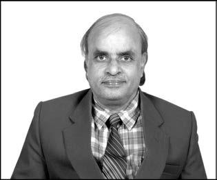
Professor K. Lal Kishore is a distinguished academician with over 30 years of teaching experience. He has several awards to his credit including one from Defence Engineering College, Ethiopia, for distinguished service and another from International Compendium for distinction in academics. A post-graduate and a Ph.D. degree-holder from the Indian Institute of Science Bangalore, Professor Kishore began his career in teaching at Jawaharlal Nehru Technological University (JNTU) Hyderabad in 1977. Appointed as professor of electrical communication engineering (ECE) in 1990, he has subsequently held many academic and administrative positions at JNTU Hyderabad including that of Chairman BOS; Head, Department of ECE; Principal; Academic; and Planning Director; UGC Academic Staff College; and Registrar. Currently he is Rector at JNTU Hyderabad.
With more than 76 research papers in national and international journals to his credit, Professor Kishore has presented several papers at national and international conferences and guided a number of research scholars. He was presented the Best Teacher Award for the year 2004 by the government of Andhra Pradesh. He has also received the S. V. C. Aiya Memorial Award and the Bapu Seetharam Memorial Award from the Institution of Electronics and Telecommunication Engineers (IETE).
A dedicated researcher in the field of electronics and telecommunications engineering, Professor Kishore is a member of the Institute of Electrical and Electronics Engineering (IEEE), Fellow of the Institute of Electronics and Telecommunication Engineers (IETE), and a lifetime member of the Indian Society of Technical Education (ISTE) and the International Society of Hybrid Microelectronics (ISHM)
This page is intentionally left blank.
Measurements and Instruments
Introduction
• Terminology
• Dynamic characteristics
• Performance characteristics • Significant figures
• Types of errors
• Statistical analysis
• Measurement standards
• Suspension galvanometer
• D’Arsonval movement • Direct current meter
• D’Arsonval meter movement used in DC voltmeters • DC voltmeter
• Ohmmeter • Multimeter
• Rectifier-type instruments
• Alternating current-indicating instruments
• Meter protection
• Extension of range • Frequency compensation
• Electronic voltmeter (for DC)
• DC meter with amplifier
• Electronic voltmeter (for AC)
• Chopper-stabilised amplifier • AC voltmeter using rectifiers • True RMS-responding voltmeter
• Balanced bridge voltmeter (VTVM)
• Transistor voltmeter (TVM)
• Electronic multimeter
• AC current measurement
• Differential amplifier
• Alternating current instruments (AC meters)
• Electrodynamometer movement
• Thermocouple meter • Digital voltmeter
• Ramp-type DVM • Staircase ramp-type DVM • Dual slope integrating-type DVM
• Successive-approximation conversion (SAC) • Continuous balance-type DVM
• 3 3 4 Digit display • Picoammeter • Low-current ammeter applications
• Automatic polarity indication for DVM • Autoranging for DVM
• High-resistance measurements
• Summary
1.1 INTRODUCTION
Although the measurement of simple physical parameters like time dates back to ancient times, measurement as a precise technology is only a few hundred years old. Perhaps, time was the first parameter measured by man. In olden days, time was measured during the day time by the position of sun in the sky. To count days or years, stones were placed at a particular position. Years were counted in the same way, by placing stones whenever a particular season arrived. The age of a person was also counted similarly. On the death of a person, the stones accumulated on his/her account were buried with his/her body. Though it is a crude technique, it was a kind of measurement. This method is still being followed as a ritual by some primitive races in Africa. Ironically, the same parameter ‘time’ is that which can be measured most precisely compared to other parameters. Cesium–Hydrogen atomic clocks have an accuracy of 1 sec in 30,000 years. When Galileo found the simple pendulum, clocks were built based on this principle. No other physical quantity can yet be measured with such an accuracy as time. The first major contribution to scientific instrumentation is from the science of optics. The telescope, the microscope, and the spectroscope were the first categories of scientific instruments. The spectroscope revealed new elements on Earth. The microscope showed that the cellular structure of living matter and microorganisms is the effective cause of diseases.
The role of science is to discover the laws of nature and how they operate in complex systems. The role of engineering is to apply the discoveries of science to human needs. Scientists make discoveries that increase our understanding of the world. Engineers make inventions intended to increase our productivity or ability to survive. Instrumentation is a branch of engineering that serves not only science but also all branches of engineering and medicine. The precise measurement of dimensions like temperature, pressure, power, voltage, current, impedance, etc., are as important to engineering as to science.
Accurate measurement is needed for economic design. A bridge several times stronger than needed to carry its heaviest possible load serves no one better and costs more. For millions of people watching TV, the dramatic moment of the Apollo-11 mission occurred when Neil Armstrong first set foot on the moon. But for many of the engineers who designed the lunar module, the dramatic moment occurred 2 hr earlier, when the lunar landing module set its feet on the moon. At that moment only 10 sec worth of fuel remained. Such a critical design was required since every gram of fuel saved could be used to increase the pay load of the lunar escape module.
The science of instrumentation plays an important role in technology. But electronics engineering plays a vital role in the field of instrumentation. The reason is that most physical quantities can be converted by transducers into electrical signals and once an electrical signal is available, the signal can be amplified, filtered, multiplexed, sampled, and measured. Nowadays, it is also possible to convert the signal into a digital form, interface it with a microprocessor (μP), or a microcontroller (μC), or a personal computer (PC) and can be monitored, controlled, and displayed effectively. The rapid strides made in semiconductor device technology and integrated circuits (IC) fabrication had its bearing on instrumentation also. The old instruments and systems using vacuum tubes were replaced by semiconductor devices and ICs. Now μP, μC, and PC-based measuring instruments and systems are the order of the day. Making use of the concept of composite materials, Thick-film Technology, Thinfilm Technology, Hybrid Microcircuits, and new types of sensors that are smaller in size and lesser in weight are being developed. By embedding a processor, memory, and digital display, intelligent sensors are being developed.
Thus, electronic measurements and instrumentation is a rapidly changing subject and contributes significantly to science and technology.
In this chapter, the construction and principle of the working of electronic instruments are explained. The measurement of voltage, current, and resistance is given with figures and circuits. In addition, extension of range of the instruments and frequency compensation techniques have been discussed.
Due to mechanical movement, electromechanical type of instruments for the measurement of voltage, current, and resistance have inherent disadvantages. In this chapter, electronic circuits used for the measurement of these parameters are described. The student is expected to understand the working of circuits and the advantages of these instruments over electromechanical types. Average reading, peak reading, true rms reading voltmeters, principle of operation, and working of these meters as well as electronic AC voltmeters, balanced bridge voltmeter circuits, operation, and working are to be learnt, from this chapter.
1.2 TERMINOLOGY
This subject has broadly two divisions, one dealing with measuring instruments called electronic measurements and the other dealing with transducer sensors, monitoring, and controlling physical
parameters called Instrumentation. In general, the manner in which instruments are put to use is classified as follows:
1. Monitoring of processes and operations.
2. Control of processes and operations.
3. Experimental engineering analysis.
This is only a general way of classification and there could be other applications as well.
Monitoring of processes and operations: Some measuring instruments have only a monitoring function; for example, thermometers and barometers. They simply indicate the condition of the environment and cannot control any function.
Control of processes and operations: Some instruments are put to use for the control of process operations; for example, home-heating system using a thermostat control. A temperature-measuring instrument senses the room temperature, thus providing information necessary for proper functioning of the control system. Missiles guided by the heat blast that is ejected from planes are another example.
Experimental engineering analysis: In research and development work, measuring instruments are used in carrying out experiments such as measurement of voltage, current, etc. Here the application of instruments is specifically intended for experimental purpose only.
1.2.1 Advantages of Instrumentation Systems
A few of the advantages of instrumentation systems include:
1. Remote measurement.
2. Accurate measurement.
3. Measurement in adverse conditions: nuclear reactors, space applications, etc.
4. Convenience: recording of data, printout, etc.
5. Reduction in size.
1.2.2 Block Schematics of Measuring Systems
Measurand: The quantity to be measured is called measurand.
Transducer: A device that converts a physical quantity into an electrical quantity or vice-versa.
Signal conditioner: Amplification, Filtering, Modulation, Demodulation, A/D conversion, etc.
Display/Record: The quantity is recorded using X–Y or strip-chart recorders or displayed on monitors, etc.
Any general measurement system as shown in Fig. 1.1 will have a transducer that converts the physical quantity into an electrical form, so that the signal may be modified suitably according to the requirements. Signal conditioning devices will carry out this task, and the parameter to be measured is displayed or recorded.
Figure 1.1 Block schematic of a general-purpose measuring system Display/ Record
