The rights of R. C. Hibbeler to be identified as the author of this work have been asserted by him in accordance with the Copyright, Designs and Patents Act 1988.
All rights reserved. No part of this publication may be reproduced, stored in a retrieval system, or transmitted in any form or by any means, electronic, mechanical, photocopying, recording or otherwise, without either the prior written permission of the publisher or a license permitting restricted copying in the United Kingdom issued by the Copyright Licensing Agency Ltd, Saffron House, 6–10 Kirby Street, London EC1N 8TS.
Many of the designations by manufacturers and seller to distinguish their products are claimed as trademarks. Where those designations appear in this book, and the publisher was aware of a trademark claim, the designations have been printed in initial caps or all caps. The author and publisher of this book have used their best efforts in preparing this book. These efforts include the development, research, and testing of theories and programs to determine their effectiveness.
The author and publisher make no warranty of any kind, expressed or implied, with regard to these programs or the documentation contained in this book. The author and publisher shall not be liable in any event for incidental or consequential damages with, or arising out of, the furnishing, performance, or use of these programs.
British Library Cataloguing-in-Publication Data
A catalogue record for this book is available from the British Library.
1 19
ISBN 10: 1-292-24713-4
ISBN 13: 978-1-292-24713-7
Printed in Malaysia (CTP-VVP)
To The Student
With the hope that this work will stimulate an interest in Structural Analysis and provide an acceptable guide to its understanding.
This page intentionally left blank
PREFACE
This book is intended to provide the student with a clear and thorough presentation of the theory and application of structural analysis as it applies to trusses, beams, and frames. Emphasis is placed on developing the student’s ability to both model and analyze a structure and to provide realistic applications encountered in professional practice.
For many years now, engineers have been using computer programs based on matrix methods to analyze structures. Although these methods are most efficient for a structural analysis, it is the author’s opinion that students taking a first course in this subject should also be well versed in some of the more important classical methods of structual analysis. By applying these methods it is possible to obtain a better understanding of how loads are transmitted through a structure, and how the structure will deform under load. These skills are also important for selecting a model of the structure that provides an accurate description of its behaviour. Finally the classical methods can be used to check computer results, rather than simply relying on the generated output.
New to this Edition. Several important new features are included in this edition.
Rewriting of Text Material. Concepts have been clarified and further expanded.
New Material Added Throughout. Chapters have been expanded with the addition of new material, including a discussion of catenary cables and further clarification for drawing moment and deflection diagrams for beams and frames.
New Problems. There are many new problems that have been added to this edition, along with the addition of preliminary problems.
Chapter Rearrangement. The chapter on approximate analysis has been placed later in the book, after the coverage of statically indeterminate structures.
Structural Modeling. The importance of being able to model a structure for use as input for a computer analysis is discussed throughout the book, and more specifically in Chapter 17.
ORGANIZATION AND APPROACH
The contents of each chapter are arranged into sections with specific topics categorized by title headings. Discussions relevant to a particular theory are succinct, yet thorough. In most cases, this is followed by a “procedure
for analysis” guide, which provides the student with a summary of the important concepts and a systematic approach for applying the theory. The example problems are solved using this outlined method in order to clarify its numerical application. Problems are given at the end of each chapter, and are arranged to cover the material in sequential order. Moreover, for any topic they are arranged in approximate order of increasing difficulty.
HALLMARK ELEMENTS
• Photographs. Many photographs are used throughout the book to explain how the principles of structural analysis apply to real-world situations.
• Problems. Most of the problems in the book depict realistic situations encountered in practice. It is hoped that this realism will both stimulate the student’s interest in structural analysis and develop the skill to reduce any such problem from its physical description to a model or symbolic representation to which the appropriate theory can be applied. All problems are in SI units. The intent has been to provide problems that test the student’s ability to apply the theory, keeping in mind that more complicated problems requiring tedious calculations can be relegated to computer analysis.
• Answers to Selected Problems. The answers to all but every fourth problem, indicated by an asterisk in the text, are listed in the back of the book. Extra care has been taken in the presentation and solution of the problems, and all the problem sets have been reviewed and the solutions checked and rechecked to ensure both their clarity and numerical accuracy.
• Example Problems. All the example problems are presented in a concise manner and in a style that is easy to understand.
• Illustrations. Throughout the book, an increase in two-color art has been added, including many photorealistic illustrations that provide a three-dimensional view for better understanding.
• Triple Accuracy Checking. This edition has undergone rigorous accuracy checking and proofing of pages. Besides the author’s review of all the pages and problems, a recheck was provided by K. Norlin of the Bittner Development Group, the Competentum team, specifically Pavel Kolmakov and Daria Zamiusskaya, K.B. Yap, and J.H. Lee.
• Preliminary and Fundamental Problems. These problem sets are selectively located at the end of many chapters. They offer students simple applications of the concepts and, therefore, provide them with the chance to develop their problem-solving skills before attempting to solve any of the standard problems that follow. You might consider these problems as
extended examples since they all have solutions and answers that are given in the back of the book. Additionally, the fundamental problems offer students an excellent means of studying for exams, and they can be used at a later time to prepare for various engineering exams.
CONTENTS
This book is divided into three parts. The first part covers the analysis for statically determinate structures. Chapter 1 provides a discussion of the various types of structural forms and loads. Chapter 2 discusses the determination of forces at the supports and connections of statically determinate beams and frames. The analysis of various types of statically determinate trusses is given in Chapter 3, and shear and bending-moment functions and diagrams for beams and frames are presented in Chapter 4. In Chapter 5, the analysis of simple cable and arch systems is presented, and in Chapter 6 influence lines for beams, girders, and trusses are discussed.
In the second part of the book, the analysis of statically indeterminate structures is considered. Geometrical methods for calculating deflections are discussed in Chapter 7. Energy methods for finding deflections are covered in Chapter 8. Chapter 9 covers the analysis of statically indeterminate structures using the force method of analysis, in addition to a discussion of influence lines for beams. Then the displacement methods consisting of the slope-deflection method in Chapter 10 and moment distribution in Chapter 11 are discussed. Using these methods, beams and frames having nonprismatic members are considered in Chapter 12. Finally, Chapter 13 discusses several common techniques that are used for an approximate analysis of a statically indeterminate structure.
The third part of the book treats the matrix analysis of structures using the stiffness method. Trusses are discussed in Chapter 14, beams in Chapter 15, and frames in Chapter 16. Finally, Chapter 17 provides some basic ideas as to how to model a structure, and for using available computer software for performing a structural analysis. A review of matrix algebra is given in Appendix A.
RESOURCES FOR INSTRUCTORS
• Mastering Engineering. This online Tutorial Homework program allows you to integrate dynamic homework with automatic grading. Mastering Engineering allows you to easily track the performance of your entire class on an assignment-by-assignment basis, or the detailed work of an individual student.
• Instructor’s Solutions Manual. An instructor’s solutions manual was prepared by the author. The manual was also checked as part of the Triple Accuracy Checking program. You can find the Solutions Manual on the Instructor Resource Center website www.pearsonglobaleditions.com.
• Presentation Resources. All art from the text is available in PowerPoint slide and JPEG format. These files are available for download from the Instructor Resource Center at www.pearsonglobaleditions.com. If you are in need of a login and password for this site, please contact your local Pearson representative.
• Video Solutions. Video solutions offer step-by-step solution walkthroughs of representative homework problems from each chapter of the text. Make efficient use of class time and office hours by showing students the complete and concise problem solving approaches that they can access anytime and view at their own pace. The videos are designed to be a flexible resource to be used however each instructor and student prefers. A valuable tutorial resource, the videos are also helpful for student self-evaluation as students can pause the videos to check their understanding and work alongside the video. Access the videos at www.pearsonglobaleditions.com and follow the links for the Structural Analysis text.
• Companion Website. The companion website, located at www. pearsonglobaleditions.com, includes opportunities for practice and review including video solutions, which provide complete, step-by-step solution walkthroughs of representative homework problems from each chapter. The videos offer:
■ Fully-worked Solutions—Showing every step of representative homework problems, to help students make vital connections between concepts.
■ Self-paced Instruction—Students can navigate each problem and select, play, rewind, fast-forward, stop, and jump-to-sections within each problem’s solution.
■ 24/7 Access—Help whenever students need it.
ACKNOWLEDGMENTS
Through the years, over one hundred of my colleagues in the teaching profession and many of my students have made valuable suggestions that have helped in the development of this book, and I would like to hereby acknowledge all of their comments. I personally would like to thank the reviewers contracted by my editor for this new edition, namely:
S. Chao, University of Texas, Arlington
P. Gardoni, University of Illinois at Urbana-Champaign
J. Marshall, Auburn University
V. May, Dartmouth College
T. Miller, Oregon State University
H. Najm, Rutgers University
T. Ross, University of New Mexico
S. Vukazich, San Jose State University
Also, the constructive comments from Kai Beng Yap, a practicing engineers, and Jun Hwa Lee are greatly appreciated. Finally, I would like to acknowledge the support I received from my wife Conny, who has always been very helpful in preparing the manuscript for publication. I would greatly appreciate hearing from you if at any time you have any comments or suggestions regarding the contents of this edition.
Russell
Charles Hibbeler hibbeler@bellsouth.net
GLOBAL EDITION
The publishers would like to thank the following for their contribution to the Global Edition:
Contributor for the Ninth and Tenth Editions in SI Units
Kai Beng Yap is currently a registered professional engineer who works in Malaysia. He has BS and MS degrees in civil engineering from the University of Louisiana, Lafayette, Louisiana; and has done further graduate work at Virginia Tech in Blacksburg, Virginia. He has taught at the University of Louisiana and worked as an engineering consultant in the areas of structural analysis and design, and the associated infrastructure.
Co-contributor for the Tenth Edition in SI Units
Farid Abed is currently a faculty member in the Department of Civil Engineering at the American University of Sharjah, where he teaches undergraduate courses in structural analysis and mechanics and graduate courses in advanced structural analysis and computational mechanics to civil engineering students. He received his PhD degree in civil engineering from Louisiana State University, and his research interests include computational solid and structural mechanics, advanced mechanics of materials, nonlinear finite elements, and damage mechanics.
Reviewers for the Tenth Edition in SI Units
Farid Abed, American University of Sharjah
Imad Abou-Hayt, University of Aalborg
Samit Ray Chaudhuri, Indian Institute of Technology Kanpur
Kevin Kuang Sze Chiang, National University of Singapore
2.6 Application of the Equations of Equilibrium 74 Fundamental Problems 84 Problems 86 Project Problem 95 Chapter Review 96
4
Internal Loadings Developed in Structural Members 154
4.1 Internal Loadings at a Specified Point 155
4.2 Shear and Moment Functions 161
4.3 Shear and Moment Diagrams for a Beam 166
4.4 Shear and Moment Diagrams for a Frame 176
4.5 Moment Diagrams Constructed by the Method of Superposition 181 Preliminary Problems 188 Fundamental Problems 190 Problems 194 Project Problems 204 Chapter Review 205
5
3 Cables and Arches 206
2 Analysis of Statically Determinate Trusses 98
3.1 Common Types of Trusses 99
3.2 Classification of Coplanar Trusses 105
3.3 The Method of Joints 112
3.4 Zero-Force Members 116
3.5 The Method of Sections 118
3.6 Compound Trusses 124
3.7 Complex Trusses 128
3.8 Space Trusses 132 Fundamental Problems 139 Problems 141
Project Problem 151 Chapter Review 152
5.1 Cables 207
5.2 Cable Subjected to Concentrated Loads 208
5.3 Cable Subjected to a Uniform Distributed Load 210
15.4 Application of the Stiffness Method for Beam Analysis 613 Problems 626
Plane Frame Analysis Using the Stiffness Method 628
16.1 Frame-Member Stiffness Matrix 629
16.2 Displacement and Force Transformation Matrices 631
16.3 Frame-Member Global Stiffness Matrix 633
16.4 Application of the Stiffness Method for Frame Analysis 634 Problems 643
Structural Modeling and Computer Analysis 646
17.1 General Structural Modeling 647
17.2 Modeling a Structure and its Members 649
17.3 General Application of a Structural Analysis Computer Program 654 Computer Problems 659 Project Problems 661
Appendix
A Matrix Algebra for Structural Analysis 664
Preliminary and Fundamental Problem Solutions 677
Answers to Selected Problems 705 Index 723
This page intentionally left blank
STRUCTURAL ANALYSIS
CHAPTER 1
@ Carlo Allegri/GettyImages
Severe wind loadings caused by a hurricane have caused noticeable damage to the windows of this high-rise building.
TYPES OF STRUCTURES AND LOADS
CHAPTER OBJECTIVES
To introduce the basic types of structures.
To provide a brief explanation of the various types of loads that must be considered for an appropriate analysis and design.
1.1 INTRODUCTION
In this book we will present many of the different ways engineers model and then determine the loadings and deflections of various types of structures. Important examples related to civil engineering include buildings, bridges, and towers; and in other branches of engineering, ship and aircraft frames, mechanical systems, and electrical supporting structures are important.
Throughout this book, a structure refers to any system of connected parts used to support a load. When designing a structure to serve a specified function for public use, the engineer must account for its safety, esthetics, and serviceability, while taking into consideration economic and environmental constraints. For any project this often requires several independent studies, using different structural forms, before a final judgment can be made as to which form is most appropriate. This design process is both creative and technical and requires a fundamental knowledge of material properties and the laws of mechanics which govern material response. Once a preliminary design of a structure is
proposed, the structure must then be analyzed to ensure that it has its required stiffness, strength, and stability. To do this, an idealization must be made as to how all members are supported and connected together. Then the loadings are determined from codes and local specifications. Finally, the forces in the members and their displacements are found using the theory of structural analysis, which is the subject matter of this book.
1.2 CLASSIFICATION OF STRUCTURES
It is important for a structural engineer to recognize the various types of elements composing a structure and to be able to classify structures as to their form and function. We will introduce some of these aspects now and discuss others throughout the book.
Structural Elements. Some of the more common elements from which structures are composed are as follows.
Tie Rods. Structural members that are subjected to a tensile force are often referred to as tie rods or bracing struts. These members are rather slender, and are often chosen from rods, bars, angles, or channels, Fig. 1–1.
Fig. 1–1
Tie rods are used for cross bracing to stiffen the roof of a building to resist wind loads.
Beams. Beams are usually straight horizontal members used primarily to carry vertical loads. Quite often they are classified according to the way they are supported, as indicated in Fig. 1–2. In particular, when the cross section varies the beam is referred to as a tapered or haunched beam. Beam cross sections may also be “built up” by adding plates to their top and bottom.
Beams are primarily designed to resist bending moment; however, if they are short and carry large loads, the internal shear force may become quite large and this force may govern their design. When the material used for a beam is a metal such as steel or aluminum, the cross section is most efficient when it is shaped as shown in Fig. 1–3. Here the forces developed in the top and bottom flanges of the beam form the necessary couple used to resist the applied moment M, whereas the web is effective in resisting the applied shear V. This cross section is commonly referred to as a wide flange, and it is normally formed as a single unit in a rolling mill in lengths up to 23 m. When the beam is required to have a very long span, and the loads applied are rather large, the cross section may take the form of a plate girder. This member is fabricated by using a large plate for the web and welding or bolting plates to its ends for flanges. The girder is often transported to the field in segments, and the segments are designed to be spliced or joined together at points where the girder carries a small internal moment.
Concrete beams generally have rectangular cross sections, since it is easy to construct this form directly on the job site. Because concrete is rather weak in resisting tension, steel “reinforcing rods” are cast into the beam within regions of the cross section subjected to tension. Precast concrete beams or girders have a variety of different cross sections, and so they are fabricated at a shop or yard and then transported to the job site.
Beams made from timber may be sawn from a solid piece of wood or laminated. Laminated beams, often called glulam beams, are constructed from strips of wood, which are fastened together using high-strength glues.
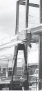
Shown are typical splice plate joints used to connect the steel plate girders of a highway bridge.
The prestressed concrete girders are simply supported on the piers and are used for this highway bridge.
Fig. 1–2
Fig. 1–3
Wide-flange members are often used for columns. Here is an example of a beam column.
Columns. Members that are generally vertical and resist axial compressive loads are referred to as columns, Fig. 1–4. Tubes and wideflange cross sections are often used for metal columns, and circular and square cross sections with reinforcing rods are used for those made of concrete. Occasionally, columns are subjected to both an axial load and a bending moment as shown in the figure. These members are referred to as beam columns.
Types of Structures. A combination of structural elements is referred to as a structural system. Each system is constructed of one or more of four basic types of structures. Ranked in order of complexity of their force analysis, they are as follows.
Trusses. When the span of a structure is required to be long and its depth is not an important criterion for design, a truss may be selected. Trusses consist of slender elements, usually arranged as a series of triangular elements. Planar trusses are composed of members that lie in the same plane and are frequently used for bridge and roof support, whereas space trusses have members extending in three dimensions and are suitable for derricks and towers.
A truss supports its load through the tension and compression of its members, and as a result a truss uses less material than a solid beam to support a given load, Fig. 1–5. In general it is economically feasible to use a truss to cover spans ranging from 9 m to 122 m, although trusses have been used on occasion for spans of greater lengths.
beam column column
Fig. 1–4
An applied loading will cause bending of this truss, which develops compression in the top members and tension in the bottom members.
Cables and Arches. Two other forms of structures used to span long distances are the cable and the arch. Cables are usually flexible and carry their loads in tension, Fig. 1–6a. They are commonly used to support bridges and building roofs. When used for these purposes, the cable has an advantage over the beam and the truss, especially for spans that are greater than 46 m. Because they are always in tension, cables will not become unstable and suddenly collapse or buckle, as may happen with beams or trusses. The use of cables, on the other hand, is limited only by their sag, weight, and methods of anchorage.
The arch achieves its strength in compression, since it has a reverse curvature to that of the cable. The arch must be rigid, however, in order to maintain its shape. Arches are frequently used in bridge structures, Fig. 1–6b, dome roofs, and for openings in masonry walls.
Fig. 1–5
Fig. 1–6
Cables support their loads in tension. (a) Arches support their loads in compression. (b)
Frame members are subjected to internal axial, shear, and moment loadings.
Frames. Frames are often used in buildings and are composed of beams and columns that are either pin or fixed connected, Fig. 1–7. Like trusses, frames extend in two or three dimensions.
Surface Structures. A surface structure is made of a material having a very small thickness compared to its other dimensions. Sometimes this material is very flexible and can take the form of a tent or air-inflated structure. In either case the material acts as a membrane that is subjected to pure tension.
Surface structures may also be made of rigid material such as reinforced concrete. As such they may be shaped as folded plates, cylinders, or hyperbolic paraboloids, and in any of these forms, they are referred to as thin plates or shells. In general, these types of structures are difficult to analyze, due to the three-dimensional geometry of their surface. Such an analysis is beyond the scope of this book and is instead covered in books devoted entirely to this subject.
The roof of the “Georgia Dome” in Atlanta, Georgia can be considered as a thin membrane.
Fig. 1–7
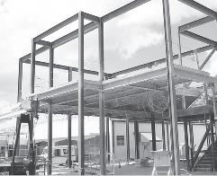
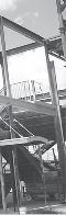
Typical steel framework.
1.3
LOADS
Once the dimensional requirements for a structure have been defined, it becomes necessary to determine the loads the structure must support. Often, it is the anticipation of the various loads that will be imposed on the structure that provides the basic type of structure that will be chosen for design. For example, high-rise structures must endure large lateral loadings caused by wind, and so shear walls and tubular frame systems are selected, whereas buildings located in areas prone to earthquakes must be designed having ductile frames and connections.
The actual design begins with those elements that are subjected to the primary loads the structure is intended to carry, and proceeds in sequence to the various supporting members until the foundation is reached. Thus, a building floor slab would be designed first, followed by the supporting beams, columns, and last, the foundation footings. In order to design a structure, it is therefore necessary to first specify the loads that act on it.
The design loading for a structure is often specified in codes. In general, the structural engineer works with two types of codes. General building codes specify the requirements of governmental bodies or organizations for minimum design loads, and design codes provide detailed technical standards that are used to establish the requirements for the actual structural design. Table 1.1 lists some of the important codes used in practice. It should be realized, however, that codes provide only a general guide for design. The ultimate responsibility for the design lies with the structural engineer.
Since a structure is generally subjected to several types of loads, a brief discussion of these loadings will now be presented to illustrate how one must consider their effects in practice.
TABLE 1.1 Codes
General Building Codes
Minimum Design Loads for Buildings and Other Structures, ASCE/SEI 7-16, American Society of Civil Engineers
International Building Code
Design Codes
Building Code Requirements for Reinforced Concrete, Am. Conc. Inst. (ACI)
Manual of Steel Construction, American Institute of Steel Construction (AISC)
Standard Specifications for Highway Bridges, American Association of State Highway and Transportation Officials (AASHTO)
National Design Specification for Wood Construction, American Forest and Paper Association (AFPA)
Manual for Railway Engineering, American Railway Engineering and Maintenance-of-Way Association (AREMA)
Dead Loads. Dead loads consist of the weights of the various structural members and the weights of any objects that are permanently attached to the structure. Hence, for a building, the dead loads include the weights of the columns, beams, and girders, the floor slab, roofing, walls, windows, plumbing, electrical fixtures, and other miscellaneous attachments.
In some cases, a structural dead load can be estimated satisfactorily from simple formulas based on the weights and sizes of similar structures. Also, through experience one can sometimes derive a “feeling” for the magnitude of these loadings before doing any calculations to verify a result.
TABLE 1.2 Minimum Densities for Design Loads from Materials*
*Minimum Densities for Design Loads from Materials. Reproduced with permission from American Society of Civil Engineers Minimum Design Loads for Buildings and Other Structures, ASCE/SEI 7-16. Copies of this standard may be purchased from ASCE at www.asce. org/publications.
*Minimum Design Dead Loads. Reproduced with permission from American Society of Civil Engineers Minimum Design Loads for Buildings and Other Structures, ASCE/SEI 7-16, American Society of Civil Engineers.
TABLE 1.3 Minimum Design Dead Loads*
If the materials and sizes of the various components of the structure are known, then their weights can be found from tables that list their densities. For example, the densities of typical materials used in construction are listed in Table 1. 2, and a portion of a table listing the weights of typical building components is given in Table 1. 3. Although calculation of dead loads based on the use of tabulated data is rather straightforward, realize that these loads will have to be estimated in the initial phase of design. These estimates must include nonstructural materials such as electrical and plumbing systems. Furthermore, even if a building material is known, its unit weight as reported in codes may vary from that given by manufacturers. Also, because some changes in dead loading may occur during the lifetime of the building, estimates of dead loading can be in error by 15% to 20% or more. Normally, however, the dead load is not large compared to the design load for simple structures such as a beam or a single-story frame; however, for multistory buildings it is important to have an accurate accounting of all the dead loads in order to properly design the columns, especially for the lower floors.
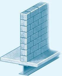
The floor beam in Fig. 1–8 is used to support the 1.8 m width of a lightweight plain concrete slab having a thickness of 100 mm. The slab serves as a portion of the ceiling for the floor below, and therefore its bottom is coated with plaster. Furthermore, a 3 m-high, 300-mm-thick lightweight concrete block wall is directly over the top flange of the beam. Determine the loading on the beam measured per meter of length of the beam.
SOLUTION
Using the data in Tables 1.2 and 1.3, we have Concrete slab: Plaster ceiling: Block wall: Total load 3 0.015 kN > ( m2 # mm ) 4 (100 mm)(1.8 m) = 2.70 kN > m ( 0.24 kN > m2 ) (1.8 m) = 0.43 kN > m ( 16.5 kN > m3 ) (3 m)(0.3 m) =
Fig. 1–8
EXAMPLE 1.1
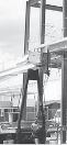
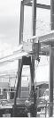
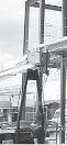
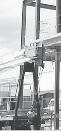
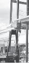
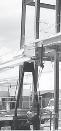
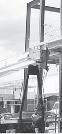
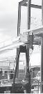
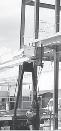
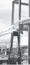
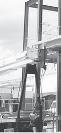
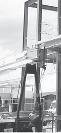
It is important to find the position of this moving load where it causes the largest compression in this bridge pier.
Live Loads. Live loads can vary both in their magnitude and location. They may be caused by the weights of objects temporarily placed on a structure, by moving vehicles, or by natural forces. The following are important examples of live loads that must be considered when designing a structure.
Building Loads. The floors of buildings are assumed to be subjected to uniform live loads, which depend on the purpose for which the building is designed. A representative sample of such minimum live loadings, taken from the ASCE 7-16 Standard, is shown in Table 1.4. The values are determined from a history of loading various buildings, and they include some protection against the possibility of overload, which can occur during construction or from vibrations while the building is in service. In addition to uniform distributed loads, some codes specify minimum concentrated live loads, caused by hand carts, automobiles, etc., which must also be applied to the floor system. For example, both uniform and concentrated live loads must be considered in the design of an automobile parking deck.
TABLE 1.4 Minimum Live Loads*
Assembly areas and theaters
*Minimum Live Loads. Reproduced with permission from American Society of Civil Engineers Minimum Design Loads for Buildings and Other Structures, ASCE/SEI 7-16, American Society of Civil Engineers.
For buildings having very large floor areas, many codes will allow a reduction in the uniform live load for the floor, since it is unlikely that the prescribed live load will occur simultaneously throughout the entire structure at any one time. For example, ASCE 7-16 allows a reduction of live load on a member having an influence area (KLLAT) of 37.2 m2 or more. This reduced live load is calculated using the following equation:
where
L = reduced design live load per square meter of floor area supported by the member.
L0 = unreduced design live load per square meter of area supported by the member (see Table 1.4).
KLL = live load element factor. For interior columns KLL = 4. AT = tributary area in square meters.*
The reduced live load defined by Eq. 1–1 is limited to not less than 50% of L0 for members supporting one floor, or not less than 40% of L0 for members supporting more than one floor. No reduction is allowed for loads exceeding 4.79 kN > m2 on a member supporting one floor, or for a passenger vehicle garage.
*Examples of tributary areas for beams and columns are given in Sec. 2.1.