PREFACE
The objective ofthis book is to provide the techniques necessary to study the motion ofmachines.A focus is placed on the application ofkinematic theories to real-world machinery. It is intended to bridge the gap between a theoretical study of kinematics and the application to practical mechanisms. Students completing a course ofstudy using this book should be able to determine the motion characteristics ofa machine. The topics presented in this book are critical in machine design process as such analyses should be performed on design concepts to optimize the motion ofa machine arrangement.
This fourth edition incorporates much ofthe feedback received from instructors and students who used the first three editions.Some enhancements include a section introducing special-purpose mechanisms;expanding the descriptions of kinematic properties to more precisely define the property; clearly identifying vector quantities through standard boldface notation;including timing charts;presenting analytical synthesis methods;clarifying the tables describing cam follower motion;and adding a standard table used for selection of chain pitch.The end-of-chapter problems have been reviewed. In addition,many new problems have been included.
It is expected that students using this book will have a good background in technical drawing,college algebra,and trigonometry.Concepts from elementary calculus are mentioned,but a background in calculus is not required. Also,knowledge ofvectors,mechanics,and computer application software,such as spreadsheets,will be useful. However,these concepts are also introduced in the book.
The approach ofapplying theoretical developments to practical problems is consistent with the philosophy of engineering technology programs.This book is primarily oriented toward mechanical- and manufacturing-related engineering technology programs.It can be used in either associate or baccalaureate degree programs.
Following are some distinctive features ofthis book:
1. Pictures and sketches ofmachinery that contain mechanisms are incorporated throughout the text.
2. The focus is on the application ofkinematic theories to common and practical mechanisms.
3. Both graphical techniques and analytical methods are used in the analysis ofmechanisms.
4. An examination copy ofWorking Model®,a commercially available dynamic software package (see Section 2.3 on page 32 for ordering information),is extensively used in this book.Tutorials and problems that utilize this software are integrated into the book.
5. Suggestions for implementing the graphical techniques on computer-aided design (CAD) systems are included and illustrated throughout the book.
6. Every chapter concludes with at least one case study. Each case illustrates a mechanism that is used on industrial equipment and challenges the student to discuss the rationale behind the design and suggest improvements.
7. Both static and dynamic mechanism force analysis methods are introduced.
8. Every major concept is followed by an example problem to illustrate the application ofthe concept.
9. Every Example Problem begins with an introduction ofa real machine that relies on the mechanism being analyzed.
10. Numerous end-of-chapter problems are consistent with the application approach ofthe text.Every concept introduced in the chapter has at least one associated problem.Most ofthese problems include the machine that relies on the mechanism being analyzed.
11. Where applicable,end-of-chapter problems are provided that utilize the analytical methods and are best suited for programmable devices (calculators, spreadsheets,math software,etc.).
Initially,I developed this textbook after teaching mechanisms for several semesters and noticing that students did not always see the practical applications ofthe material.To this end,I have grown quite fond ofthe case study problems and begin each class with one.The students refer to this as the “mechanism ofthe day.”I find this to be an excellent opportunity to focus attention on operating machinery. Additionally,it promotes dialogue and creates a learning community in the classroom.
Finally,the purpose ofany textbook is to guide the students through a learning experience in an effective manner.I sincerely hope that this book will fulfill this intention.I welcome all suggestions and comments and can be reached at dmyszka@udayton.edu.
ACKNOWLEDGMENTS
I thank the reviewers ofthis text for their comments and suggestions:Dave Brock,Kalamazoo Valley Community College;Laura Calswell,University ofCincinnati;Charles Drake,Ferris State University;Lubambala Kabengela, University ofNorth Carolina at Charlotte;Sung Kim, Piedmont Technical College;Michael J.Rider,Ohio Northern University;and Gerald Weisman,University of Vermont. DaveMyszka
CONTENTS
1Introduction to Mechanisms and Kinematics1
Objectives1
1.1Introduction1
1.2Machines and Mechanisms1
1.3Kinematics2
1.4Mechanism Terminology2
1.5Kinematic Diagrams4
1.6Kinematic Inversion8
1.7Mobility8
1.7.1Gruebler’s Equation8
1.7.2Actuators and Drivers12
1.8Commonly Used Links and Joints14
1.8.1Eccentric Crank14
1.8.2Pin-in-a-Slot Joint14
1.8.3Screw Joint15
1.9Special Cases ofthe Mobility Equation16
1.9.1Coincident Joints16
1.9.2Exceptions to the Gruebler’s Equation18
1.9.3Idle Degrees ofFreedom18
1.10The Four-Bar Mechanism19
1.10.1Grashof’s Criterion19
1.10.2Double Crank20
1.10.3Crank-Rocker20
1.10.4Double Rocker20
1.10.5Change Point Mechanism20
1.10.6Triple Rocker20
1.11Slider-Crank Mechanism22
1.12Special Purpose Mechanisms22
1.12.1Straight-Line Mechanisms22
1.12.2Parallelogram Mechanisms22
1.12.3Quick-Return Mechanisms23
1.12.4Scotch Yoke Mechanism23
1.13Techniques ofMechanism Analysis23
1.13.1Traditional Drafting Techniques24
1.13.2CAD Systems24
1.13.3Analytical Techniques24
1.13.4Computer Methods24
Problems25
Case Studies29
2Building Computer Models of Mechanisms Using Working Model® Software31
Objectives31
2.1Introduction31
2.2Computer Simulation ofMechanisms31
2.3Obtaining Working Model Software32
2.4Using Working Model to Model a Four-Bar Mechanism32
2.5Using Working Model to Model a SliderCrank Mechanism37
Problems41
Case Studies42
3Vectors43
Objectives43
3.1Introduction43
3.2Scalars and Vectors43
3.3Graphical Vector Analysis43
3.4Drafting Techniques Required in Graphical Vector Analysis44
3.5CAD Knowledge Required in Graphical Vector Analysis44
3.6Trigonometry Required in Analytical Vector Analysis44
3.6.1Right Triangle44
3.6.2Oblique Triangle46
3.7Vector Manipulation48
3.8Graphical Vector Addition 48
3.9Analytical Vector Addition :Triangle Method50
3.10Components ofa Vector52
3.11Analytical Vector Addition :Component Method53
3.12Vector Subtraction 55
3.13Graphical Vector Subtraction 55
3.14Analytical Vector Subtraction :Triangle Method57
3.15Analytical Vector Subtraction : Component Method59
3.16Vector Equations60
3.17Application ofVector Equations62
3.18Graphical Determination ofVector Magnitudes63
3.19Analytical Determination ofVector Magnitudes66
Problems67
Case Studies71
4Position and Displacement Analysis72
Objectives72
4.1Introduction72
4.2Position72
4.2.1Position ofa Point72
4.2.2Angular Position ofa Link72
4.2.3Position ofa Mechanism73
4.3Displacement73
4.3.1Linear Displacement73
4.3.2Angular Displacement73
4.4Displacement Analysis74
4.5Displacement:Graphical Analysis74
4.5.1Displacement ofa Single Driving Link74
4.5.2Displacement ofthe Remaining Slave Links75
4.6Position:Analytical Analysis79
4.6.1Closed-Form Position Analysis Equations for an In-Line Slider-Crank81
4.6.2Closed-Form Position Analysis Equations for an Offset SliderCrank84
4.6.3Closed-Form Position Equations for a Four-Bar Linkage87
4.6.4Circuits ofa Four-Bar Linkage87
4.7Limiting Positions:Graphical Analysis87
4.8Limiting Positions:Analytical Analysis91
4.9Transmission Angle93
4.10Complete Cycle:Graphical Position Analysis94
4.11Complete Cycle:Analytical Position Analysis96
4.12Displacement Diagrams98
4.13Coupler Curves101
Problems101
Case Studies108
5Mechanism Design109
Objectives109
5.1Introduction109
5.2Time Ratio109
5.3Timing Charts110
5.4Design ofSlider-Crank Mechanisms113
5.4.1In-Line Slider-Crank Mechanism113
5.4.2Offset Slider-Crank Mechanism114
5.5Design ofCrank-Rocker Mechanisms115
5.6Design ofCrank-Shaper Mechanisms117
5.7Mechanism to Move a Link Between Two Positions118
5.7.1Two-Position Synthesis with a Pivoting Link118
5.7.2Two-Position Synthesis ofthe Coupler ofa Four-Bar Mechanism118
5.8Mechanism to Move a Link Between Three Positions119
5.9Circuit and Branch Defects119
Problems120
Case Studies121
6Velocity Analysis123
Objectives123
6.1Introduction123
6.2Linear Velocity123
6.2.1Linear Velocity ofRectilinear Points123
6.2.2Linear Velocity ofa General Point124
6.2.3Velocity Profile for Linear Motion124
6.3Velocity ofa Link125
6.4Relationship Between Linear and Angular Velocities126
6.5Relative Velocity128
6.6Graphical Velocity Analysis:Relative Velocity Method130
6.6.1Points on Links Limited to Pure Rotation or Rectilinear Translation130
6.6.2General Points on a Floating Link132
6.6.3Coincident Points on Different Links135
6.7Velocity Image137
6.8Analytical Velocity Analysis:Relative Velocity Method137
6.9Algebraic Solutions for Common Mechanisms142
6.9.1Slider-Crank Mechanism142
6.9.2Four-Bar Mechanism142
6.10Instantaneous Center ofRotation142
6.11Locating Instant Centers142
6.11.1Primary Centers143
6.11.2Kennedy’s Theorem144
6.11.3Instant Center Diagram144
6.12Graphical Velocity Analysis:Instant Center Method149
6.13Analytical Velocity Analysis:Instant Center Method152
6.14Velocity Curves155
6.14.1Graphical Differentiation157
6.14.2Numerical Differentiation159 Problems161
Case Studies168
7Acceleration Analysis170
Objectives170
7.1Introduction170
7.2Linear Acceleration170
7.2.1Linear Acceleration ofRectilinear Points170
7.2.2Constant Rectilinear Acceleration171
7.2.3Acceleration and the Velocity Profile171
7.2.4Linear Acceleration ofa General Point173
7.3Acceleration ofa Link173
7.3.1Angular Acceleration173
7.3.2Constant Angular Acceleration173
7.4Normal and Tangential Acceleration174
7.4.1Tangential Acceleration174
7.4.2Normal Acceleration175
7.4.3Total Acceleration175
7.5Relative Motion177
7.5.1Relative Acceleration177
7.5.2Components ofRelative Acceleration179
7.6Relative Acceleration Analysis:Graphical Method181
7.7Relative Acceleration Analysis:Analytical Method188
7.8Algebraic Solutions for Common Mechanisms190
7.8.1Slider-Crank Mechanism190
7.8.2Four-Bar Mechanism191
7.9Acceleration ofa General Point on a Floating Link191
7.10Acceleration Image196
7.11Coriolis Acceleration197
7.12Equivalent Linkages201
7.13Acceleration Curves202
7.13.1Graphical Differentiation202
7.13.2Numerical Differentiation204
Problems206
Case Studies213
8Computer-Aided Mechanism Analysis215
Objectives215
8.1Introduction215
8.2Spreadsheets215
8.3User-Written Computer Programs221
8.3.1Offset Slider-Crank Mechanism221
8.3.2Four-Bar Mechanism221 Problems222
Case Study222
9Cams:Design and Kinematic Analysis223
Objectives223
9.1Introduction223
9.2Types ofCams223
9.3Types ofFollowers224
9.3.1Follower Motion224
9.3.2Follower Position224
9.3.3Follower Shape225
9.4Prescribed Follower Motion225
9.5Follower Motion Schemes227
9.5.1Constant Velocity228
9.5.2Constant Acceleration228
9.5.3Harmonic Motion228
9.5.4Cycloidal Motion230
9.5.5Combined Motion Schemes236
9.6Graphical Disk Cam Profile Design237
9.6.1In-Line Knife-Edge Follower237
9.6.2In-Line Roller Follower238
9.6.3Offset Roller Follower239
9.6.4Translating Flat-Faced Follower240
9.6.5Pivoted Roller Follower241
9.7Pressure Angle242
9.8Design Limitations243
9.9Analytical Disk Cam Profile Design243
9.9.1Knife-Edge Follower244
9.9.2In-Line Roller Follower246
9.9.3Offset Roller Follower249
9.9.4Translating Flat-Faced Follower249
9.9.5Pivoted Roller Follower250
9.10Cylindrical Cams251
9.10.1Graphical Cylindrical Cam Profile Design251
9.10.2Analytical Cylindrical Cam Profile Design251
9.11The Geneva Mechanism252
Problems254
Case Studies258
10Gears:Kinematic Analysis and Selection260
Objectives260
10.1Introduction260
10.2Types ofGears261
10.3Spur Gear Terminology262
10.4Involute Tooth Profiles264
10.5Standard Gears266
10.6Relationships ofGears in Mesh268
10.6.1Center Distance268
10.6.2Contact Ratio269
10.6.3Interference270
10.6.4Undercutting271
10.6.5Backlash272
10.6.6Operating Pressure Angle273
10.7Spur Gear Kinematics273
10.8Spur Gear Selection275
10.8.1Diametral Pitch276
10.8.2Pressure Angle276
10.8.3Number ofTeeth276
10.9Rack and Pinion Kinematics281
10.10Helical Gear Kinematics282
10.11Bevel Gear Kinematics285
10.12Worm Gear Kinematics286
10.13Gear Trains288
10.14Idler Gears290
10.15Planetary Gear Trains290
10.15.1Planetary Gear Analysis by Superposition291
10.15.2Planetary Gear Analysis by Equation293
Problems295
Case Studies299
11Belt and Chain Drives302
Objectives302
11.1Introduction302
11.2Belts302
11.3Belt Drive Geometry304
11.4Belt Drive Kinematics305
11.5Chains308
11.5.1Types ofChains308
11.5.2Chain Pitch309
11.5.3Multistrand Chains309
11.5.4Sprockets310
11.6Chain Drive Geometry310
11.7Chain Drive Kinematics311
Problems313
Case Studies315
12Screw Mechanisms316
Objectives316
12.1Introduction316
12.2Thread Features316
12.3Thread Forms316
12.3.1Unified Threads317
12.3.2Metric Threads317
12.3.3Square Threads317
12.3.4ACME Threads317
12.4Ball Screws317
12.5Lead317
12.6Screw Kinematics318
12.7Screw Forces and Torques322
12.8Differential Screws324
12.9Auger Screws325
Problems325
Case Studies328
13Static Force Analysis330
Objectives330
13.1Introduction330
13.2Forces330
13.3Moments and Torques330
13.4Laws ofMotion333
13.5Free-Body Diagrams333
13.5.1Drawing a Free-Body Diagram333
13.5.2Characterizing Contact Forces333
13.6Static Equilibrium335
13.7Analysis ofa Two-Force Member335
13.8Sliding Friction Force341
Problems343
Case Study345
14Dynamic Force Analysis346
Objectives346
14.1Introduction346
14.2Mass and Weight346
14.3Center ofGravity347
14.4Mass Moment ofInertia348
14.4.1Mass Moment ofInertia ofBasic Shapes348
14.4.2Radius ofGyration350
14.4.3Parallel Axis Theorem350
14.4.4Composite Bodies351
14.4.5Mass Moment ofInertia— Experimental Determination352
14.5Inertial Force352
14.6Inertial Torque357 Problems363 Case Study366
Answers to Selected Even-Numbered Problems367
References370 Index371
INTRODUCTION TO MECHANISMS AND KINEMATICS
OBJECTIVES
Upon completion ofthis chapter,the student will be able to:
1.Explain the need for kinematic analysis of mechanisms.
2.Define the basic components that comprise a mechanism.
3.Draw a kinematic diagram from a view ofa complex machine.
4.Compute the number ofdegrees offreedom ofa mechanism.
5.Identify a four-bar mechanism and classify it according to its possible motion.
6.Identify a slider-crank mechanism.
1.1INTRODUCTION
Imagine being on a design and development team.The team is responsible for the design ofan automotive windshield wiper system.The proposed vehicle is a sports model with an aerodynamic look and a sloped windshield.Ofcourse,the purpose ofthis wiper system is to clean water and debris from the windshield,giving clear vision to the driver. Typically,this is accomplished by sweeping a pair ofwipers across the glass.
One ofthe first design tasks is determining appropriate movements ofthe wipers.The movements must be sufficient to ensure that critical portions ofthe windshield are cleared.Exhaustive statistical studies reveal the view ranges
ofdifferent drivers.This information sets guidelines for the required movement ofthe wipers.Fundamental decisions must be made on whether a tandem or opposed wipe pattern better fits the vehicle.Other decisions include the amount ofdriver- and passenger-side wipe angles and the location ofpivots.Figure 1.1illustrates a design concept, incorporating an opposed wiper movement pattern.
Once the desired movement has been established,an assembly ofcomponents must be configured to move the wipers along that pattern.Subsequent tasks include analyzing other motion issues such as timing ofthe wipers and whipping tendencies.For this wiper system,like most machines,understanding and analyzing the motion is necessary for proper operation.These types ofmovement and motion analyses are the focus ofthis textbook.
Another major task in designing machinery is determining the effect ofthe forces acting in the machine.These forces dictate the type ofpower source that is required to operate the machine.The forces also dictate the required strength ofthe components.For instance,the wiper system must withstand the friction created when the windshield is coated with sap after the car has been parked under a tree. This type offorce analysis is a major topic in the latter portion ofthis text.
1.2MACHINES AND MECHANISMS
Machines are devices used to alter,transmit,and direct forces to accomplish a specific objective.A chain saw is a familiar machine that directs forces to the chain with the objective of cutting wood.A mechanism is the mechanical portion ofa
machine that has the function oftransferring motion and forces from a power source to an output.It is the heart ofa machine.For the chain saw,the mechanism takes power from a small engine and delivers it to the cutting edge ofthe chain.
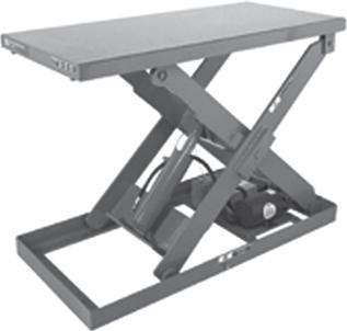
Figure 1.2illustrates an adjustable height platform that is driven by hydraulic cylinders.Although the entire device could be called a machine,the parts that take the power from the cylinders and drive the raising and lowering ofthe platform comprise the mechanism.
A mechanism can be considered rigid parts that are arranged and connected so that they produce the desired motion ofthe machine.The purpose ofthe mechanism in Figure 1.2is to lift the platform and any objects that are placed upon it. Synthesis is the process ofdeveloping a mechanism to satisfy a set ofperformance requirements for the machine. Analysis ensures that the mechanism will exhibit motion that will accomplish the set ofrequirements.
1.3KINEMATICS
Kinematics deals with the way things move.It is the study of the geometry ofmotion.Kinematic analysis involves determination ofposition,displacement,rotation,speed,velocity, and acceleration ofa mechanism.
To illustrate the importance ofsuch analysis,refer to the lift platform in Figure 1.2.Kinematic analysis provides insight into significant design questions,such as:
What is the significance ofthe length ofthe legs that support the platform?
Is it necessary for the support legs to cross and be connected at their midspan,or is it better to arrange the so that they cross closer to the platform?
How far must the cylinder extend to raise the platform 8 in.?
As a second step,dynamic force analysis ofthe platform could provide insight into another set ofimportant design questions:
What capacity (maximum force) is required ofthe hydraulic cylinder?
Is the platform free ofany tendency to tip over?
What cross-sectional size and material are required of the support legs so they don’t fail?
A majority ofmechanisms exhibit motion such that the parts move in parallel planes.For the device in Figure 1.2,two identical mechanisms are used on opposite sides ofthe platform for stability.However,the motion ofthese mechanisms is strictly in the vertical plane.Therefore,these mechanisms are called planar mechanisms because their motion is limited to two-dimensional space.Most commercially produced mechanisms are planar and are the focus ofthis book.
1.4MECHANISM TERMINOLOGY
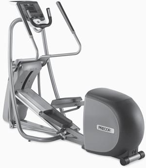
As stated,mechanisms consist ofconnected parts with the objective oftransferring motion and force from a power source to an output.A linkage is a mechanism where rigid parts are connected together to form a chain.One part is designated the frame because it serves as the frame ofreference for the motion ofall other parts.The frame is typically a part that exhibits no motion.A popular elliptical trainer exercise machine is shown in Figure 1.3.In this machine,two planar linkages are configured to operate out-of-phase to simulate walking motion,including the movement ofarms. Since the base sits on the ground and remains stationary during operation,the base is considered the frame.
Links are the individual parts ofthe mechanism.They are considered rigid bodies and are connected with other links to transmit motion and forces.Theoretically,a true rigid body does not change shape during motion.Although a true rigid body does not exist,mechanism links are designed to minimally deform and are considered rigid.The footrests and arm handles on the exercise machine comprise different links and,along with connecting links,are interconnected to produce constrained motion.
Elastic parts,such as springs,are not rigid and,therefore,are not considered links.They have no effect on the kinematics ofa mechanism and are usually ignored during
FIGURE 1.2 Adjustable height platform (Courtesy Advance Lifts).
FIGURE 1.3 Elliptical trainer exercise machine (photo from www.precor.com).
kinematic analysis.They do supply forces and must be included during the dynamic force portion ofanalysis.
A joint is a movable connection between links and allows relative motion between the links.The two primary joints, also called full joints,are the revolute and sliding joints.The revolute joint is also called a pin or hinge joint.It allows pure rotation between the two links that it connects.The sliding joint is also called a piston or prismatic joint.It allows linear sliding between the links that it connects.Figure 1.4illustrates these two primary joints.
A cam joint is shown in Figure 1.5a.It allows for both rotation and sliding between the two links that it connects. Because ofthe complex motion permitted,the cam connection is called a higher-order joint,also called halfjoint.A gear connection also allows rotation and sliding between two gears as their teeth mesh.This arrangement is shown in Figure 1.5b.The gear connection is also a higher-order joint.
A simple link is a rigid body that contains only two joints,which connect it to other links.Figure 1.6aillustrates a simple link.A crank is a simple link that is able to complete
Link 1
Link 2
(a) Cam joint(b) Gear joint
Link 2
Link 1
(a) Pin(b) Sliding
Link 1
Link 2
FIGURE 1.4 Primary joints:(a) Pin and (b) Sliding.
FIGURE 1.5 Higher-order joints:(a) Cam joint and (b) Gear joint.
(a) Simple link(b) Complex link
FIGURE 1.6 Links:(a) Simple link and (b) Complex link.
a full rotation about a fixed center.A rocker is a simple link that oscillates through an angle,reversing its direction at certain intervals.
A complex link is a rigid body that contains more than two joints.Figure 1.6billustrates a complex link.A rocker arm is a complex link,containing three joints,that is pivoted near its center.A bellcrank is similar to a rocker arm,but is bent in the center.The complex link shown in Figure 1.6bis a bellcrank.
A point ofinterest is a point on a link where the motion is ofspecial interest.The end ofthe windshield wiper,previously discussed,would be considered a point ofinterest. Once kinematic analysis is performed,the displacement, velocity,and accelerations ofthat point are determined.
The last general component ofa mechanism is the actuator.An actuator is the component that drives the mechanism.Common actuators include motors (electric and hydraulic),engines,cylinders (hydraulic and pneumatic),ball-screw motors,and solenoids.Manually operated machines utilize human motion,such as turning a crank,as the actuator.Actuators will be discussed further in Section 1.7.
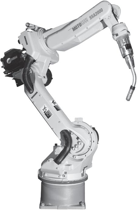
Linkages can be either open or closed chains.Each link in a closed-loop kinematic chain is connected to two or more other links.The lift in Figure 1.2and the elliptical trainer of Figure 1.3are closed-loop chains.An open-loop chain will have at least one link that is connected to only one other link.Common open-loop linkages are robotic arms as shown in Figure 1.7and other “reaching”machines such as backhoes and cranes.
1.5KINEMATIC DIAGRAMS
In analyzing the motion ofa machine,it is often difficult to visualize the movement ofthe components in a full assembly drawing.Figure 1.8shows a machine that is used to handle
1.7 Articulated robot (Courtesy ofMotoman Inc.).
parts on an assembly line.A motor produces rotational power, which drives a mechanism that moves the arms back and forth in a synchronous fashion.As can be seen in Figure 1.8,a pictorial ofthe entire machine becomes complex,and it is difficult to focus on the motion ofthe mechanism under consideration.
(This item omitted from WebBook edition)
1.8 Two-armed synchro loader (Courtesy PickOmatic Systems, Ferguson Machine Co.).
FIGURE
FIGURE
It is easier to represent the parts in skeleton form so that only the dimensions that influence the motion ofthe mechanism are shown.These “stripped-down”sketches of mechanisms are often referred to as kinematic diagrams.The purpose ofthese diagrams is similar to electrical circuit schematic or piping diagrams in that they represent variables that affect the primary function ofthe mechanism.
Table 1.1shows typical conventions used in creating kinematic diagrams. A kinematic diagram should be drawn to a scale proportional to the actual mechanism.For convenient reference,the links are numbered,starting with the frame as link number 1.To avoid confusion,the joints should be lettered.
Simple Link (with point ofinterest)
(continued)
TABLE1.1 Symbols Used in Kinematic Diagrams
Simple Link
Complex Link
Pin Joint
TABLE1.1 (Continued) Component
EXAMPLE PROBLEM 1.1
Figure 1.9shows a shear that is used to cut and trim electronic circuit board laminates.Draw a kinematic diagram.
FIGURE 1.9 Shear press for Example Problem 1.1.
SOLUTION: 1. Identify the Frame
The first step in constructing a kinematic diagram is to decide the part that will be designated as the frame. Themotion ofall other links will be determined relative to the frame.In some cases,its selection is obvious as the frame is firmly attached to the ground. In this problem,the large base that is bolted to the table is designated as the frame.The motion ofall other links is determined relative to the base.The base is numbered as link 1.
Slider Joint
Cam Joint
Gear Joint
2. Identify All Other Links
Careful observation reveals three other moving parts:
Link 2:Handle
Link 3:Cutting blade
Link 4:Bar that connects the cutter with the handle
3. Identify the Joints
Pin joints are used to connect link 1 to 2,link 2 to 3,and link 3 to 4.These joints are lettered A through C.In addition,the cutter slides up and down,along the base.This sliding joint connects link 4 to 1,and is lettered D
4. Identify Any Points ofInterest
Finally,the motion ofthe end ofthe handle is desired.This is designated as point ofinterest X.
5. Draw the Kinematic Diagram
The kinematic diagram is given in Figure 1.10.
EXAMPLE PROBLEM 1.2
1.10 Kinematic diagram for Example Problem 1.1.
Figure 1.11shows a pair ofvise grips.Draw a kinematic diagram.
FIGURE 1.11 Vise grips for Example Problem 1.2.
SOLUTION: 1. Identify the Frame
The first step is to decide the part that will be designated as the frame.In this problem,no parts are attached to the ground.Therefore,the selection ofthe frame is rather arbitrary.
The top handle is designated as the frame.The motion ofall other links is determined relative to the top handle.The top handle is numbered as link 1.
2. Identify All Other Links
Careful observation reveals three other moving parts:
Link 2:Bottom handle
Link 3:Bottom jaw
Link 4:Bar that connects the top and bottom handle
3. Identify the Joints
Four pin joints are used to connect these different links (link 1 to 2,2 to 3,3 to 4,and 4 to 1).These joints are lettered A through D
4. Identify Any Points ofInterest
The motion ofthe end ofthe bottom jaw is desired.This is designated as point ofinterest X .Finally,the motion ofthe end ofthe lower handle is also desired.This is designated as point ofinterest Y
FIGURE
5. Draw the Kinematic Diagram
The kinematic diagram is given in Figure 1.12.
1.6KINEMATIC INVERSION
Absolute motion is measured with respect to a stationary frame. Relative motion is measured for one point or link with respect to another link.As seen in the previous examples,the first step in drawing a kinematic diagram is selecting a member to serve as the frame.In some cases, the selection ofa frame is arbitrary,as in the vise grips from Example Problem 1.2.As different links are chosen as a frame,the relative motion ofthe links is not altered,but the absolute motion can be drastically different.For machines without a stationary link,relative motion is often the desired result ofkinematic analysis.
In Example Problem 1.2,an important result ofkinematic analysis is the distance that the handle must be moved in order to open the jaw.This is a question ofrelative position ofthe links:the handle and jaw.Because the relative motion ofthe links does not change with the selection ofa frame,the choice ofa frame link is often not important. Utilizing alternate links to serve as the fixed link is termed kinematic inversion.
1.7MOBILITY
An important property in mechanism analysis is the number of degrees offreedom ofthe linkage.The degree offreedom is the number ofindependent inputs required to precisely position all links ofthe mechanism with respect to the ground.It can also be defined as the number ofactuators needed to operate the mechanism.A mechanism actuator could be manually moving one link to another position,connecting a motor to the shaft ofone link,or pushing a piston ofa hydraulic cylinder.
The number ofdegrees offreedom ofa mechanism is also called the mobility, and it is given the symbol .WhenM
the configuration ofa mechanism is completely defined by positioning one link,that system has one degree offreedom. Most commercially produced mechanisms have one degree offreedom.In constrast,robotic arms can have three,or more,degrees offreedom.
1.7.1Gruebler’s Equation
Degrees offreedom for planar linkages joined with common joints can be calculated through Gruebler’s equation:
M = degrees of freedom = 3(
where:
n = total number of links in the mechanism
jp = total number of primary joints (pins or sliding joints)
j h total number ofhigher-order joints (cam or gear joints)
As mentioned,most linkages used in machines have one degree offreedom.A single degree-of-freedom linkage is shown in Figure 1.13a.
Linkages with zero,or negative,degrees offreedom are termed locked mechanisms. These mechanisms are unable to move and form a structure.A truss is a structure composed ofsimple links and connected with pin joints and zero degrees offreedom.A locked mechanism is shown in Figure 1.13b.
Linkages with multiple degrees offreedom need more than one driver to precisely operate them.Common multi-degree-of-freedom mechanisms are open-loop kinematic chains used for reaching and positioning,such as robotic arms and backhoes.In general,multi-degree-offreedom linkages offer greater ability to precisely position a link.A multi-degree-of-freedom mechanism is shown in Figure 1.13c.
FIGURE 1.13 Mechanisms and structures with varying
FIGURE 1.12 Kinematic diagram for Example Problem 1.2.
EXAMPLE PROBLEM 1.3
Figure 1.14shows a toggle clamp.Draw a kinematic diagram,using the clamping jaw and the handle as points of interest.Also compute the degrees offreedom for the clamp.
SOLUTION:
1. Identify the Frame
The component that is bolted to the table is designated as the frame.The motion ofall other links is determined relative to this frame.The frame is numbered as link 1.
2. Identify All Other Links
Careful observation reveals three other moving parts:
Link 2:Handle
Link 3:Arm that serves as the clamping jaw
Link 4:Bar that connects the clamping arm and handle
3. Identify the Joints
Four pin joints are used to connect these different links (link 1 to 2,2 to 3,3 to 4,and 4 to 1).These joints are lettered A through D
4. Identify Any Points ofInterest
The motion ofthe clamping jaw is desired.This is designated as point ofinterest X.Finally,the motion ofthe end ofthe handle is also desired.This is designated as point ofinterest Y
5. Draw the Kinematic Diagram
The kinematic diagram is detailed in Figure 1.15.
6. Calculate Mobility
Having four links and four pin joints,
FIGURE 1.14 Toggle clamp for Example Problem 1.3.
FIGURE 1.15 Kinematic diagram for Example Problem 1.3.
SOLUTION:
With one degree offreedom,the clamp mechanism is constrained.Moving only one link,the handle,precisely positions all other links in the clamp.
EXAMPLE PROBLEM 1.4
Figure 1.16shows a beverage can crusher used to reduce the size ofcans for easier storage prior to recycling.Draw a kinematic diagram,using the end ofthe handle as a point ofinterest.Also compute the degrees offreedom for the device.
FIGURE 1.16 Can crusher for Example Problem 1.4. and
1. Identify the Frame
The back portion ofthe device serves as a base and can be attached to a wall.This component is designated asthe frame.The motion ofall other links is determined relative to this frame.The frame is numbered as link 1.
2. Identify All Other Links
Careful observation shows a planar mechanism with three other moving parts:
Link 2:Handle
Link 3:Block that serves as the crushing surface
Link 4:Bar that connects the crushing block and handle
3. Identify the Joints
Three pin joints are used to connect these different parts.One pin connects the handle to the base.This joint is labeled as A.A second pin is used to connect link 4 to the handle.This joint is labeled B.The third pin connects the crushing block and link 4.This joint is labeled C
The crushing block slides vertically during operation;therefore,a sliding joint connects the crushing block to the base.This joint is labeled D
4. Identify Any Points ofInterest
The motion ofthe handle end is desired.This is designated as point ofinterest X
5. Draw the Kinematic Diagram
The kinematic diagram is given in Figure 1.17.
FIGURE 1.17
Kinematic diagram for Example Problem 1.4.
6. Calculate Mobility
It was determined that there are four links in this mechanism.There are also three pin joints and one slider joint. Therefore, and
With one degree offreedom,the can crusher mechanism is constrained.Moving only one link,the handle,precisely positions all other links and crushes a beverage can placed under the crushing block.
EXAMPLE PROBLEM 1.5
Figure 1.18shows another device that can be used to shear material.Draw a kinematic diagram,using the end ofthe handle and the cutting edge as points ofinterest.Also,compute the degrees offreedom for the shear press.
SOLUTION:
1. Identify the Frame
The base is bolted to a working surface and can be designated as the frame.The motion ofall other links is determined relative to this frame.The frame is numbered as link 1.
2. Identify All Other Links
Careful observation reveals two other moving parts:
Link 2:Gear/handle
Link 3:Cutting lever
3. Identify the Joints
Two pin joints are used to connect these different parts.One pin connects the cutting lever to the frame. This joint is labeled as A .A second pin is used to connect the gear/handle to the cutting lever.This joint is labeled B
The gear/handle is also connected to the frame with a gear joint.This higher-order joint is labeled C
4. Identify Any Points ofInterest
The motion ofthe handle end is desired and is designated as point ofinterest X.The motion ofthe cutting surface is also desired and is designated as point ofinterest Y
5. Draw the Kinematic Diagram
The kinematic diagram is given in Figure 1.19.
FIGURE 1.18 Shear press for Example Problem 1.5.
6. Calculate Mobility
To calculate the mobility,it was determined that there are three links in this mechanism.There are also two pin joints and one gear joint.Therefore, and With one degree offreedom,the shear press mechanism is constrained.Moving only one link,the handle, precisely positions all other links and brings the cutting edge onto the work piece.
1.7.2Actuators and Drivers
In order to operate a mechanism,an actuator,or driver device,is required to provide the input motion and energy. To precisely operate a mechanism,one driver is required for each degree offreedom exhibited.Many different actuators are used in industrial and commercial machines and mechanisms.Some ofthe more common ones are given below:
Electric motors (AC) provide the least expensive way to generate continuous rotary motion.However, they are limited to a few standard speeds that are a function ofthe electric line frequency.In North America the line frequency is 60 Hz,which corresponds to achievable speeds of3600,1800,900,720, and 600 rpm.Single-phase motors are used in residential applications and are available from 1/50 to 2hp.Three-phase motors are more efficient,but mostly limited to industrial applications because they require three-phase power service.They are available from 1/4 to 500 hp.
Electric motors (DC) also produce continuous rotary motion.The speed and direction ofthe motion can be readily altered,but they require power from a generator or a battery.DC motors can achieve extremely high speeds––up to 30,000 rpm.These motors are most often used in vehicles,cordless devices,or in applications where multiple speeds and directional control are required,such as a sewing machine.
Engines also generate continuous rotary motion.The speed ofan engine can be throttled within a range ofapproximately 1000 to 8000 rpm.They are a popular and highly portable driver for high-power applications.Because they rely on the combustion offuel,engines are used to drive machines that operate outdoors.
Servomotors are motors that are coupled with a controller to produce a programmed motion or hold a fixed position.The controller requires sensors on the link being moved to provide feedback information on its position,velocity,and acceleration.These motors have lower power capacity than nonservomotors and are significantly more expensive,but they can be used for machines demanding precisely guided motion, such as robots.
Air or hydraulic motors also produce continuous rotary motion and are similar to electric motors,but have more limited applications.This is due to the need for compressed air or a hydraulic source.These drive devices are mostly used within machines,such as construction equipment and aircraft,where highpressure hydraulic fluid is available.
Hydraulic or pneumatic cylinders are common components used to drive a mechanism with a limited linear stroke.Figure 1.20aillustrates a hydraulic cylinder.Figure 1.20bshows the common kinematic representation for the cylinder unit.
FIGURE 1.19 Kinematic diagram for Example Problem 1.5.
Pin joint
Cylinder (a)(b)
Pin joint Link A (cylinder)
1.20 Hydraulic cylinder.
The cylinder unit contains a rod and piston assembly that slides relative to a cylinder.For kinematic purposes,these are two links (piston/rod and cylinder), connected with a sliding joint.In addition,the cylinder and rod end usually have provisions for pin joints.
Screw actuators also produce a limited linear stroke. These actuators consist ofa motor,rotating a screw.A mating nut provides the linear motion.Screw actuators can be accurately controlled and can directly replace cylinders.However,they are considerably
EXAMPLE PROBLEM 1.6
Sliding joint
Link B (piston/rod)
more expensive than cylinders ifair or hydraulic sources are available.Similar to cylinders,screw actuators also have provisions for pin joints at the two ends.Therefore,the kinematic diagram is identical to Figure 1.20b.
Manual,or hand-operated,mechanisms comprise a large number ofmachines,or hand tools.The motions expected from human “actuators”can be quite complex.However,ifthe expected motions are repetitive, caution should be taken against possible fatigue and stain injuries.
Figure 1.21shows an outrigger foot to stabilize a utility truck.Draw a kinematic diagram,using the bottom ofthe stabilizing foot as a point ofinterest.Also compute the degrees offreedom.
1.21 Outrigger for Example Problem 1.6.
SOLUTION: 1. Identify the Frame
During operation ofthe outriggers,the utility truck is stationary.Therefore,the truck is designated as the frame.The motion ofall other links is determined relative to the truck.The frame is numbered as link 1.
2. Identify All Other Links
Careful observation reveals three other moving parts:
Link 2:Outrigger leg
Link 3:Cylinder
Link 4:Piston/rod
3. Identify the Joints
Three pin joints are used to connect these different parts.One connects the outrigger leg with the truck frame. This is labeled as joint A.Another connects the outrigger leg with the cylinder rod and is labeled as joint B.The last pin joint connects the cylinder to the truck frame and is labeled as joint C
One sliding joint is present in the cylinder unit.This connects the piston/rod with the cylinder.It is labeled as joint D.
Rod Piston
FIGURE
FIGURE
4. Identify Any Points ofInterest
The stabilizer foot is part oflink 2,and a point ofinterest located on the bottom ofthe foot is labeled as point of interest X
5. Draw the Kinematic Diagram
The resulting kinematic diagram is given in Figure 1.22.
FIGURE 1.22 Kinematic diagram for Example Problem 1.6.
6. Calculate Mobility
To calculate the mobility,it was determined that there are four links in this mechanism,as well as three pin joints and one slider joint.Therefore, and
With one degree offreedom,the outrigger mechanism is constrained.Moving only one link,the piston, precisely positions all other links in the outrigger,placing the stabilizing foot on the ground.
1.8COMMONLY USED LINKS AND JOINTS
1.8.1Eccentric Crank
On many mechanisms,the required length ofa crank is so short that it is not feasible to fit suitably sized bearings at the two pin joints.A common solution is to design the link as an eccentric crankshaft,as shown in Figure 1.23a.This is the design used in most engines and compressors.
The pin,on the moving end ofthe link,is enlarged such that it contains the entire link.The outside circumference ofthe circular lobe on the crankshaft becomes the moving pin joint,as shown in Figure 1.23b.The location of the fixed bearing,or bearings,is offset from the eccentric lobe.This eccentricity ofthe crankshaft,,is the effective length ofthe crank.Figure 1.23cillustrates a kinematic e
model ofthe eccentric crank.The advantage ofthe eccentric crank is the large surface area ofthe moving pin,which reduces wear.
1.8.2Pin-in-a-Slot Joint
A common connection between links is a pin-in-a-slot joint,as shown in Figure 1.24a.This is a higher-order joint because it permits the two links to rotate and slide relative to each other.To simplify the kinematic analysis,primary joints can be used to model this higher-order joint.The pin-in-a-slot joint becomes a combination ofa pin joint and a sliding joint,as in Figure 1.24b.Note that this involves adding an extra link to the mechanism.In both cases,the relative motion between the links is the same. However,using a kinematic model with primary joints facilitates the analysis.
1.23
FIGURE
Eccentric crank.
(b) Pin-in-a-slot model (a) Actual pin-in-a-slot joint
1.24 Pin-in-a-slot joint.
1.8.3Screw Joint
A screw joint,as shown in Figure 1.25a,is another common connection between links.Screw mechanisms are discussed in detail in Chapter 12.To start with,a screw joint permits two relative,but dependent,motions between the links being joined.A specific rotation ofone link will cause an associated relative translation between the two links.For example, turning the screw one revolution may move the nut along the screw threads a distance of0.1 in.Thus,only one independent motion is introduced.
(b) Screw modeled as a slider (a) Actual screw joint
1.25 Screw joint.
A screw joint is typically modeled with a sliding joint,as shown in Figure 1.25b.It must be understood that out-ofplane rotation occurs.However,only the relative translation between the screw and nut is considered in planar kinematic analysis.
An actuator,such as a hand crank,typically produces the out-of-plane rotation.A certain amount ofrotation will cause a corresponding relative translation between the links being joined by the screw joint.This relative translation is used as the “driver”in subsequent kinematic analyses.
EXAMPLE PROBLEM 1.7
Figure 1.26presents a lift table used to adjust the working height ofdifferent objects.Draw a kinematic diagram and compute the degrees offreedom.
1.26 Lift table for Example Problem 1.7.
SOLUTION: 1. Identify the Frame
The bottom base plate rests on a fixed surface.Thus,the base plate will be designated as the frame.The bearing at the bottom right ofFigure 1.26is bolted to the base plate.Likewise,the two bearings that support the screw on the left are bolted to the base plate.
From the discussion in the previous section,the out-of-plane rotation ofthe screw will not be considered. Only the relative translation ofthe nut will be included in the kinematic model.Therefore,the screw will also be considered as part ofthe frame.The motion ofall other links will be determined relative to this bottom base plate,which will be numbered as link 1.
FIGURE
FIGURE
FIGURE
1.9SPECIAL
2. Identify All Other Links
Careful observation reveals five other moving parts:
Link 2:Nut
Link 3:Support arm that ties the nut to the table
Link 4:Support arm that ties the fixed bearing to the slot in the table
Link 5:Table
Link 6:Extra link used to model the pin in slot joint with separate pin and slider joints
3. Identify the Joints
A sliding joint is used to model the motion between the screw and the nut.A pin joint,designated as point A, connects the nut to the support arm identified as link 3.A pin joint,designated as point B,connects the two support arms––link 3 and link 4.Another pin joint,designated as point C ,connects link 3 to link 6.A sliding joint joins link 6 to the table,link 5.A pin,designated as point D,connects the table to the support arm,link 3.Lastly, a pin joint,designated as point E,is used to connect the base to the support arm,link 4.
4. Draw the Kinematic Diagram
The kinematic diagram is given in Figure 1.27.
FIGURE 1.27 Kinematic diagram for Example Problem 1.7.
5. Calculate Mobility
To calculate the mobility,it was determined that there are six links in this mechanism.There are also five pin joints and two slider joints.Therefore and
= 6 jp = (5 pins + 2 sliders) = 7 j h = 0
With one degree offreedom,the lift table has constrained motion.Moving one link,the handle that rotates the screw,will precisely position all other links in the device,raising or lowering the table. M = 3(n - 1) - 2 j p - j h = 3(6 - 1) - 2(7) - 0 = 15 - 14 = 1
CASES OF THE MOBILITY EQUATION
Mobility is an extremely important property ofa mechanism.Among other facets,it gives insight into the number of actuators required to operate a mechanism.However,to obtain correct results,special care must be taken in using the Gruebler’s equation.Some special conditions are presented next.
1.9.1Coincident
Joints
Some mechanisms have three links that are all connected at a common pin joint,as shown in Figure 1.28.This situation brings some confusion to kinematic modeling.Physically,
(a) Three rotating links
(b) Two rotating and one sliding link
FIGURE 1.28 Three links connected at a common pin joint.
one pin may be used to connect all three links.However,by definition,a pin joint connects two links.
For kinematic analysis,this configuration must be mathematically modeled as two separate joints.One joint will
connect the first and second links.The second joint will then connect the second and third links.Therefore,when three links
EXAMPLE PROBLEM 1.8
come together at a common pin,the joint must be modeled as two pins.This scenario is illustrated in Example Problem 1.8.
SOLUTION:
Figure 1.29shows a mechanical press used to exert large forces to insert a small part into a larger one. Draw a kinematic diagram,using the end ofthe handle as a point ofinterest.Also compute the degrees of freedom.
FIGURE 1.29 Mechanical press for Example Problem 1.8.
1. Identify the Frame
The bottom base for the mechanical press sits on a workbench and remains stationary during operation. Therefore,this bottom base is designated as the frame.The motion ofall other links is determined relative to the bottom base.The frame is numbered as link 1.
2. Identify All Other Links
Careful observation reveals five other moving parts:
Link 2:Handle
Link 3:Arm that connects the handle to the other arms
Link 4:Arm that connects the base to the other arms
Link 5:Press head
Link 6:Arm that connects the head to the other arms
3. Identify the Joints
Pin joints are used to connect the several different parts.One connects the handle to the base and is labeled as joint A .Another connects link 3 to the handle and is labeled as joint B .Another connects link 4 to the base and is labeled as C .Another connects link 6 to the press head and is labeled as D .
It appears that a pin is used to connect the three arms—links 3,4,and 6—together.Because three separate links are joined at a common point,this must be modeled as two separate joints.They are labeled as E and F
A sliding joint connects the press head with the base.This joint is labeled as G
4. Identify Any Points ofInterest
Motion ofthe end ofthe handle is desired and is labeled as point ofinterest X
5. Draw the Kinematic Diagram
The kinematic diagram is given in Figure 1.30.
6. Calculate Mobility
To calculate the mobility,it was determined that there are six links in this mechanism,as well as six pin joints and one slider joint.Therefore,
FIGURE 1.30 Kinematic diagram for Example Problem 1.8.
1.9.2Exceptions to the Gruebler’s Equation
Another special mobility situation must be mentioned. Because the Gruebler’s equation does not account for link geometry,in rare instances it can lead to misleading results. One such instance is shown in Figure 1.31.
FIGURE 1.31 Mechanism that violates the Gruebler’s equation. and With one degree offreedom,the mechanical press mechanism is constrained.Moving only one link, the handle,precisely positions all other links in the press,sliding the press head onto the work piece.
redundant,and because it is identical in length to the other two links attached to the frame,it does not alter the action of the linkage.
There are other examples ofmechanisms that violate the Gruebler’s equation because ofunique geometry.A designer must be aware that the mobility equation can,at times,lead to inconsistencies.
1.9.3Idle
Degrees ofFreedom
In some mechanisms,links exhibit motion which does not influence the input and output relationship ofthe mechanism.These idle degrees offreedom present another situation where Gruebler’s equation gives misleading results. Anexample is a cam with a roller follower as shown in Figure1.32.Gruebler’s equation specifies two degrees of freedom (4links,3 pins,1 higher-order joint).With an actuated cam rotation,the pivoted link oscillates while the roller follower rotates about its center.Yet,only the motion ofthe pivoted link serves as the output ofthe mechanism.
Notice that this linkage contains five links and six pin joints.Using Gruebler’s equation,this linkage has zero degrees offreedom.Ofcourse,this suggests that the mechanism is locked.However,ifall pivoted links were the same size,and the distance between the joints on the frame and coupler were identical,this mechanism would be capable of motion,with one degree offreedom.The center link is
The roller rotation is an idle degree offreedom and not intended to affect the output motion ofthe mechanism. Itis a design feature which reduces friction and wear on the surface ofthe cam.While Gruebler’s equation specifies that a cam mechanism with a roller follower has a mobility of two,the designer is typically only interested in a single degree offreedom.Several other mechanisms contain similar idle degrees offreedom.
1.32 A cam with a roller follower.
FIGURE
1.10THE FOUR-BAR MECHANISM
The simplest and most common linkage is the four-bar linkage.It is a combination offour links,one being designated as the frame and connected by four pin joints.
Because it is encountered so often,further exploration is in order.
The mechanism for an automotive rear-window wiper system is shown in Figure 1.33a.The kinematic diagram is shown in Figure 1.33b.Notice that this is a four-bar mechanism
1.33 Rear-window wiper mechanism.
because it is comprised offour links connected by four pin joints and one link is unable to move.
The mobility ofa four-bar mechanism consists ofthe following:
n = 4, jp = 4 pins, jh = 0
and Because the four-bar mechanism has one degree of freedom,it is constrained or fully operated with one driver. The wiper system in Figure 1.33is activated by a single DC electric motor.
M = 3(n - 1) - 2jp - jh = 3(4 - 1) - 2(4) - 0 = 1
Ofcourse,the link that is unable to move is referred to as the frame.Typically,the pivoted link that is connected to the driver or power source is called the input link .The other pivoted link that is attached to the frame is designated the output link or follower .The coupler or connecting arm “couples”the motion ofthe input link to the output link.
1.10.1Grashof’s Criterion
The following nomenclature is used to describe the length of the four links.
s = length of the shortest link
l = length of the longest link
p = length of one of the intermediate length links
q = length of the other intermediate length links
Grashof’s theorem states that a four-bar mechanism has at least one revolving link if:
s + l … p + q
Conversely,the three nonfixed links will merely rock if:
s + l 7 p + q
All four-bar mechanisms fall into one ofthe five categories listed in Table 1.2.
FIGURE
TABLE1.2 Categories ofFour-Bar Mechanisms
1.34 Categories offour-bar mechanisms.
The different categories are illustrated in Figure 1.34 and described in the following sections.
1.10.2Double
Crank
A double crank,or crank-crank,is shown in Figure 1.34a.As specified in the criteria ofCase 1 ofTable 1.2,it has the shortest link ofthe four-bar mechanism configured as the frame.Ifone ofthe pivoted links is rotated continuously,the other pivoted link will also rotate continuously.Thus,the two pivoted links,2 and 4,are both able to rotate through a full revolution.The double crank mechanism is also called a drag link mechanism.
1.10.3Crank-Rocker
A crank-rocker is shown in Figure 1.34b.As specified in the criteria ofCase 2 ofTable 1.2,it has the shortest link ofthe four-bar mechanism configured adjacent to the frame.Ifthis shortest link is continuously rotated,the output link will oscillate between limits.Thus,the shortest link is called the crank,and the output link is called the rocker.The wiper system in Figure 1.33is designed to be a crank-rocker.As the motor continuously rotates the input link,the output link oscillates, or “rocks.”The wiper arm and blade are firmly attached to the output link,oscillating the wiper across a windshield.
1.10.4Double Rocker
The double rocker,or rocker-rocker,is shown in Figure 1.34c.As specified in the criteria ofCase 3 ofTable 1.2,it
EXAMPLE PROBLEM 1.9
has the link opposite the shortest link ofthe four-bar mechanism configured as the frame.In this configuration, neither link connected to the frame will be able to complete a full revolution.Thus,both input and output links are constrained to oscillate between limits,and are called rockers. However,the coupler is able to complete a full revolution.
1.10.5Change Point Mechanism
A change point mechanism is shown in Figure 1.34d.As specified in the criteria ofCase 4 ofTable 1.2,the sum oftwo sides is the same as the sum ofthe other two.Having this equality,the change point mechanism can be positioned such that all the links become collinear.The most familiar type ofchange point mechanism is a parallelogram linkage. The frame and coupler are the same length,and so are the two pivoting links.Thus,the four links will overlap each other.In that collinear configuration,the motion becomes indeterminate.The motion may remain in a parallelogram arrangement,or cross into an antiparallelogram,or butterfly,arrangement.For this reason,the change point is called a singularity configuration.
1.10.6Triple Rocker
A triple rocker linkage is shown in Figure 1.34e.Exhibiting the criteria in Case 5 ofTable 1.2,the triple rocker has no links that are able to complete a full revolution.Thus,all three moving links rock.
A nosewheel assembly for a small aircraft is shown in Figure 1.35.Classify the motion ofthis four-bar mechanism based on the configuration ofthe links.
(a) Double crank
(c) Double rocker
(d) Change point
(e) Triple rocker
(b) Crank-rocker
FIGURE
SOLUTION:
1. Distinguish the Links Based on Length
In an analysis that focuses on the landing gear,the motion ofthe wheel assembly would be determined relative to the body ofthe aircraft.Therefore,the aircraft body will be designated as the frame.Figure 1.36shows the kinematic diagram for the wheel assembly,numbering and labeling the links.The tip ofthe wheel was designated as point ofinterest X
1.36 Kinematic diagram for Example Problem 1.9.
The lengths ofthe links are:
s = 12 in.; l = 32 in.; p = 30 in.; q = 26 in.
2. Compare to Criteria
The shortest link is a side,or adjacent to the frame.According to the criteria in Table 1.2,this mechanism can be either a crank-rocker,change point,or a triple rocker.The criteria for the different categories offour-bar mechanisms should be reviewed.
3. Check the Crank-Rocker (Case 2) Criteria Is:
s + l 6 p + q
(12 + 32) 6 (30 + 26)
44 6 56 : {yes}
Because the criteria for a crank-rocker are valid,the nosewheel assembly is a crank-rocker mechanism.
FIGURE 1.35 Nosewheel assembly for Example Problem 1.9.
FIGURE