Structural Analysis 8th Edition Solutions Manual Russell C. Hibbeler
Visit to download the full and correct content document: https://ebookmass.com/product/structural-analysis-8th-edition-solutions-manual-russe ll-c-hibbeler/
More products digital (pdf, epub, mobi) instant download maybe you interests ...
Structural analysis 7th ed Edition Russell C. Hibbeler
https://ebookmass.com/product/structural-analysis-7th-ed-editionrussell-c-hibbeler/
Engineering Mechanics: Statics (Solutions Manual
Chapters 1 - 9) 14th Edition Russell C. Hibbeler
https://ebookmass.com/product/engineering-mechanics-staticssolutions-manual-chapters-1-9-14th-edition-russell-c-hibbeler/
Structural Analysis in SI Units 10th Edition Hibbeler
https://ebookmass.com/product/structural-analysis-in-siunits-10th-edition-hibbeler/
Fluid Mechanics (2nd ed.) Global Edition Russell C. Hibbeler
https://ebookmass.com/product/fluid-mechanics-2nd-ed-globaledition-russell-c-hibbeler/
Engineering Mechanics: Statics, SI Units, 15th Edition
Russell Hibbeler
https://ebookmass.com/product/engineering-mechanics-statics-siunits-15th-edition-russell-hibbeler/
Engineering Mechanics: Dynamics, SI Units 15th Edition
Russell Hibbeler
https://ebookmass.com/product/engineering-mechanics-dynamics-siunits-15th-edition-russell-hibbeler/
Fundamentals of Structural Analysis Solution Manual 5th edition Kenneth M. Leet
https://ebookmass.com/product/fundamentals-of-structuralanalysis-solution-manual-5th-edition-kenneth-m-leet/
Mecanica de Materiales (Spanish Edition) R. C. Hibbeler
https://ebookmass.com/product/mecanica-de-materiales-spanishedition-r-c-hibbeler/

Student Solutions Manual, Chapters 10-17 for Stewart’s
Multivariable Calculus, 8th (James Stewart Calculus) 8th
https://ebookmass.com/product/student-solutions-manualchapters-10-17-for-stewarts-multivariable-calculus-8th-jamesstewart-calculus-8th/
1–1. The floor of a heavy storage warehouse building is made of 6-in.-thick stone concrete.If the floor is a slab having a length of 15 ft and width of 10 ft,determine the resultant force caused by the dead load and the live load.
From Table 1–3
DL = [12 lb ft2 in.(6 in.)] (15 ft)(10 ft) = 10,800 lb
From Table 1–4
LL = (250 lb ft2)(15 ft)(10 ft) = 37,500 lb
Total Load
F = 48,300 lb = 48.3 k
1–2. The floor of the office building is made of 4-in.-thick lightweight concrete.If the office floor is a slab having a length of 20 ft and width of 15 ft,determine the resultant force caused by the dead load and the live load.
From Table 1–3
DL = [8 lb ft2 in.(4 in.)] (20 ft)(15 ft) = 9600 lb
From Table 1–4
LL = (50 lb ft2)(20 ft)(15 ft) = 15,000 lb
Total Load
F = 24,600 lb = 24.6 k
1–3. The T-beam is made from concrete having a specific weight of 150 lb ft3.Determine the dead load per foot length of beam.Neglect the weight of the steel reinforcement. w = (150 lb ft3) [(40 in.)(8 in.) + (18 in.) (10 in.)]
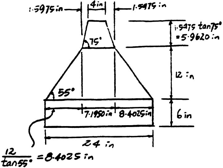
*1–4. The “New Jersey”barrier is commonly used during highway construction.Determine its weight per foot of length if it is made from plain stone concrete.
Cross-sectional area = 6(24) + (24 + 7.1950)(12) + (4 + 7.1950)(5.9620) = 364.54 in2
Use Table 1–2.
w = 144lb ft3 (364.54 in2) = 365lb ft
a 1 ft2 144 in2 b a 1 2 b a 1 2 b
1–5. The floor of a light storage warehouse is made of 150-mm-thick lightweight plain concrete.If the floor is a slab having a length of 7 m and width of 3 m,determine the resultant force caused by the dead load and the live load.
From Table 1–3
DL = [0.015 kN m2 mm(150 mm)] (7 m) (3 m) = 47.25 kN
From Table 1–4
LL = (6.00 kN m2) (7 m) (3 m) = 126 kN
Total Load
F = 126 kN + 47.25 kN = 173 kN
material is protected under all copyright laws as they currently
No portion of this material may be reproduced,in any form or by any means,without permission in writing from the publisher.
1–6. The prestressed concrete girder is made from plain stone concrete and four -in.cold form steel reinforcing rods.Determine the dead weight of the girder per foot of its length. 3 4
Area of concrete = 48(6) + 4(14 + 8)(4) - 4( ) = 462.23 in2
Area of steel = 4( ) = 1.767 in2
From Table 1–2, w = (144 lb ft3)(462.23 in2) + 492 lb ft3(1.767 in2) = 468
1–7. The wall is 2.5 m high and consists of 51 mm 102 mm studs plastered on one side.On the other side is 13mm fiberboard,and 102 mm clay brick.Determine the average load in kN m of length of wall that the wall exerts on the floor.
Use Table 1–3.
For studs
Weight = 0.57 kN m2 (2.5 m) = 1.425 kN m
For fiberboard
Weight = 0.04 kN m2 (2.5 m) = 0.1 kN m
For clay brick
Weight = 1.87 kN m2 (2.5 m) = 4.675 kN m
Total weight = 6.20 kN m Ans.
No portion of this material may be reproduced,in any form or by any means,without permission in writing from the publisher.
*1–8. A building wall consists of exterior stud walls with brick veneer and 13mm fiberboard on one side.If the wall is 4 m high,determine the load in kN m that it exerts on the floor.
For stud wall with brick veneer.
w = (2.30 kN m2)(4 m) = 9.20 kN m
For Fiber board
w = (0.04 kN m2)(4 m) = 0.16 kN m
Total weight = 9.2 + 0.16 = 9.36 kN m
1–9. The interior wall of a building is made from 2 4 wood studs,plastered on two sides.If the wall is 12 ft high, determine the load in lb ftof length of wall that it exerts on the floor.
From Table 1–3
w = (20 lb ft2)(12 ft) = 240 lb ft
1–10. The second floor of a light manufacturing building is constructed from a 5-in.-thick stone concrete slab with an added 4-in.cinder concrete fill as shown.If the suspended ceiling of the first floor consists of metal lath and gypsum plaster,determine the dead load for design in pounds per square foot of floor area.
From Table 1–3, 5-in.concrete slab = (12)(5) = 60.0
4-in.cinder fill = (9)(4) = 36.0 metal lath & plaster = 10.0
Total dead load = 106.0 lb ft2
No portion of this material may be reproduced,in any form or by any means,without permission in writing from the publisher.
1–11. A four-story office building has interior columns spaced 30 ft apart in two perpendicular directions.If the flat-roof live loading is estimated to be 30 lb ft2,determine the reduced live load supported by a typical interior column located at ground level.
Floor load:
L o = 50 psf
At = (30)(30) = 900 ft2 7 400 ft2
L = L o(0.25 + )
L = 50(0.25 + ) = 25 psf
% reduction == 50% 7 40% (OK)
F s = 3[(25 psf)(30 ft)(30 ft)] + 30 psf(30 ft)(30 ft) = 94.5 k Ans. 25 50 15 24(900) 15 2KLLAT
*1–12. A two-story light storage warehouse has interior columns that are spaced 12 ft apart in two perpendicular directions.If the live loading on the roof is estimated to be 25 lb ft2,determine the reduced live load supported by a typical interior column at (a) the ground-floor level,and (b) the second-floor level.
At = (12)(12) = 144 ft2
FR = (25)(144) = 3600 lb = 3.6 k
Since At = 4(144) ft2 7 400 ft2
L = 12.5(0.25 + ) = 109.375 lb ft2
(a) For ground floor column
L = 109 psf 7 0.5 L o = 62.5 psfOK
FF = (109.375)(144) = 15.75 k
F = FF + FR = 15.75 k + 3.6 k = 19.4 k Ans.
(b) For second floor column
F = FR = 3.60 k Ans. 15 2(4)(144)
1–13. The office building has interior columns spaced 5 m apart in perpendicular directions.Determine the reduced live load supported by a typical interior column located on the first floor under the offices.
From Table 1–4
L o = 2.40 kN m2
AT = (5 m)(5 m) = 25 m2
KLL = 4
L = L o(0.25 + )
L = 2.40(0.25 + )
L = 1.70 kN m2
1.70 kN m2 7 0.4 L o = 0.96 kN m2 OK 4.57 24(25) 4.57 2KLLAT
Ans.
1–14. A two-story hotel has interior columns for the rooms that are spaced 6 m apart in two perpendicular directions.Determine the reduced live load supported by a typical interior column on the first floor under the public rooms.
Table 1–4
L o = 4.79 kN m2
AT = (6 m)(6 m) = 36 m2
KLL = 4
L = L o(0.25 + )
L = 4.79(0.25 + )
L = 3.02kN m2
3.02 kN m2 7 0.4 L o = 1.916 kN m2 OK 4.57 24(36) 4.57 2KLL AT
Ans.
1–15. Wind blows on the side of a fully enclosed hospital located on open flat terrain in Arizona.Determine the external pressure acting over the windward wall,which has a height of 30 ft.The roof is flat.
V = 120 mi h
Kzt = 1.0
Kd = 1.0
qz = 0.00256 K zKztKdV2 = 0.00256 K z (1.0)(1.0)(120)2 = 36.86 K z
From Table 1–5, zKz qz
0–150.8531.33
200.9033.18
250.9434.65
300.9836.13
Thus, p = qG Cp – qh (G C pi) = q (0.85)(0.8) - 36.13 (; 0.18)
= 0.68q < 6.503
p0–15 = 0.68(31.33) < 6.503 = 14.8 psf or 27.8 psf
p20 = 0.68(33.18) < 6.503 = 16.1 psf or 29.1 psf
p25 = 0.68(34.65) < 6.503 = 17.1 psf or 30.1 psf
p30 = 0.68(36.13) < 6.503 = 18.1 psf or 31.1 psf
Ans.
Ans.
Ans.
Ans.
*1–16. Wind blows on the side of the fully enclosed hospital located on open flat terrain in Arizona.Determine the external pressure acting on the leeward wall,which has a length of 200 ft and a height of 30 ft.
V = 120 mi h
Kzt = 1.0
Kd = 1.0
qh = 0.00256 K zKztKdV2
= 0.00256 K z(1.0)(1.0)(120)2 = 36.86 K z
1–16.Continued
From Table 1–5,for z = h = 30 ft, K z = 0.98
qh = 36.86(0.98) = 36.13
From the text
200 200 Lo B
== 1 so that C p =- 0.5
p = q GCp - qh(GC p2)
p = 36.13(0.85)(-0.5) - 36.13(; 0.18)
p =- 21.9 psf or - 8.85 psf Ans.
1–17. A closed storage building is located on open flat terrain in central Ohio.If the side wall of the building is 20ft high,determine the external wind pressure acting on the windward and leeward walls.Each wall is 60 ft long. Assume the roof is essentially flat.
V = 105 mi h
Kzt = 1.0
Kd = 1.0
q = 0.00256 K zKztKdV2 = 0.00256 K z(1.0)(1.0) (105)2 = 28.22 K z
From Table 1–5
zKz qz 0–150.8523.99 200.9025.40
Thus,for windward wall
p = qGCp – qh(GC pi )
= q(0.85)(0.8) – 25.40(; 0.18)
= 0.68 q < 4.572
p0 – 15 = 0.68 (23.99) < 4.572 = 11.7 psf or 20.9 psf
p20 = 0.68 (25.40) < 4.572 = 12.7 psf or 21.8 psf Ans.
Leeward wall
L B
== 1 so that C p =- 0.5
p = qGCp - qh(GC pi )
p = 25.40(0.85)(-0.5) - 25.40 (; 0.18)
p =-15.4 psf or -6.22 psf
River,NJ.All rights reserved.This material is protected under all copyright laws as they currently exist. No portion of this material may be reproduced,in any form or by any means,without permission in writing from the publisher.
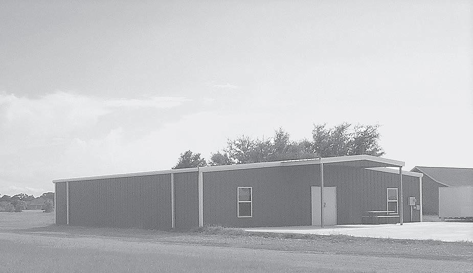
1–18. The light metal storage building is on open flat terrain in central Oklahoma.If the side wall of the building is 14 ft high,what are the two values of the external wind pressure acting on this wall when the wind blows on the back of the building? The roof is essentially flat and the building is fully enclosed.
V = 105 mi h
Kzt = 1.0
Kd = 1.0
qz = 0.00256 K zKztKdV2
= 0.00256 K z (1.0)(1.0)(105)2
= 28.22 K z
From Table 1–5
For 0 … z … 15 ftK z = 0.85
Thus,
qz = 28.22(0.85) = 23.99
p = qGCp - qh(GC pi)
p = (23.99)(0.85)(0.7) - (23.99)(0.18)
p =-9.96 psf or p =-18.6 psf
Ans. ;
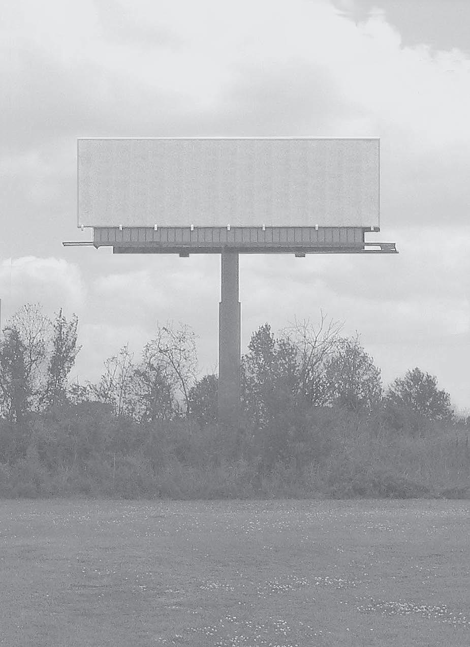
1–19. Determine the resultant force acting perpendicular to the face of the billboard and through its center if it is located in Michigan on open flat terrain.The sign is rigid and has a width of 12 m and a height of 3 m.Its top side is 15m from the ground.
qh = 0.613 K zKztKdV2
Since z = h = 15 m K z = 1.09
Kzt = 1.0
Kd = 1.0
V = 47 m s
qh = 0.613(1.09)(1.0)(1.0)(47)2 = 1476.0 N m2
B s == 4,s h == 0.2
From Table 1–6
Cf = 1.80
F = qh GCf A s = (1476.0)(0.85)(1.80)(12)(3) = 81.3 kN
2012 Pearson Education,Inc.,Upper Saddle River,NJ.All rights reserved.This material is protected under all copyright laws as they currently exist. No portion of this material may be reproduced,in any form or by any means,without permission in writing from the publisher.
*1–20. A hospital located in central Illinois has a flat roof. Determine the snow load in kN m2 that is required to design the roof.
pf = 0.7 C cCtIs p g
pf = 0.7(0.8)(1.0)(1.20)(0.96) = 0.6451 kN m2
Also
pf = I s p g = (1.20)(0.96) = 1.152 kN m2
use
pf = 1.15 kN m2
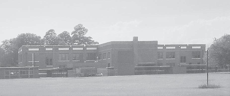
1–21. The school building has a flat roof.It is located in an open area where the ground snow load is 0.68 kN m2. Determine the snow load that is required to design the roof.
pf = 0.7 C cCtIs p g
pf = 0.7(0.8)(1.0)(1.20)(0.68)
= 0.457 kN m2
Also
pf = pf = I s p g = (1.20)(0.68) = 0.816 kN m2
use
pf = 0.816 kN m2
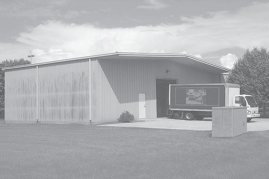
1–22. The hospital is located in an open area and has a flat roof and the ground snow load is 30 lb ft2.Determine the design snow load for the roof.
Since pq = 30 lb ft2 7 20 lb ft2 then pf = I s pg = 1.20(30) = 36 lb ft2
© 2012 Pearson Education,Inc.,Upper Saddle River,NJ.All rights reserved.This material is protected under all copyright laws as they currently exist.No portion of this material may be reproduced,in any form or by any means,without permission in writing from the publisher.
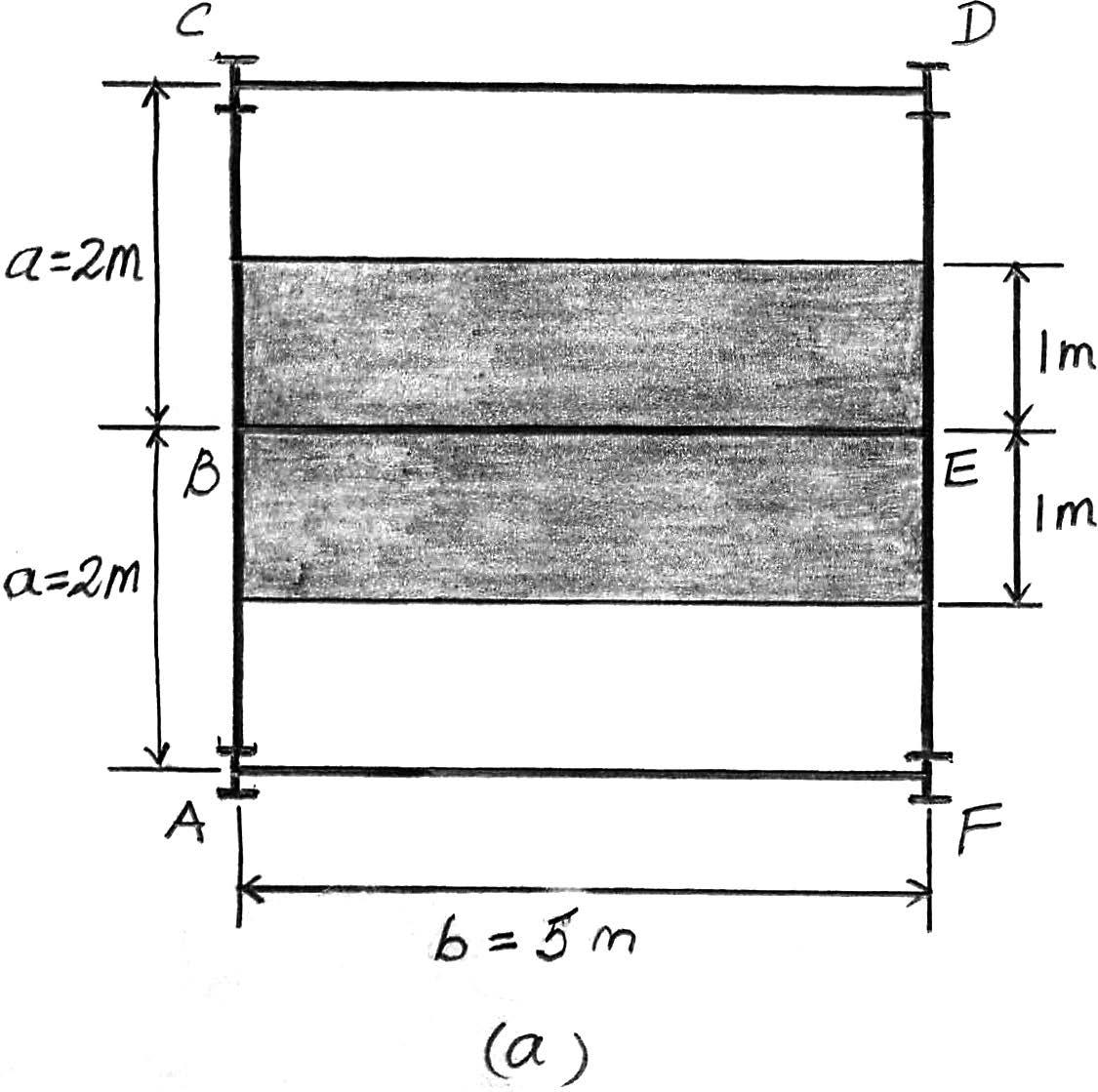
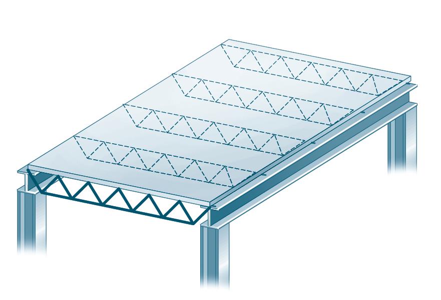
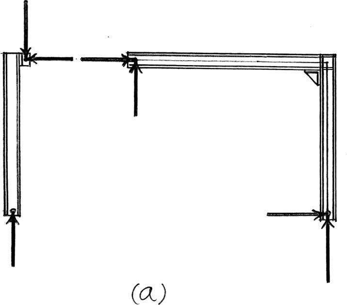
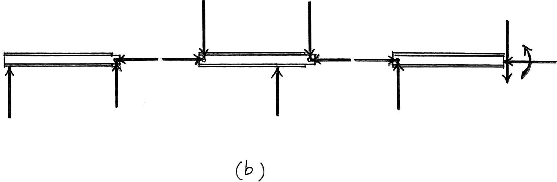
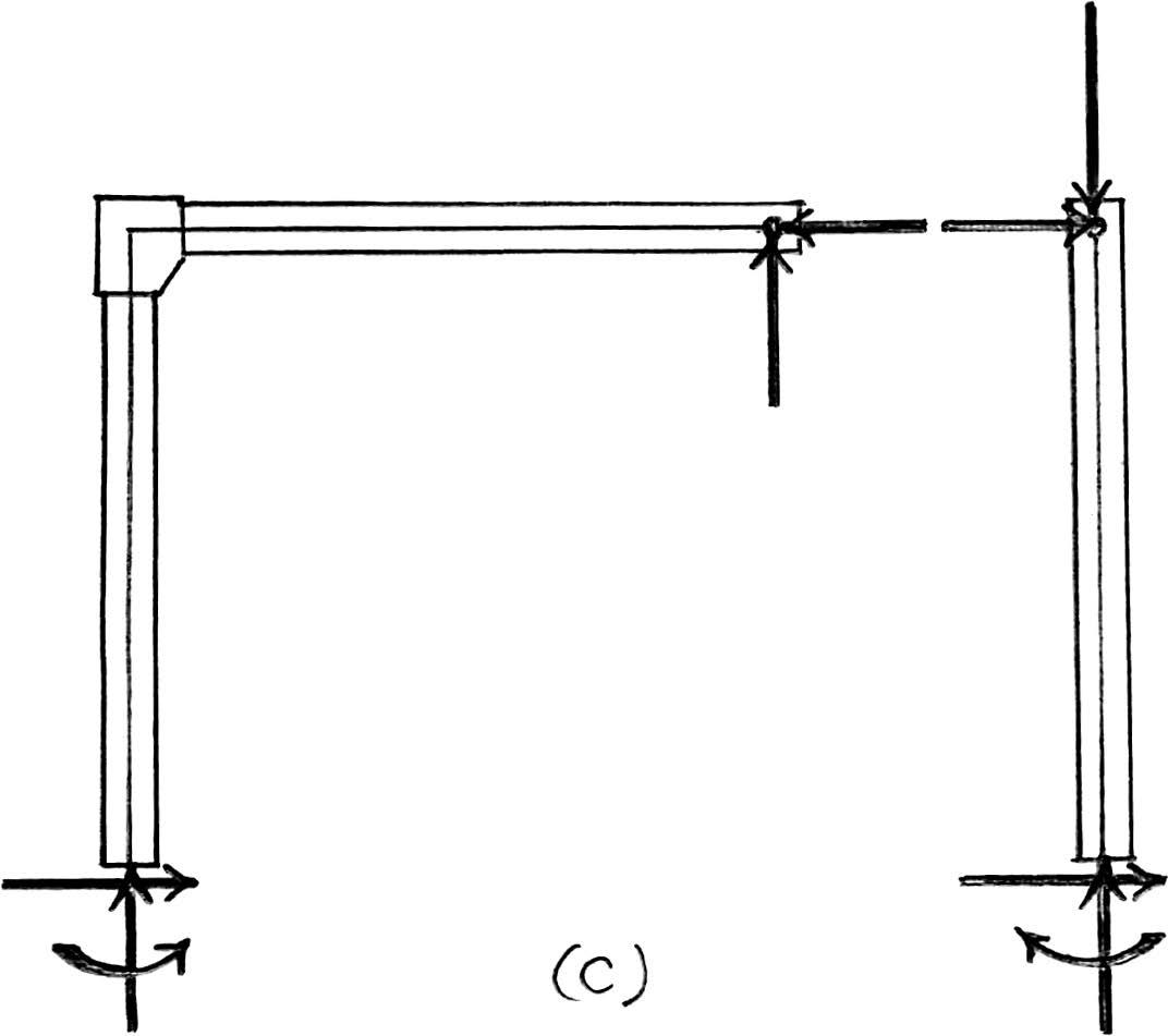
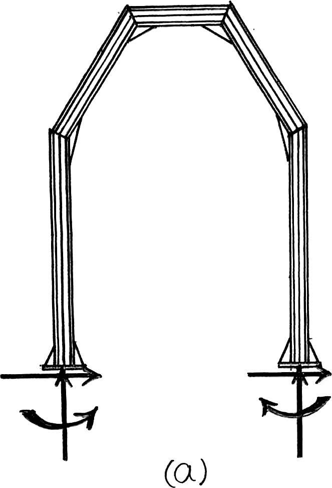
2–1. The steel framework is used to support the reinforced stone concrete slab that is used for an office.The slab is200 mm thick.Sketch the loading that acts along members BE and FED.Take ,. Hint:See Tables1–2 and 1–4.
b = 5 m a = 2 m
b a = 5 m 2 m = 2.5,
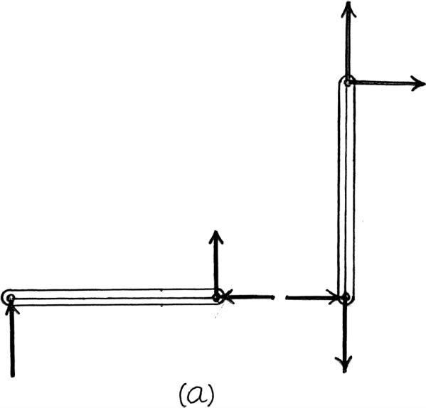
Beam BE.Since the concrete slab will behave as a one way slab.
Thus,the tributary area for this beam is rectangular shown in Fig. a and the intensity of the uniform distributed load is
200 mm thick reinforced stone concrete slab: (23.6 kN>m3)(0.2 m)(2 m) = 9.44 kN>m
Live load for office:(2.40 kN>m2)(2 m) = Ans.
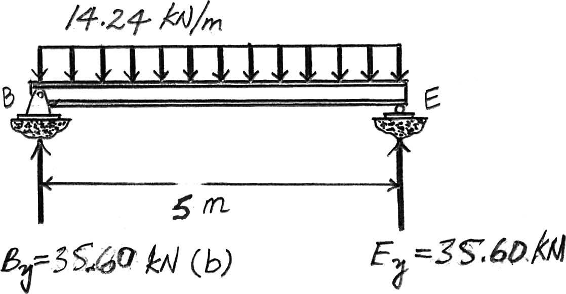
Due to symmetry the vertical reaction at B and E are
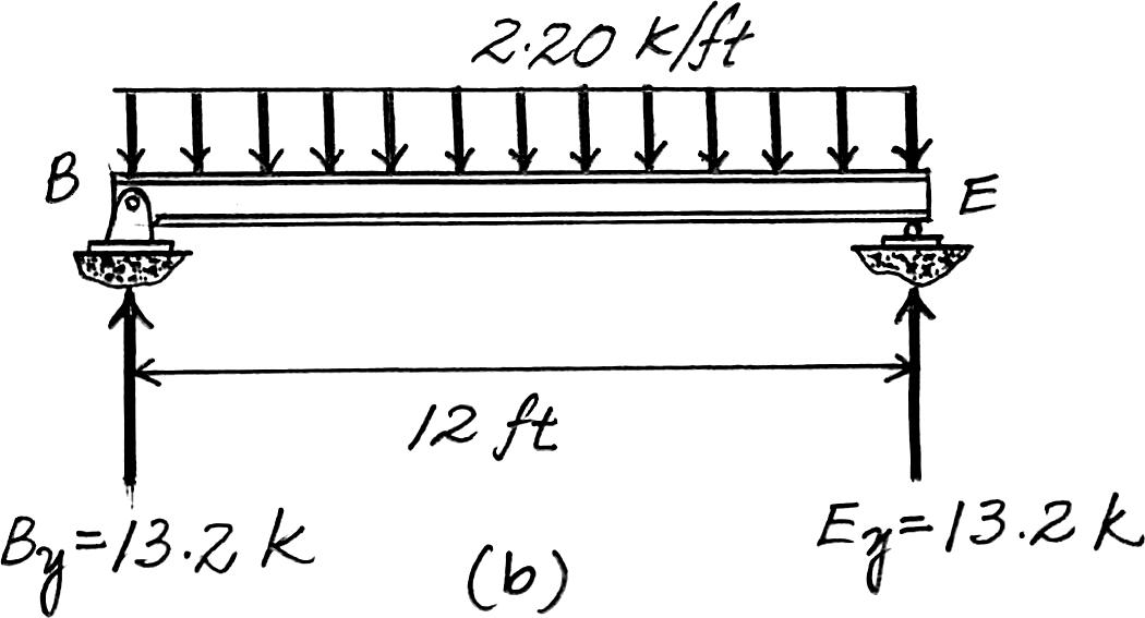
B y = E y = (14.24 kN>m)(5)>2 = 35.6 kN
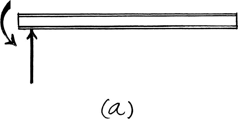
The loading diagram for beam BE is shown in Fig. b.
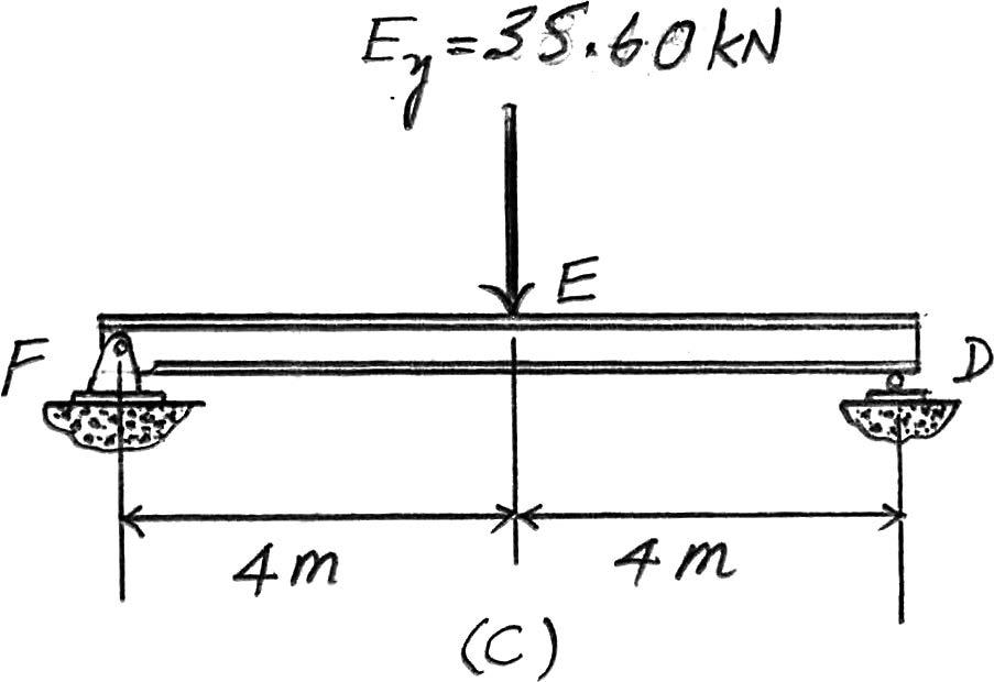
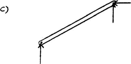
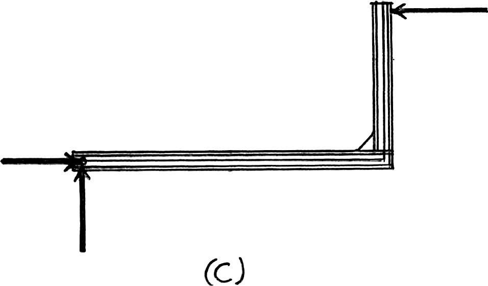
Beam FED. The only load this beam supports is the vertical reaction of beam BE at E which is E y = 35.6 kN.The loading diagram for this beam is shown in Fig. c.
2012 Pearson Education,Inc.,Upper Saddle River,NJ.All rights reserved.This material is protected under all copyright laws as they currently exist.No portion of this material may be reproduced,in any form or by any means,without permission in writing from the publisher.
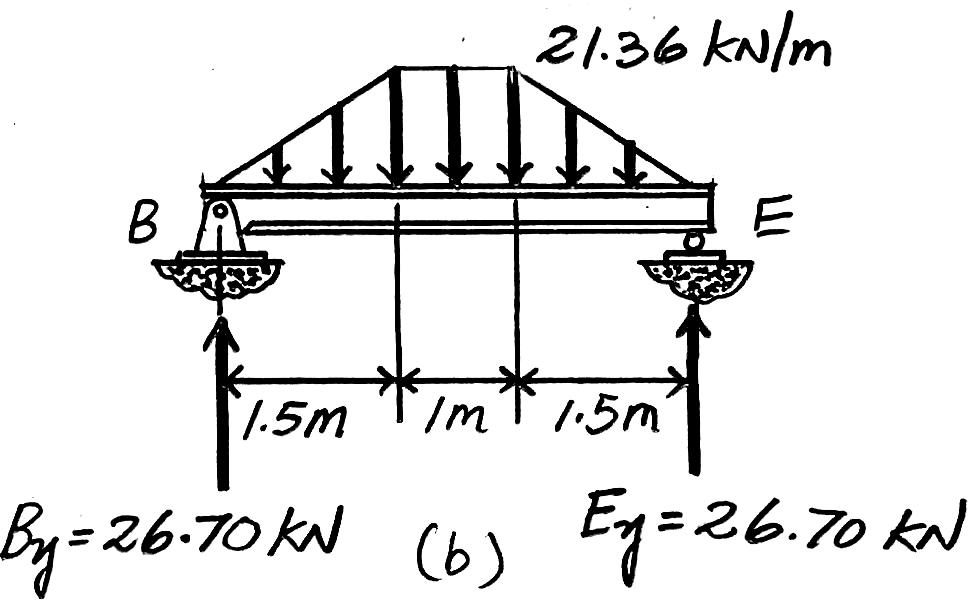
2–2. Solve Prob.2–1 with ,. b = 4 m a = 3 m
Beam BE. Since ,the concrete slab will behave as a two way slab.Thus, the tributary area for this beam is the hexagonal area shown in Fig. a and the maximum intensity of the distributed load is
200 mm thick reinforced stone concrete slab:(23.6 kN>m3)(0.2 m)(3 m) = 14.16 kN>m
Live load for office:(2.40 kN>m2)(3 m) = Ans.
Due to symmetry,the vertical reactions at B and E are = 26.70 kN
The loading diagram for Beam BE is shown in Fig. b
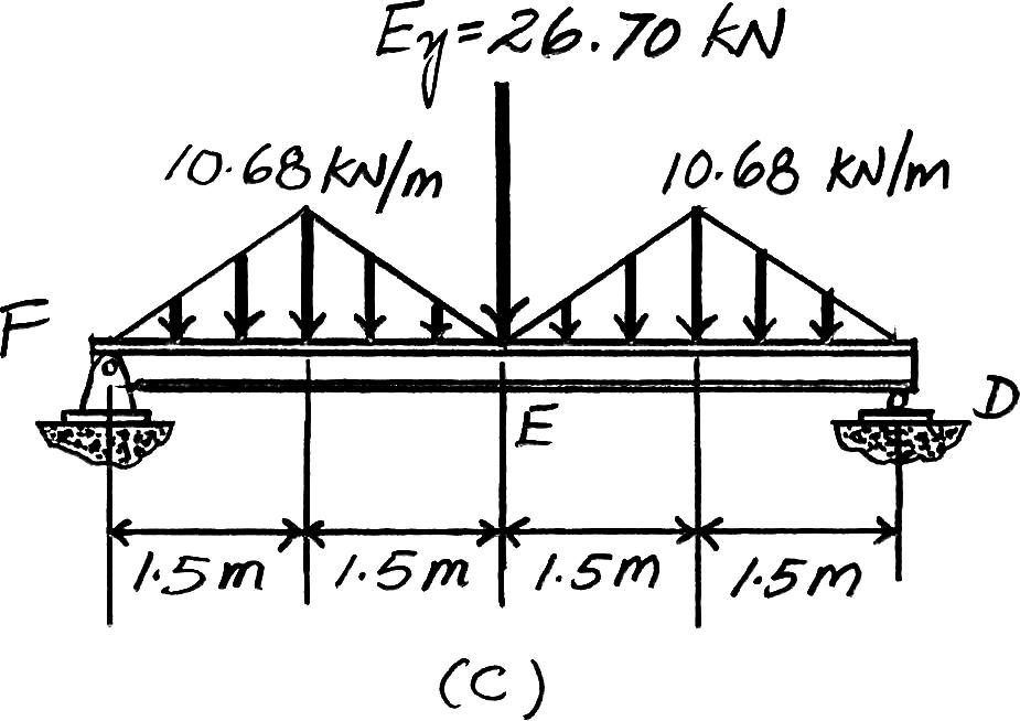
Beam FED. The loadings that are supported by this beam are the vertical reaction of beam BE at E which is E y = 26.70 kN and the triangular distributed load of which its tributary area is the triangular area shown in Fig. a.Its maximum intensity is 200 mm thick reinforced stone concrete slab:(23.6 kN>m3)(0.2 m)(1.5 m) = 7.08 kN>m
Live load for office:(2.40 kN>m2)(1.5 m) = Ans.
The loading diagram for Beam FED is shown in Fig. c

© 2012 Pearson Education,Inc.,Upper Saddle River,NJ.All rights reserved.This material is protected under all copyright laws as they currently exist.No portion of this material may be reproduced,in any form or by any means,without permission in writing from the publisher.
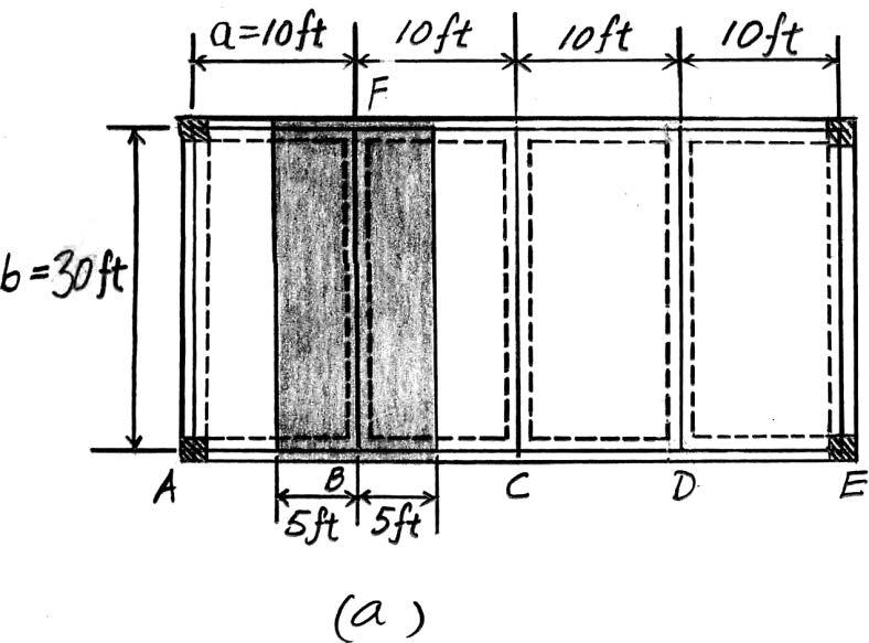
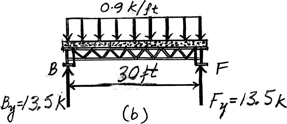
2–3. The floor system used in a school classroom consists of a 4-in.reinforced stone concrete slab.Sketch the loading that acts along the joist BF and side girder ABCDE.Set ,. Hint:See Tables 1–2 and1–4.
b = 30 ft a = 10 ft
Joist BF. Since ,the concrete slab will behave as a one way slab. Thus,the tributary area for this joist is the rectangular area shown in Fig. a and the intensity of the uniform distributed load is
4 in thick reinforced stone concrete slab:(0.15 k>ft3)(10 ft) = 0.5 k>ft
Live load for classroom:(0.04 k>ft2)(10 ft) =
Due to symmetry,the vertical reactions at B and F are B y = F y = (0.9 k>ft)(30 ft)>2 = 13.5 k
The loading diagram for joist BF is shown in Fig. b
Ans.
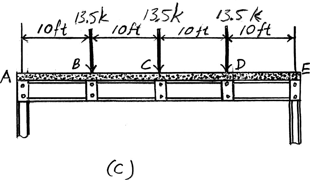
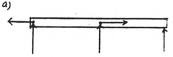
Girder ABCDE. The loads that act on this girder are the vertical reactions of the joists at B, C,and D,which are B y = C y = D y = 13.5 k.The loading diagram for this girder is shown in Fig. c
© 2012 Pearson Education,Inc.,Upper Saddle River,NJ.All rights reserved.This material is protected under all copyright laws as they currently exist.No portion of this material may be reproduced,in any form or by any means,without permission in writing from the publisher.
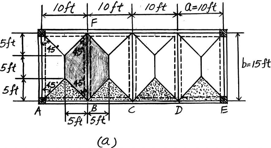
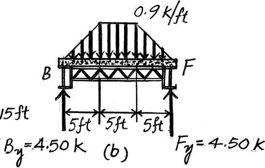
*2–4. Solve Prob.2–3 with ,. b = 15 ft a = 10 ft
b a = 15 ft 10 ft = 1.5 < 2
Joist BF. Since ,the concrete slab will behave as a two way slab.Thus,the tributary area for the joist is the hexagonal area as shown in Fig. a and the maximum intensity of the distributed load is 4 in thick reinforced stone concrete slab:(0.15 k>ft3)(10 ft) = 0.5 k>ft
Live load for classroom:(0.04 k>ft2)(10 ft) = Ans.
Due to symmetry,the vertical reactions at B and G are
Ans.
The loading diagram for beam BF is shown in Fig. b
Girder ABCDE. The loadings that are supported by this girder are the vertical reactions of the joist at B, C and D which are B y = C y = D y = 4.50 k and the triangular distributed load shown in Fig. a.Its maximum intensity is 4 in thick reinforced stone concrete slab:
(0.15 k>ft3)(5 ft) = 0.25 k>ft
Live load for classroom:(0.04 k>ft2)(5 ft) = Ans.
The loading diagram for the girder ABCDE is shown in Fig. c.
© 2012 Pearson Education,Inc.,Upper Saddle River,NJ.All rights reserved.This material is protected under all copyright laws as they currently exist.No portion of this material may be reproduced,in any form or by any means,without permission in writing from the publisher.
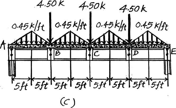
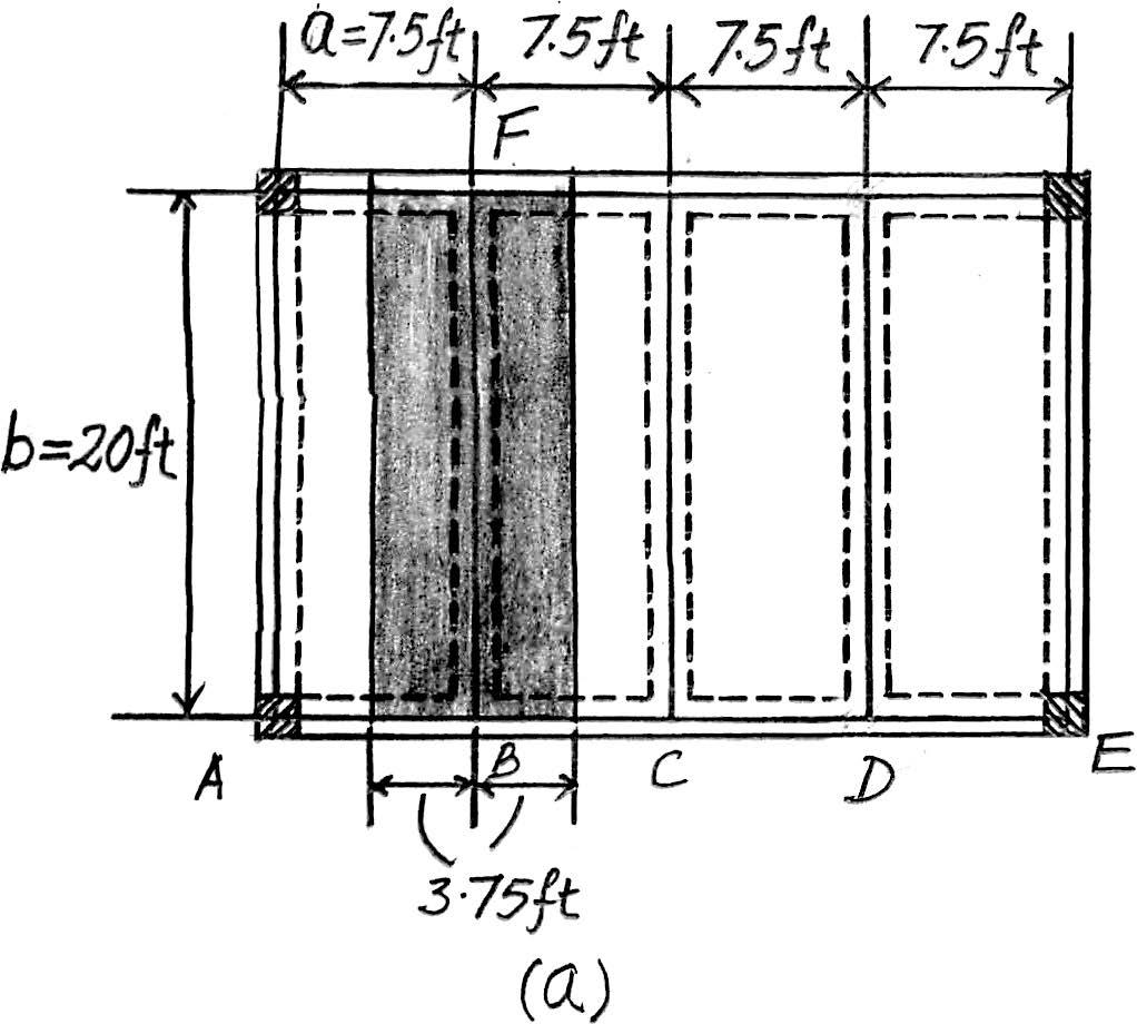
2–5. Solve Prob.2–3 with ,. b = 20 ft a = 7.5 ft
Beam BF. Since ,the concrete slab will behave as a one way slab.Thus,the tributary area for this beam is a rectangle shown in Fig. a and the intensity of the distributed load is
4 in thick reinforced stone concrete slab:(0.15 k>ft3)(7.5 ft) = 0.375 k>ft
Live load from classroom:(0.04 k>ft2)(7.5 ft) = Ans.
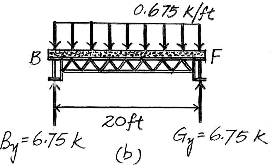
Due to symmetry,the vertical reactions at B and F are
Ans.
The loading diagram for beam BF is shown in Fig. b.
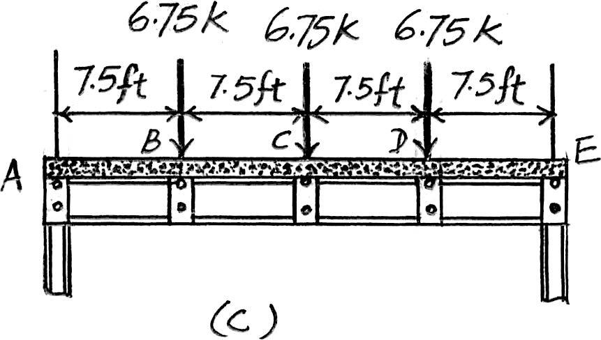
Beam ABCD. The loading diagram for this beam is shown in Fig. c
2012 Pearson Education,Inc.,Upper Saddle River,NJ.All rights reserved.This material is protected under all copyright laws as they currently exist.No portion of this material may be reproduced,in any form or by any means,without permission in writing from the publisher.
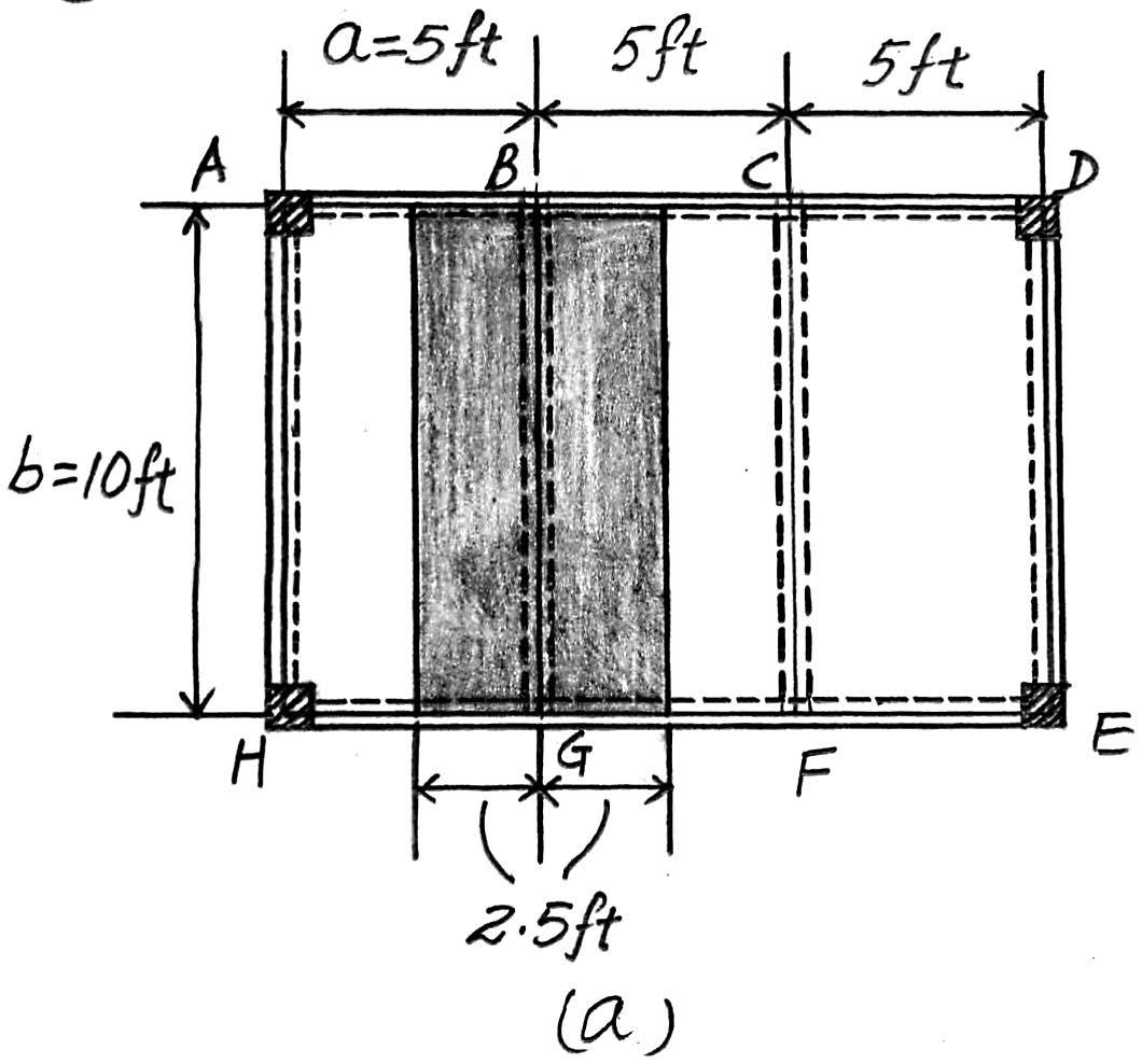
2–6. The frame is used to support a 2-in.-thick plywood floor of a residential dwelling.Sketch the loading that acts along members BG and ABCD.Set ,. Hint: See Tables 1–2 and 1–4. b = 15 ft a = 5 ft
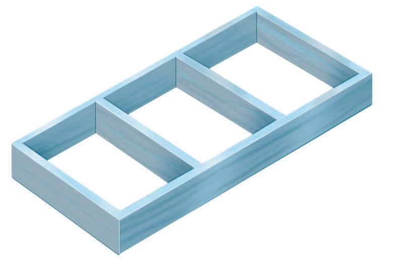
Beam BG. Since == 3,the plywood platform will behave as a one way slab.Thus,the tributary area for this beam is rectangular as shown in Fig. a and the intensity of the uniform distributed load is 2 in thick plywood platform: (5ft) = 30 lb>ft a 2 12 ft b a 36 lb ft2 b 15 ft 5 ft b a
Line load for residential dweller:(5 ft) = Ans.
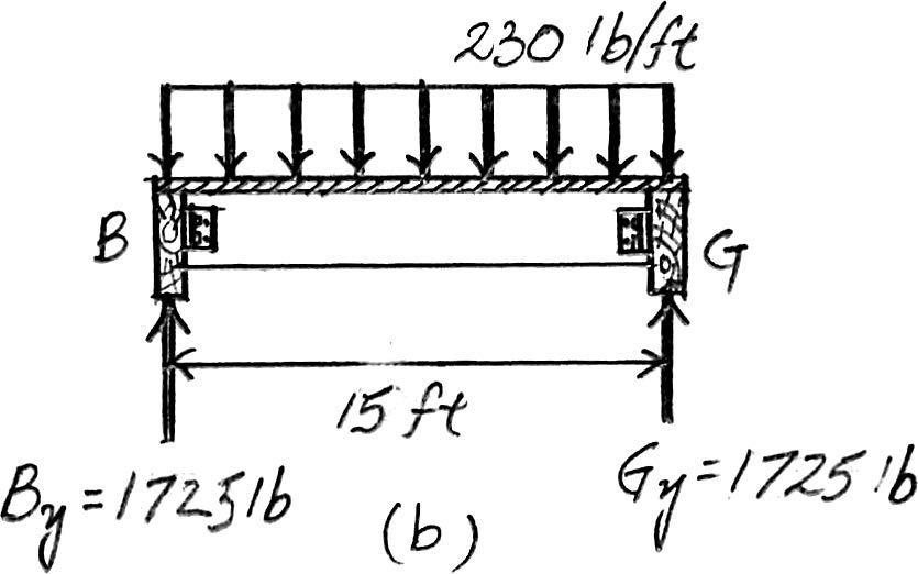
Due to symmetry,the vertical reactions at B and G are
B y = G y == 1725
The loading diagram for beam BG is shown in Fig. a
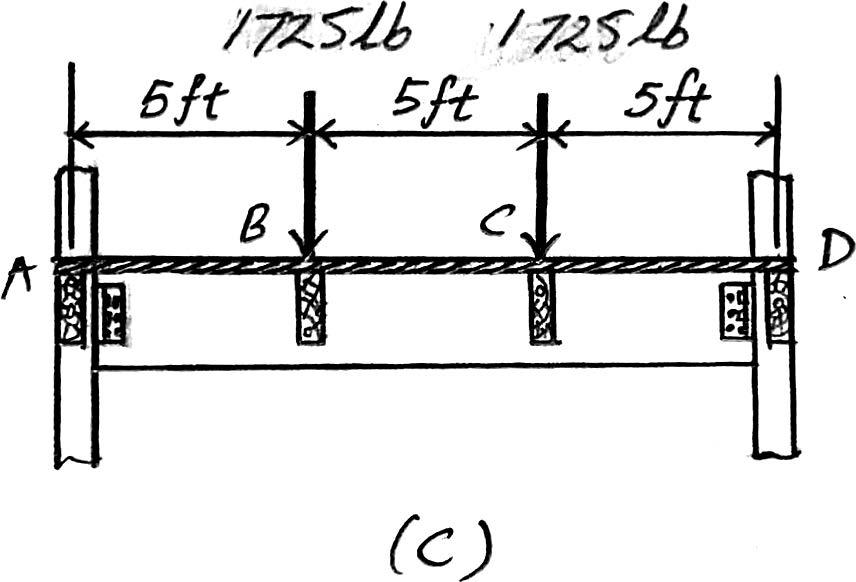
Beam ABCD. The loads that act on this beam are the vertical reactions of beams BG and CF at B and C which are B y = C y = 1725 lb.The loading diagram is shown in Fig. c (230 lb> ft)(15 ft) 2
material is protected under all copyright laws as they currently exist.No portion of this material may be reproduced,in any form or by any means,without permission in writing from the publisher.
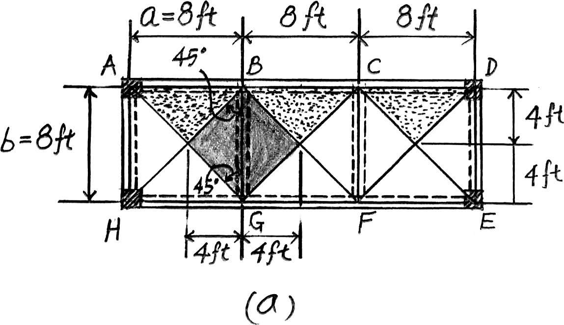
Prob.2–6,with ,. b = 8 ft a = 8 ft
Beam BG. Since ,the plywood platform will behave as a two way slab.Thus,the tributary area for this beam is the shaded square area shown in Fig. a and the maximum intensity of the distributed load is b a = 8 ft 8 ft = 1 < 2
2 in thick plywood platform:(36 lb>ft3)
Live load for residential dwelling: Ans.
Due to symmetry,the vertical reactions at B and G are = 736 lb
= Gy =
The loading diagram for the beam BG is shown in Fig. b
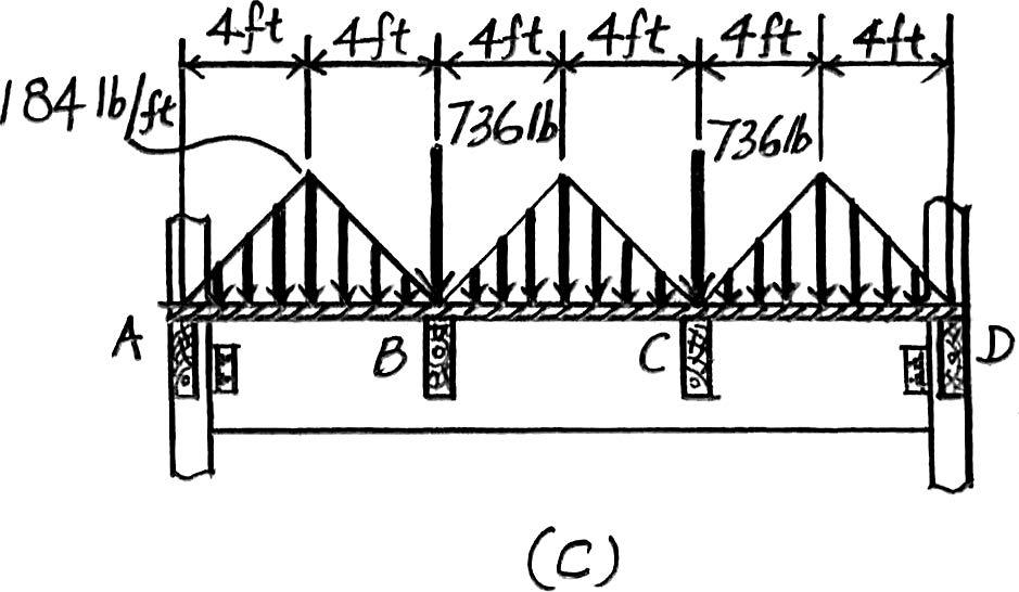
Beam ABCD. The loadings that are supported by this beam are the vertical reactions of beams BG and CF at B and C which are B y = C y = 736 lb and the distributed load which is the triangular area shown in Fig. a.Its maximum intensity is
2 in thick plywood platform:
The loading diagram for beam ABCD is shown in Fig. c (40
Live load for residential dwelling: Ans.

© 2012 Pearson Education,Inc.,Upper Saddle River,NJ.All rights reserved.This material is protected under all copyright laws as they currently exist.No portion of this material may be reproduced,in any form or by any means,without permission in writing from the publisher.
*2–8. Solve Prob.2–6,with ,. b = 15 ft a = 9 ft
Beam BG. Since ,the plywood platform will behave as a two way slab.Thus,the tributary area for this beam is the octagonal area shown in Fig. a and the maximum intensity of the distributed load is b a = 15 ft 9 ft = 1.67 < 2
2 in thick plywood platform:
Live load for residential dwelling: Ans.
Due to symmetry,the vertical reactions at B and G are
By = Gy =
The loading diagram for beam BG is shown in Fig. b
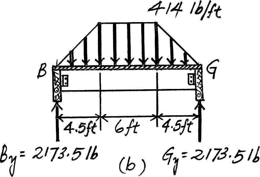
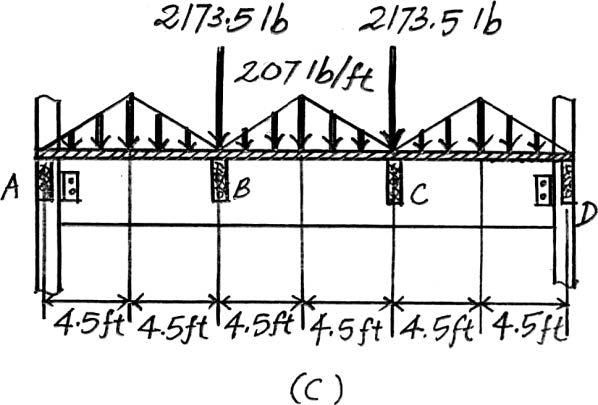
Beam ABCD. The loading that is supported by this beam are the vertical reactions of beams BG and CF at B and C which is B y = C y = 2173.5 lb and the triangular distributed load shown in Fig. a.Its maximum intensity is
2 in thick plywood platform:
Live load for residential dwelling: Ans.
The loading diagram for beam ABCD is shown in Fig. c.

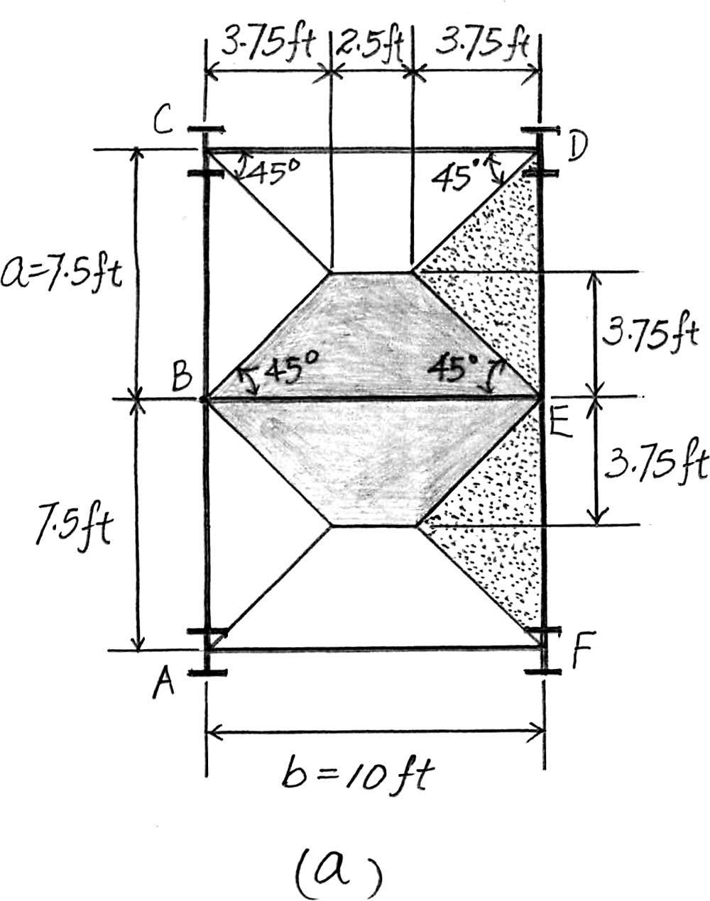
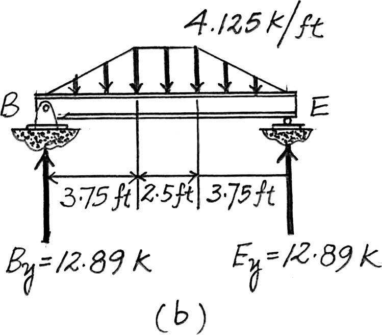
2–9. The steel framework is used to support the 4-in. reinforced stone concrete slab that carries a uniform live loading of .Sketch the loading that acts along members BE and FED.Set ,. Hint:See Table 1–2. a = 7.5 ft b = 10 ft
500 lb> ft2
Beam BE. Since = < 2,the concrete slab will behave as a two way slab. Thus,the tributary area for this beam is the octagonal area shown in Fig. a and the maximum intensity of the distributed load is
4 in thick reinforced stone concrete slab:
Floor Live Load: Ans.
Due to symmetry,the vertical reactions at B and E are
The loading diagram for this beam is shown in Fig. b
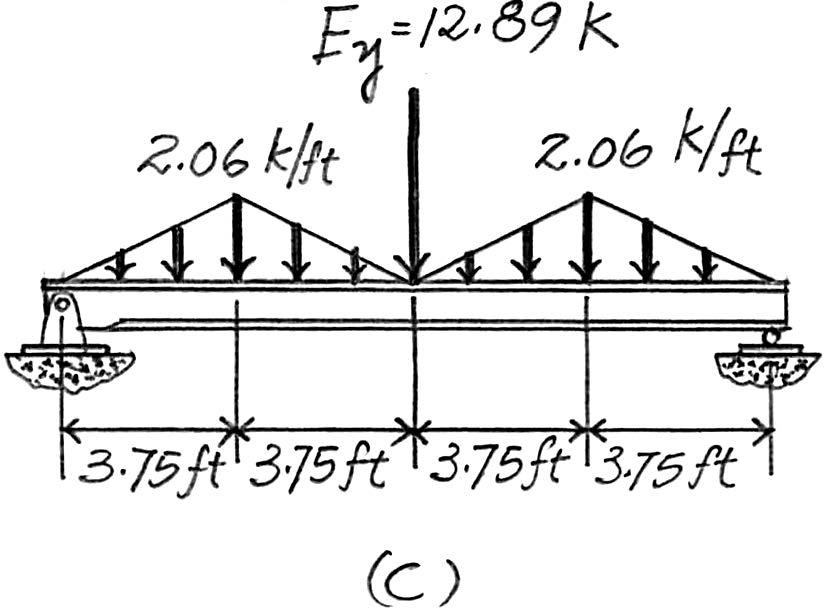
Beam FED. The loadings that are supported by this beam are the vertical reaction of beam BE at E which is E y = 12.89 k and the triangular distributed load shown in Fig. a.Its maximum intensity is
4 in thick reinforced stone concrete slab:
Floor live load: Ans.
The loading diagram for this beam is shown in Fig. c
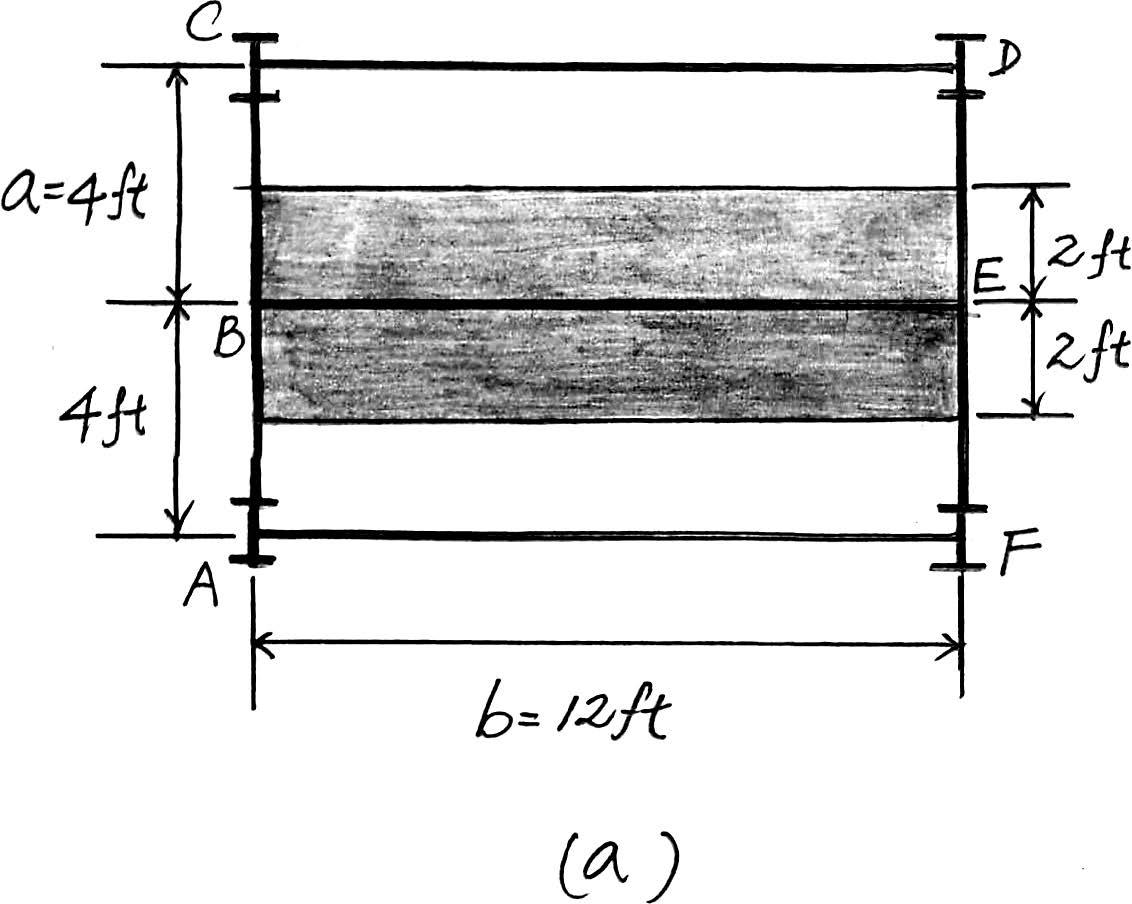
2–10. Solve Prob.2–9,with ,. a = 4 ft b = 12 ft
Beam BE. Since ,the concrete slab will behave as a one way slab.Thus,the tributary area for this beam is the rectangular area shown in Fig. a and the intensity of the distributed load is b a = 12 4 = 3 > 2
4 in thick reinforced stone concrete slab:
Floor Live load: Ans.
Due to symmetry,the vertical reactions at B and E are
By = Ey =
The loading diagram of this beam is shown in Fig. b.
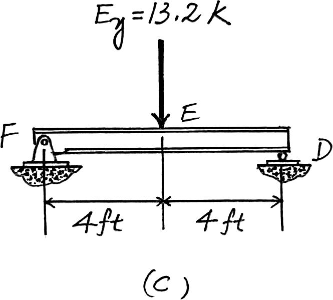
Beam FED. The only load this beam supports is the vertical reaction of beam BE at E which is E y = 13.2 k. Ans.
The loading diagram is shown in Fig. c
2012 Pearson Education,Inc.,Upper
River,NJ.All
reserved.This material is protected under all copyright laws as they currently exist.No portion of this material may be reproduced,in any form or by any means,without permission in writing from the publisher.
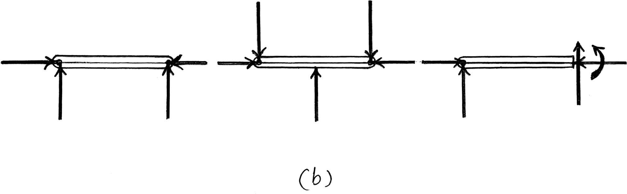
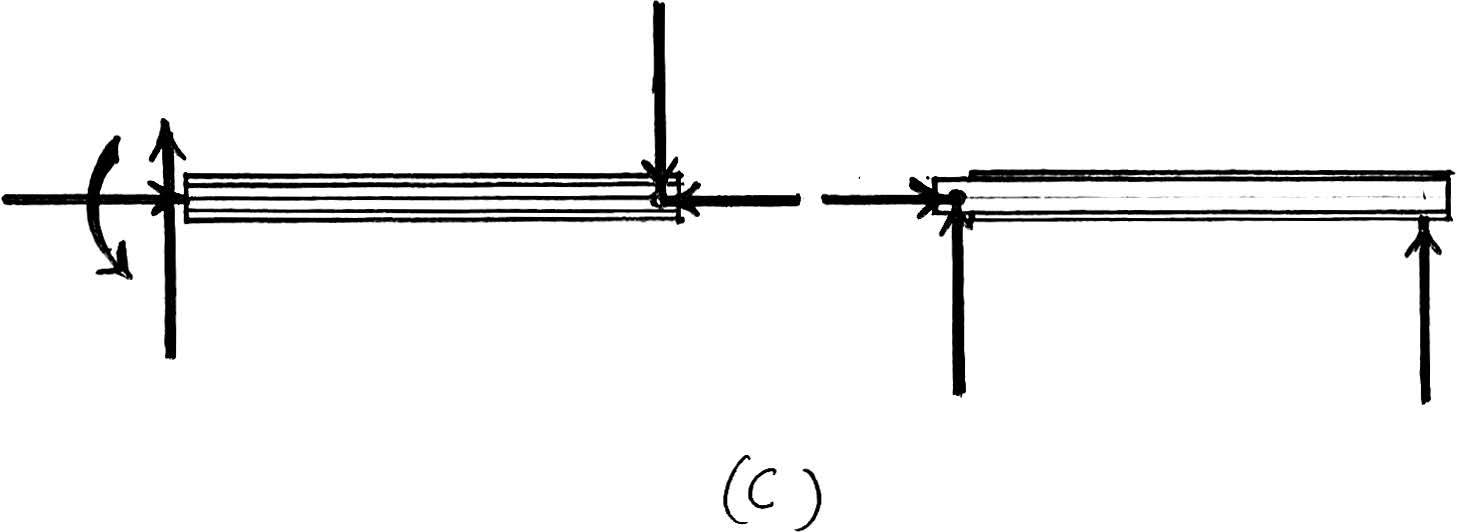
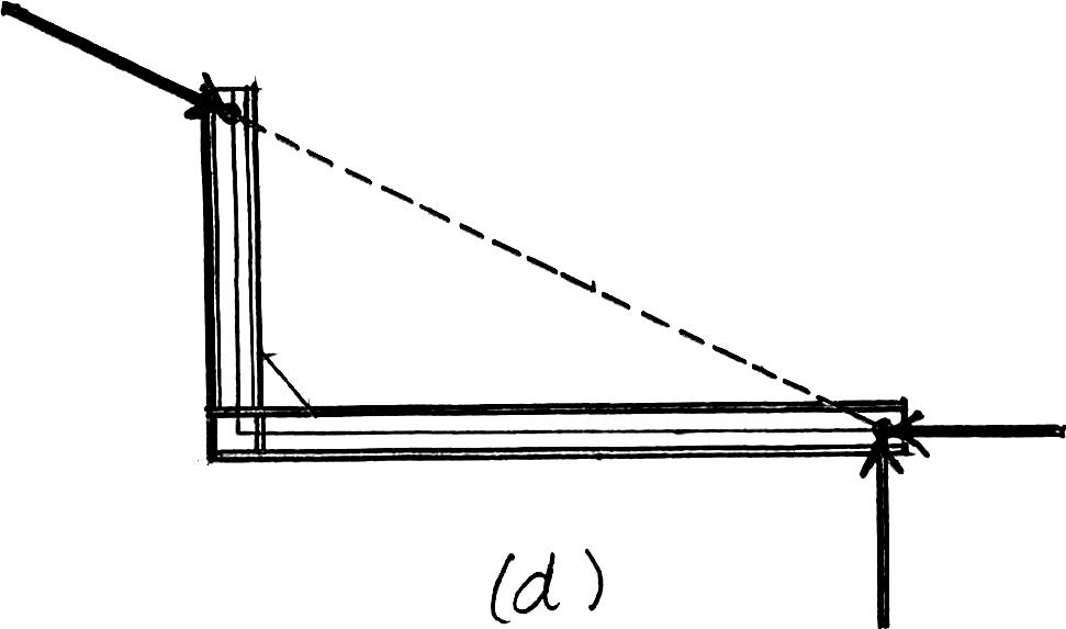
2–11. Classify each of the structures as statically determinate,statically indeterminate,or unstable.If indeterminate,specify the degree of indeterminacy.The supports or connections are to be assumed as stated.


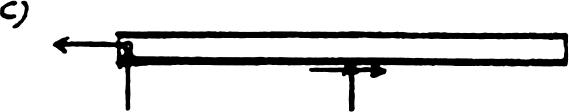
(a) r = 53n = 3(1) 6 5
Indeterminate to 2°. Ans.
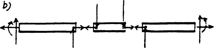
(b)Parallel reactions
Unstable. Ans.
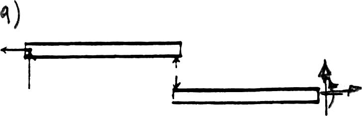
(c) r = 33n = 3(1) 6 3
Statically determinate. Ans.
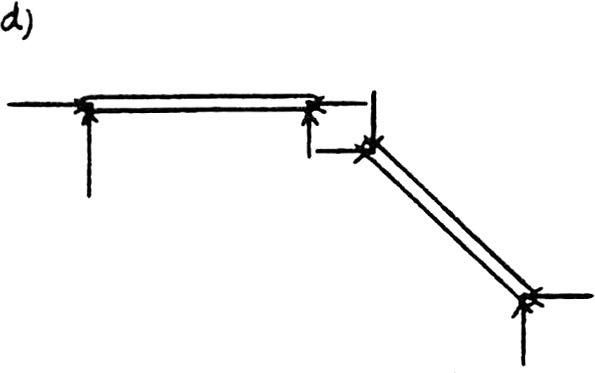
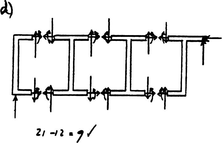
(d) r = 63n = 3(2) 6 6
Statically determinate. Ans.
(e)Concurrent reactions
Unstable. Ans.
Pearson Education,Inc.,Upper Saddle River,NJ.All rights reserved.This material is protected under all copyright laws as they currently exist.No portion of this material may be reproduced,in any form or by any means,without permission in writing from the publisher.
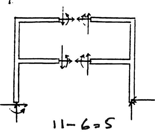
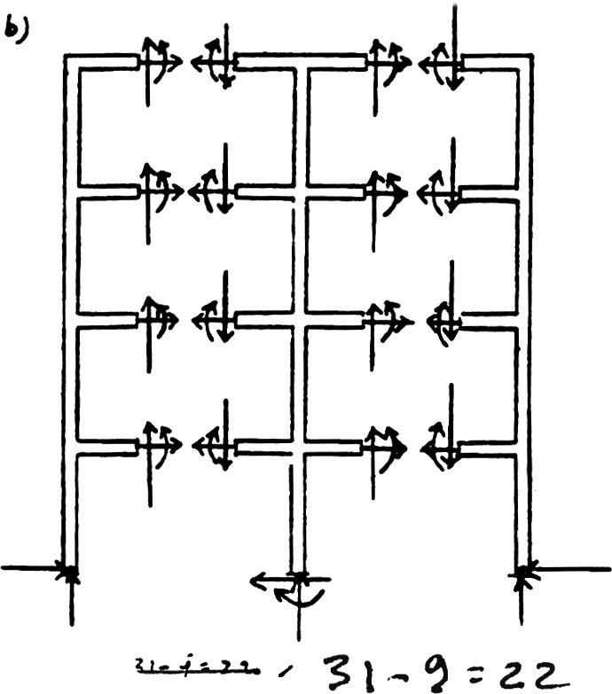
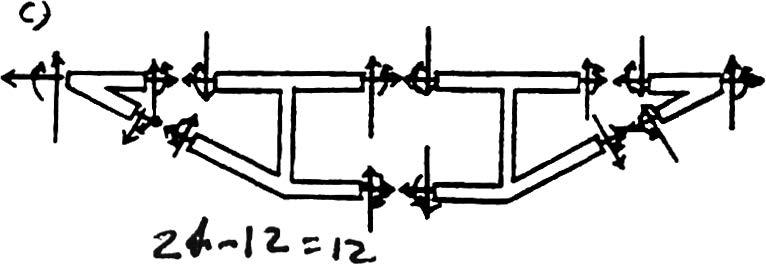
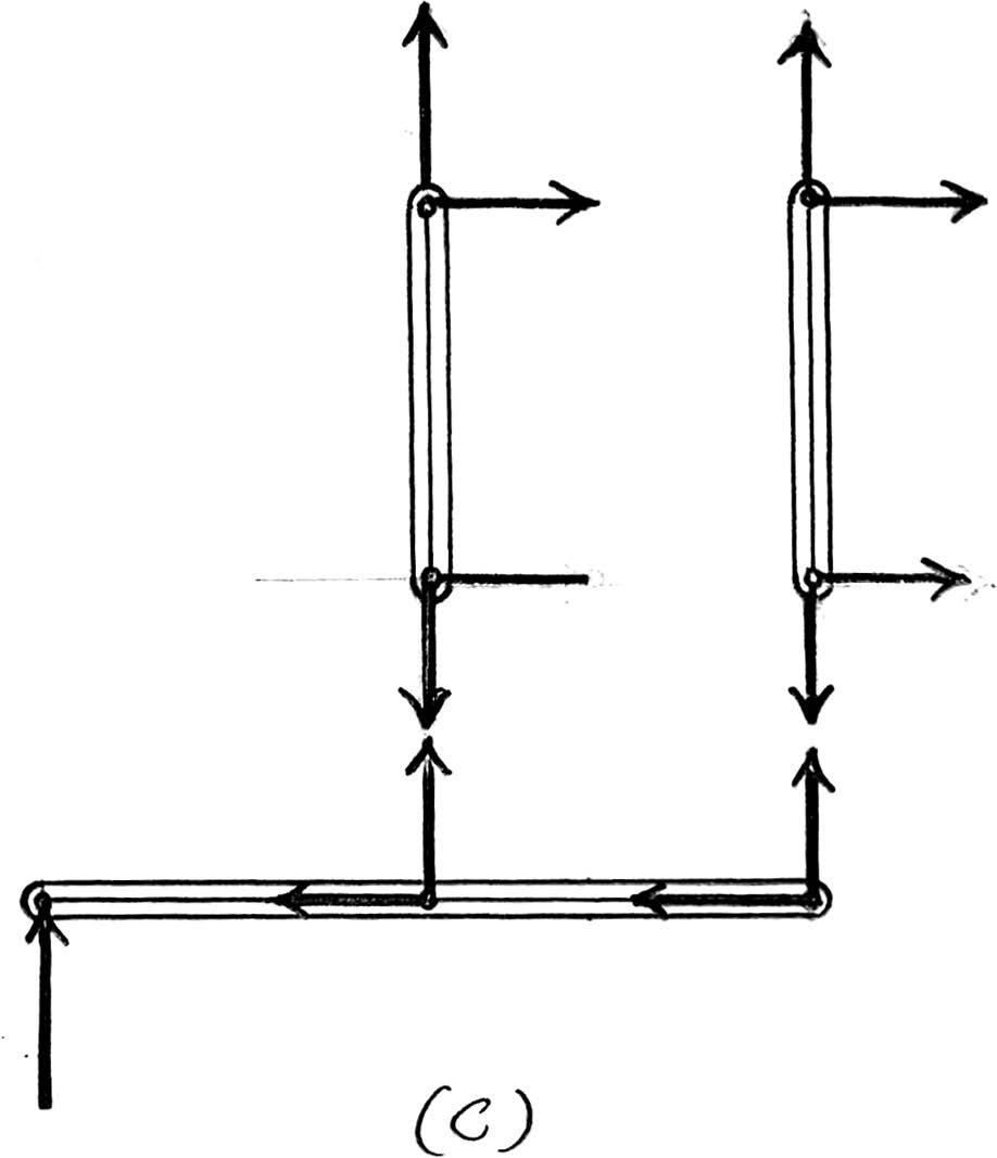
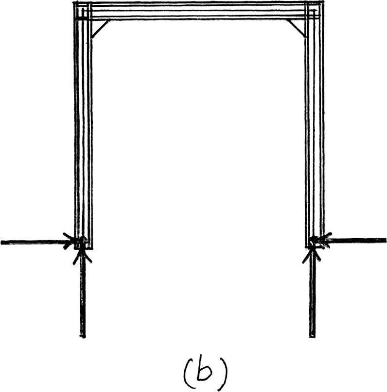
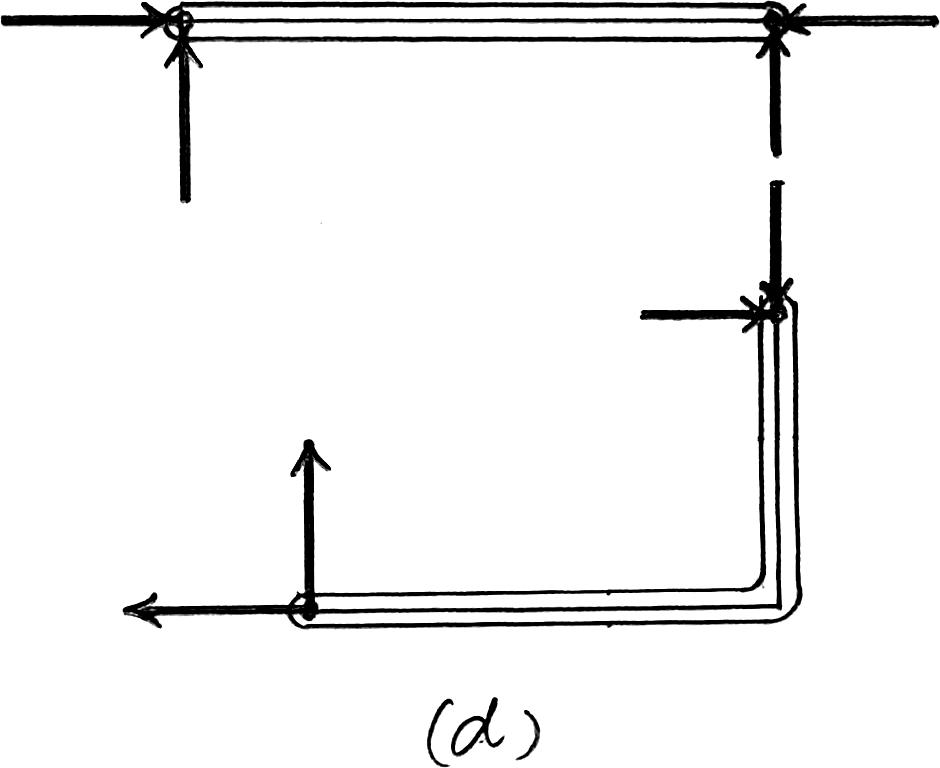
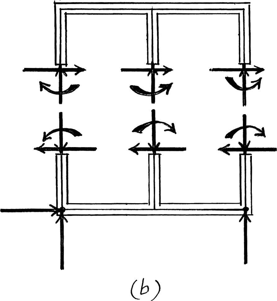
*2–12. Classify each of the frames as statically determinate or indeterminate.If indeterminate,specify the degree of indeterminacy.All internal joints are fixed connected.
(a)Statically indeterminate to 5°.
(b)Statically indeterminate to 22°.
(c)Statically indeterminate to 12°.
(d)Statically indeterminate to 9°.
Ans.
Ans.
Ans.
Ans.
© 2012 Pearson Education,Inc.,Upper Saddle River,NJ.All rights reserved.This material is protected under all copyright laws as they currently exist.No portion of this material may be reproduced,in any form or by any means,without permission in writing from the publisher.
2–13. Classify each of the structures as statically determinate,statically indeterminate,stable,or unstable. If indeterminate,specify the degree of indeterminacy. The supports or connections are to be assumed as stated.
(a) r = 63n = 3(2) = 6
Statically determinate.
(b) r = 103n = 3(3) 6 10
Statically indeterminate to 1°.
(c) r = 43n = 3(1) 6 4
Statically determinate to 1°.
Ans.
Ans.
Ans.
© 2012 Pearson Education,Inc.,Upper Saddle River,NJ.All rights reserved.This material is protected under all copyright laws as they currently exist.No portion of this material may be reproduced,in any form or by any means,without permission in writing from the publisher.
2–14. Classify each of the structures as statically determinate,statically indeterminate,stable,or unstable.If indeterminate,specify the degree of indeterminacy.The supports or connections are to be assumed as stated.
(a)
r = 53n = 3(2) = 6
r 6 3n
Unstable.
(b)
r = 93n = 3(3) = 9
r = 3n
Stable and statically determinate.
(c)
r = 83n = 3(2) = 6
r - 3n = 8 - 6 = 2
Stable and statically indeterminate to the second degree.
2012 Pearson Education,Inc.,Upper Saddle River,NJ.All
reserved.This material is protected under all copyright laws as they currently exist.No portion of this material may be reproduced,in any form or by any means,without permission in writing from the publisher.
2–15. Classify each of the structures as statically determinate,statically indeterminate,or unstable.If indeterminate,specify the degree of indeterminacy.
(a)
r = 53n = 3(2) = 6
r 6 3n Unstable.
(b)
r = 103n = 3(3) = 9 and r - 3n = 10 - 9 = 1
Stable and statically indeterminate to first degree.
(c)Since the rocker on the horizontal member can not resist a horizontal force component,the structure is unstable.
2012 Pearson Education,Inc.,Upper Saddle River,NJ.All rights reserved.This material is protected under all copyright laws as they currently exist.No portion of this material may be reproduced,in any form or by any means,without permission in writing from the publisher.
*2–16. Classify each of the structures as statically determinate,statically indeterminate,or unstable.If indeterminate,specify the degree of indeterminacy.
(a)
r = 63n = 3(1) = 3
r - 3n = 6 - 3 = 3
Stable and statically indeterminate to the third degree.
(b)
r = 43n = 3(1) = 3
r - 3n = 4 - 3 = 1
Stable and statically indeterminate to the first degree.
(c)
r = 33n = 3(1) = 3 r = 3n
Stable and statically determinate.
(d)
r = 63n = 3(2) = 6 r = 3n
Stable and statically determinate.
© 2012 Pearson Education,Inc.,Upper Saddle River,NJ.All rights reserved.This material is protected under all copyright laws as they currently exist.No portion of this material may be reproduced,in any form or by any means,without permission in writing from the publisher.
2–17. Classify each of the structures as statically determinate,statically indeterminate,stable,or unstable.If indeterminate,specify the degree of indeterminacy.
(a)
r = 23n = 3(1) = 3 r 6 3n
Unstable.
(b)
r = 123n = 3(2) = 6 r 7 3n
r - 3n = 12 - 6 = 6
Stable and statically indeterminate to the sixth degree.
(c)
r = 63n = 3(2) = 6
r = 3n
Stable and statically determinate.
(d)Unstable since the lines of action of the reactive force components are concurrent.
© 2012 Pearson Education,Inc.,Upper Saddle River,NJ.All rights reserved.This material is protected under all copyright laws as they currently exist.No portion of this material may be reproduced,in any form or by any means,without permission in writing from the publisher.
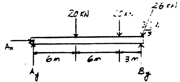
2–18. Determine the reactions on the beam.Neglect the thickness of the beam.
+ a MA = 0; By1152 - 20162 - 201122 - 26 a 12 13 b1152 = 0
By = 48.0 kN
+ c a Fy = 0; Ay + 48.0 - 20 - 2012 13 1262 = 0
Ay = 16.0 kN
: + a Fx = 0; Ax - a 5 13 b 26 = 0
Ax = 10.0 kN
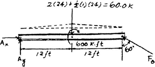
2–19. Determine the reactions on the beam.
+ a MA = 0; - 601122 - 600 + FB cos 60° (242 = 0
FB = 110.00 k = 110 k Ans.
: + a Fx = 0;
+c a Fy = 0;
A x = 110.00 sin 60º = 0
Ax = 95.3 k
A y = 110.00 cos 60º - 60 = 0
Ay = 5.00 k
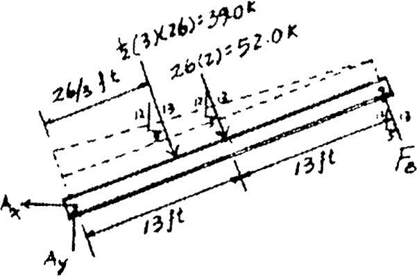
*2–20. Determine the reactions on the beam.
Ans.
Ans.
+ a MA = 0; FB(26) – 52(13) – 39 a 1 3 b (26) = 0
FB = 39.0 k
+ c a Fy = 0; Ay –12 13 (39) – a 12 13 b 52 + a 12 13 b (39.0) = 0
Ay = 48.0 k
: + a Fx = 0; - Ax + a 5 13 b 39 + a 5 13 b
Ax = 20.0 k
= 0
© 2012 Pearson Education,Inc.,Upper Saddle River,NJ.All rights reserved.This material is protected under all copyright laws as they currently exist.No portion of this material may be reproduced,in any form or by any means,without permission in writing from the publisher.
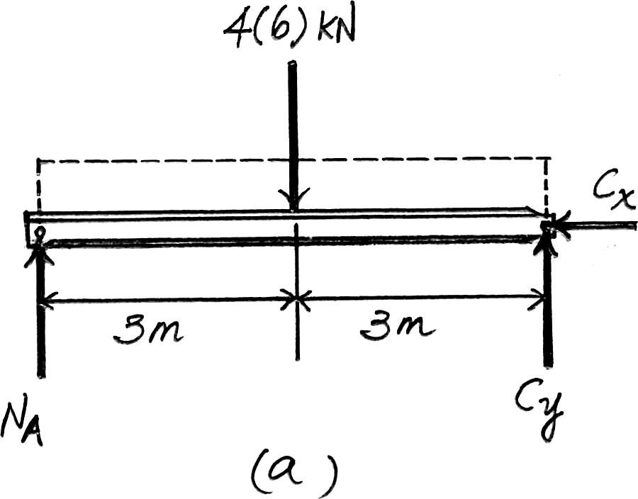
2–21. Determine the reactions at the supports A and B of the compound beam.Assume there is a pin at C 4 kN/ m
Equations of Equilibrium:First consider the FBD of segment AC in Fig. a NA and C y can be determined directly by writing the moment equations of equilibrium about C and A respectively.
+ a MC = 0; 4(6)(3) - NA(6) = 0 NA = 12 kN
Ans. a
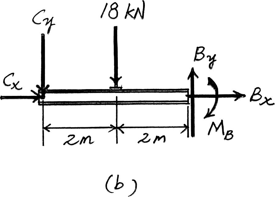
Then, Using the FBD of segment CB,Fig. b,
+ c a Fy = 0; By - 12 - 18 = 0 By = 30 kN : + a Fx = 0 ; 0 + Bx = 0 Bx = 0 : + a Fx = 0 ; 0 - Cx = 0 Cx = 0 + a MA = 0; Cy(6) - 4(6)(3) = 0 Cy = 12 kN
Ans.
Ans.
Ans. a
Ans. + a MB = 0; 12(4) + 18(2) - MB = 0 MB = 84 kN # m