Technical drawing with engineering graphics 16th edition frederick e. giesecke download pdf
Visit to download the full and correct content document: https://ebookmass.com/product/technical-drawing-with-engineering-graphics-16th-edit ion-frederick-e-giesecke/
More products digital (pdf, epub, mobi) instant download maybe you interests ...
ePUB is an open, industry-standard format for eBooks. However, support of ePUB and its many features varies across reading devices and applications. Use your device or app settings to customize the presentation to your liking. Settings that you can customize often include font, font size, single or double column, landscape or portrait mode, and figures that you can click or tap to enlarge. For additional information about the settings and features on your reading device or app, visit the device manufacturer’s Web site. Many titles include programming code or configuration examples. To optimize the presentation of these elements, view the eBook in single-column, landscape mode and adjust the font size to the smallest setting. In addition to presenting code and configurations in the reflowable text format, we have included images of the code that mimic the presentation found in the print book; therefore, where the reflowable format may compromise the presentation of the code listing, you will see a “Click here to view code image” link. Click the link to view the print-fidelity code image. To return to the previous page viewed, click the Back button on your device or app.
Sheet Layouts
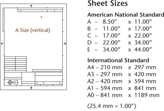
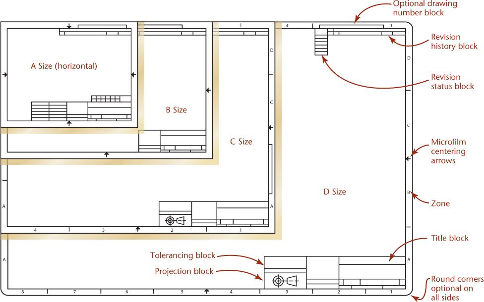
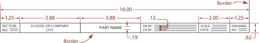
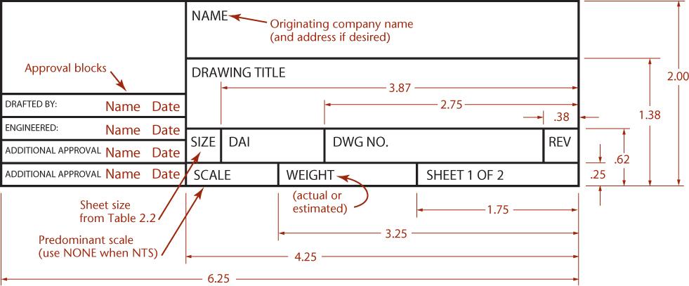
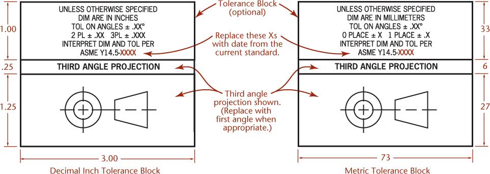
Useful sheet size and title block information is shown here. All of the dimensions are in inches except for Fig. VII, where the example on the right is in millimeters and shows a typical tolerance block for a metric drawing.
Most CAD systems provide standard title blocks that you can insert automatically. Use layouts similar to these or blocks available in your CAD system as assigned by your instructor. If assigned, use the proportions shown here and design your own custom title block that provides the necessary information.
Fig. I Vertical A Size Sheet Layout
Fig. II Example Layouts for A through D Size Sheets
III Narrow Title Strip for a B Size Sheet
Fig.
Fig. IV Typical Title Block
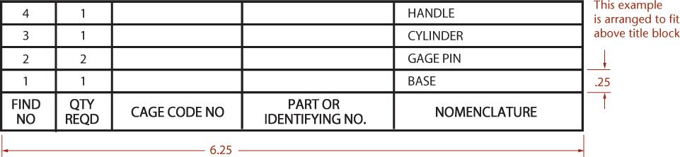
Fig. V Typical Parts List or Materials List
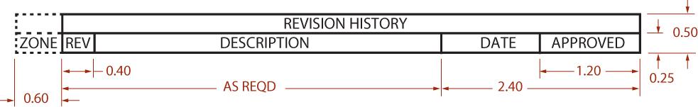
Fig. VI Typical Revision History Block
Fig. VII Inch and Millimeter Tolerance Block Examples. Note thatboth show thirdangleprojection. Use the symbolfor firstangleprojection when appropriate.
Credits and acknowledgments borrowed from other sources and reproduced, with permission, in this textbook appear on the appropriate page within the text. Credits for artwork from EngineeringDesignCommunication,SecondEdition, by Lockhart and Johnson, appear on page C-1. Unless otherwise stated, all artwork has been provided by the authors.
SolidWorks® is a registered trademark of Dassault Systèmes SolidWorks Corporation.
Autodesk, AutoCAD, Autodesk Inventor, Civil 3D, DWG, and the DWG logo are registered trademarks of Autodesk, Inc., in the U.S.A. and certain other countries.
PTC, Creo, and Windchill are trademarks or registered trademarks of PTC Inc. or its subsidiaries in the United States and in other countries.
form or by any means, electronic, mechanical, photocopying, recording, or likewise. For information regarding permissions, request forms, and the appropriate contacts within the Pearson Education Global Rights & Permissions Department, please visit www.pearson.com/permissions.
Many of the designations by manufacturers and seller to distinguish their products are claimed as trademarks. Where those designations appear in this book, and the publisher was aware of a trademark claim, the designations have been printed in initial caps or all caps.
Library of Congress Control Number: 2022950831
ScoutAutomatedPrintCode
pearson.com
ISBN 10: 0-13-806572-1
ISBN 13: 978-0-13-806572-0
About this Book
The sixteenth edition of Giesecke’s Technical Drawing with Engineering Graphics is a comprehensive introduction and detailed reference for creating 3D models and 2D documentation drawings.
Continuing its reputation as a trusted reference, this edition is updated to convey recent standards for documenting 2D drawings and 3D CAD models. It provides excellent integration of its hallmark illustrations with text and contemporary examples, and consistent navigational features make it easy to find important information.
This edition illustrates the application of both 3D and 2D modeling and technical drawing skills to real-world work practice and integrates drawing and CAD skills in a variety of disciplines. Reviewers advised us on how to make Technical Drawing with Engineering Graphics a superb guide and resource for today’s students.
Updated Content
Coverage of 3D design and modeling techniques
Updated for current ASME standards, particularly for GD&T and surface finish symbology
Updated examples of rapid prototyping and direct printing
Updated software examples
Thoroughly checked for accuracy
Web chapters available for axonometric projection and perspective drawing
Teaching/Learning Features
Visually oriented students and busy professionals will quickly locate content by navigating these consistent chapter features.
SplashSpreadAn attention-getting chapter opener interests readers and provides context for chapter content.
ReferencesandWebLinksApplicable references to standards and links to handy websites are at the beginning of each chapter.
FoundationsSectionAn introductory section, set off by a topic heading tab at the top of the page for easy navigation, covers the topic’s usage and importance, visualization tips, and theory related to the drawing techniques.
DetailSectionThis is the “brass tacks” part of the book, where detailed explanations of drawing and modeling techniques, variations, and examples are organized into quickread sections, each numbered for quick reference in the detailed table of contents.
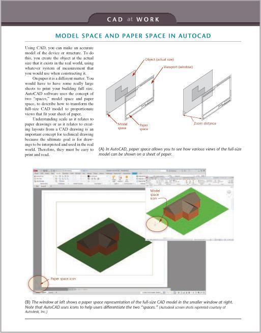
CADatWorkThis breakout page includes tips related to using the 2D or 3D CAD model to generate drawings.
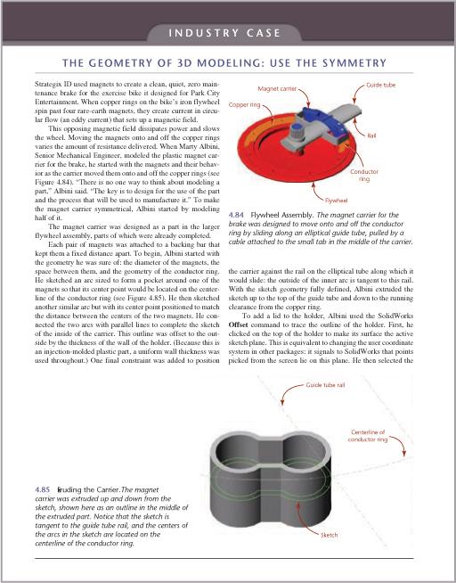
IndustryCase3D modeling practitioners share their best practices for modeling and documenting design.
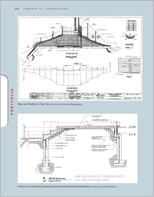
PortfolioExamples of finished drawings wrap up the chapter by showing real-world application of topics presented.
KeyWordsSet in bold italics on first reference, key words are summarized at the end of the chapter.
ChapterSummary
ReviewQuestions
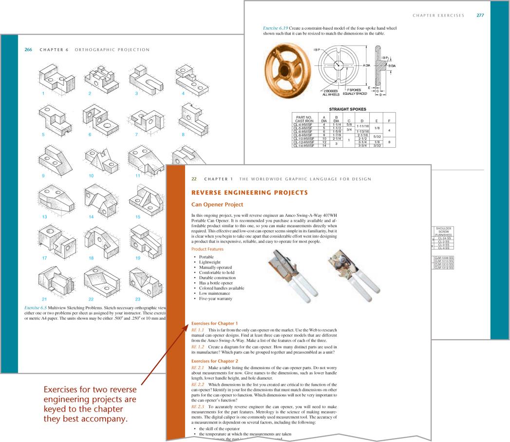
ChapterExercisesThe excellent Giesecke problem sets feature updated exercises, including plastic and sheet metal
parts, modeling exercises, assembly drawings from CAD models, and sketching problems.
The following features were designed to provide easy navigation and quick reference for students and professionals who look to Giesecke both as a helpfully-organized teaching text and a lasting reference.
Chapter Opener
“Spotlight” Sections
These sections add background information for key topics.
“Foundations” Section
This introductory section covers the chapter topic’s usage and importance, visualization tips, and theory related to the drawing and modeling techniques.
“Detail” Section
This is the “brass tacks” of the book, where detailed techniques, variations, and examples are organized into quick-read sections, numbered for easy reference.
“Step
by Step” Activities
Complicated processes are shown as step-by-step activities with each illustration right next to the text that explains it.
“Cad at Work”
CAD at Work sections break out examples related to using the 2D or 3D CAD model to generate drawings.
“Industry Case”
Several industry practitioners share their approaches to modeling and documenting design.
“Portfolio”
These pages offer examples of finished drawings showing real-world application of topics presented.
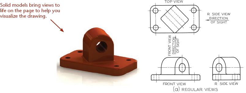
Solid Model Visualization Art
Illustrations
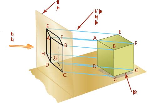
Colored callouts differentiate explanatory text from annotations in technical drawings. Consistent use of color helps differentiate the meaning of projection lines, fold lines, and other drawing elements. A color key is provided for easy reference.
Color Key for Instructional Art
Item In instructional art In a technical drawing
Callout arrow *
Dimension line a thin (0.3mm) black line
Projection line a lightly sketched line
Folding line used in descriptive geometry
Picture plane on edge
Plane of projection
Item In instructional art In a technical drawing
Cutting plane on edge (see Chapter 6)
Cutting plane *
Reference plane on edge used in descriptive geometry
Reference plane *
Viewing direction arrow
Horizon + ground line
Rotation arrow
* Not a typical feature of technical drawings. (Shown in this book for instructional purposes.)
Chapter Review
Each chapter ends with Key Words, a Chapter Summary, and Review Questions.
Chapter Exercises
The Giesecke problem sets feature updated exercises including plastic and sheet metal parts, constraint-based modeling, sketching problems, and reverse engineering projects.
Preface
For many decades, TechnicalDrawingwithEngineeringGraphicshas been recognized as an authority on the theories and techniques of graphics communication. Generations of instructors and students have used and retained this book as a professional reference. The long-standing success of Technical Drawing with Engineering Graphics can be attributed to its clear and engaging explanation of principles, and to its drawings, which are unsurpassed in detail and accuracy.
Although not a departure from its original authoritative nature and hallmark features, the book is thoroughly revised and updated to the latest technologies and practices in the field. With the addition of topics related to the role of the 3D CAD database in design and documentation, this sixteenth edition of Technical Drawing with EngineeringGraphicswill prepare students to enter the marketplace of the twenty-first century and continue to serve as a lasting reference.
Shawna Lockhart, contributing author since the ninth edition, first used Giesecke’s Technical Drawing when teaching engineering graphics at Montana State University. Throughout her 15 years as an award-winning professor, she selected this text because, in her words, “It was the most thorough and well-presented text with the best graphic references and exercises on the market.”
The quality of the illustrations and drawing examples was established by the original author, Frederick E. Giesecke, who created the majority of the illustrations in the first edition of TechnicalDrawing, published in 1933.
Giesecke, founder of the first formal architectural education program in Texas at what is today Texas A&M University, has been described as “a wunderkind of the first magnitude.” He joined the
A&M faculty at the age of 17, after graduating in 1886 with a B.S. in Mechanical Engineering, and by the age of 19, was appointed head of A&M’s Department of Mechanical Drawing. Having studied architectural drawing and design at Cornell University and the Massachusetts Institute of Technology, Giesecke also served as head of the Department of Architecture and the official college architect at Texas A&M, designing many campus buildings that are still standing today.
A long-time admirer of Giesecke’s legacy, Lockhart was honored to carry on the commitment to clear, engaging, thorough, and wellorganized presentation that began with the original author.
Lockhart is known as an early adopter and authority on CAD technologies. She is an instructor noted for outstanding dedication to students and for encouraging a broad spectrum of individuals, particularly women and minorities, to follow careers in engineeringrelated fields. Lockhart now works full time to ensure that the Giesecke graphics series continually applies to an evolving variety of technical disciplines.
Online Resources
An Instructor’s Manual (9780138065676) and Lecture Slides in PowerPoint format (9780138104405) are available on the companion site for this book at https://www.pearson.com/en-us/subjectcatalog/p/technical-drawing-with-engineeringgraphics/P200000009880.
Web chapters on axonometric projection and perspective drawing may be downloaded from www.peachpit.com. To access and download the bonus chapters:
1. Visit www.peachpit.com/techdrawing16e.
2. Log in with your Peachpit account, or if you don’t have one, create an account.