Contents
Contributors, vi
Preface, vii
1 Pacing and Defibrillation: Clinically Relevant Basics for Practice, 1
T. Jared Bunch, Suraj Kapa, David L. Hayes, Charles D. Swerdlow, Samuel J. Asirvatham, and Paul A. Friedman
2 Hemodynamics of Cardiac Pacing: Optimization and Programming to Enhance Cardiac Function, 39
Christ opher V. DeSimone, Joanna Gullickson, David L. Hayes, Paul A. Friedman, and Samuel J. Asirvatham
3 Indications for Pacemakers, Implantable Cardioverter‐Defibrillators, and Cardiac Resynchronization Therapy: Identifying Patients Who Benefit from Cardiac Rhythm Devices, 86
Krishna Kancharla, David L. Hayes, Samuel J. Asirvatham, and Paul A. Friedman
4 Choosing the Device Generator and Leads: Matching the Device with the Patient, 125
Christopher J. McLeod, Anca Chiriac, Malini Madhavan, David L. Hayes, Paul A. Friedman, and Samuel J. Asirvatham
5 Implanting and Extracting Cardiac Devices: Technique and Avoiding Complications, 149
Siva K. Mulpuru, Malini Madhavan, Samuel J. Asirvatham, Matthew J. Swale, David L. Hayes, and Paul A. Friedman
6 Implant‐Related Complications: Relevant Anatomy and Approaches for Prevention, 223 Niyada Naksuk, David L. Hayes, Paul A. Friedman, and Samuel J. Asirvatham
7 Timing Cycles, 263
David L. Hayes, Paul J. Wang, Samuel J. Asirvatham, and Paul A. Friedman
8 Programming: Maximizing Benefit and Minimizing Morbidity Programming, 325
Paul A. Friedman, Charles D. Swerdlow, Samuel J. Asirvatham, David L. Hayes, and Avi Sabbag
9 Sensor Technology for Rate‐Adaptive Pacing and Hemodynamic Optimization, 379
Krishna Kancharla, David L. Hayes, Samuel J. Asirvatham, and Paul A. Friedman
10 Troubleshooting, 399
Charles D. Swerdlow, Paul A. Friedman, Samuel J. Asirvatham, and David L. Hayes
11 Radiography of Implantable Devices, 514
David L. Hayes, Paul A. Friedman, and Samuel J. Asirvatham
12 Electromagnetic Interference: Sources, Recognition, and Management, 551
Subir Bhatia, Alan Sugrue, David L. Hayes, Paul A. Friedman, and Samuel J. Asirvatham
13 Follow‐up, 578
Alan Sugrue, Vaibhav R. Vaidya, David L. Hayes, Michael Glikson, Paul A. Friedman, and Samuel J. Asirvatham
Index, 620
Contributors
Samuel J. Asirvatham
Department of Cardiovascular Medicine, Division of Heart Rhythm Services, Mayo Clinic, Rochester, MN, USA
Subir Bhatia
Department of Cardiovascular Medicine, Division of Heart Rhythm Services, Mayo Clinic, Rochester, MN, USA
T. Jared Bunch
University of Utah, Salt Lake City, UT, USA
Anca Chiriac
Mayo Clinic, Jacksonville, FL, USA
Christopher V. DeSimone
Department of Cardiovascular Medicine, Division of Heart Rhythm Services, Mayo Clinic, Rochester, MN, USA
Paul A. Friedman
Department of Cardiovascular Medicine, Division of Heart Rhythm Services, Mayo Clinic, Rochester, MN, USA
Michael Glikson
Davidai Arrhythmia Center, Sheba Medical Center and Tel Aviv University, Tel Hashomer, Israel
Joanna Gullickson
Department of Cardiovascular Medicine, Division of Heart Rhythm Services, Mayo Clinic, Rochester, MN, USA
David L. Hayes
Department of Cardiovascular Medicine, Division of Heart Rhythm Services, Mayo Clinic, Rochester, MN, USA
Krishna Kancharla
University of Pittsburgh, UPMC, Pittsburgh, PA, USA
Suraj Kapa
Department of Cardiovascular Medicine, Division of Heart Rhythm Services, Mayo Clinic, Rochester, MN, USA
Malini Madhavan
Department of Cardiovascular Medicine, Division of Heart Rhythm Services, Mayo Clinic, Rochester, MN, USA
Christopher J. McLeod
Department of Cardiovascular Medicine, Division of Heart Rhythm Services, Mayo Clinic, Rochester, MN, USA; and Mayo Clinic, Jacksonville, FL, USA
Siva K. Mulpuru
Department of Cardiovascular Medicine, Division of Heart Rhythm Services, Mayo Clinic, Rochester, MN, USA
Niyada Naksuk
Division of Cardiovascular Medicine, Department of Internal Medicine, University of Nebraska Medical Center, Omaha, NE, USA
Avi Sabbag
Department of Cardiovascular Medicine, Division of Heart Rhythm Services, Mayo Clinic, Rochester, MN, USA
Alan Sugrue
Department of Cardiovascular Medicine, Division of Heart Rhythm Services, Mayo Clinic, Rochester, MN, USA
Matthew J. Swale
Department of Cardiovascular Medicine, Division of Heart Rhythm Services, Mayo Clinic, Rochester, MN, USA
Charles D. Swerdlow
Cedars‐Sinai Heart Center at Cedars‐Sinai Medical Center, Los Angeles, CA, USA; and David Geffen School of Medicine, University of California, Los Angeles, CA, USA
Vaibhav R. Vaidya
Department of Cardiovascular Medicine, Division of Heart Rhythm Services, Mayo Clinic, Rochester, MN, USA
Paul J. Wang
Stanford School of Medicine, Stanford University, Stanford, CA, USA
Preface
In many ways, this textbook mirrors the development of the field of cardiac device placement and management. The original version of this text was written by Drs. Seymour Furman, David Hayes, and David Holmes, pioneers and founders of interventional electrophysiology and device management. The goals of the present text remain similar to the original intent; that is, to provide a relatable, practical approach without ignoring the rigors of fundamental principles while retaining the flexibility in the professional’s mind to embrace new technology. Updates on resynchronization therapy, subcutaneous defibrillators, leadless devices, and improvements in lead extraction have been included in this text.
We continue to stay away from an encyclopedic approach, rather focusing on a usable, practical, and intuitive approach for problem solving in the day‐to‐day practice of a cardiac electrophysiology professional.
As with all prior editions, we owe a great debt of gratitude to all of the contributors who have tirelessly updated their sections and have done multiple revisions. We also
have to thank our patients and nursing staff who provide us with material to allow us to learn to a point where we can try and teach troubleshooting approaches, and so on. We received tremendous support from various device manufacturers, their engineers, and their published data material. These include assistance from Biotronik, Boston Scientific, Medtronic, and Abbott Medical.
The greatest challenge of our field is how to marry basic principles to tremendous change that is hard to predict. We hope that, through the core of this text, information and approaches to allow meaningful clarity in principles but with the ability to understand what is new and needed will be seen; and most important, we definitely hope that this text will help you in the day‐to‐day management of patients, improving outcomes and maximizing safety.
Samuel J. Asirvatham
David L. Hayes
Paul A. Friedman
1 Pacing and Defibrillation: Clinically Relevant Basics for Practice
T. Jared Bunch1, Suraj Kapa2, David L. Hayes2, Charles D. Swerdlow3,4, Samuel J. Asirvatham2, and Paul A. Friedman2
1 University of Utah, Salt Lake City, UT, USA
2 Department of Cardiovascular Medicine, Division of Heart Rhythm Services, Mayo Clinic, Rochester, MN, USA
3 Cedars‐Sinai Heart Center at Cedars‐Sinai Medical Center, Los Angeles, CA, USA
4 David Geffen School of Medicine, University of California, Los Angeles, CA, USA
Anatomy and physiology of the cardiac conduction system 2
Electrophysiology of myocardial stimulation 2
Pacing basics 4
Stimulation threshold 4
Variations in stimulation threshold 6
Clinical considerations when considering threshold 7
Threshold‐specific programming 8
Sensing 8
Sensing‐specific programming 10
Lead design 10
Bipolar and unipolar pacing and sensing 13
Left ventricular and His bundle pacing leads 14
Epicardial leads 15
Defibrillator leads – special considerations 15
Leadless pacemakers 15
Pulse generators 16
Pacemaker nomenclature 17
Essentials of defibrillation 18
Critical mass 19
Upper limit of vulnerability 19
Progressive depolarization 20
Virtual electrode depolarization 20
Electroporation as a mechanism for defibrillation 22
Defibrillation theory summary 23
The importance of waveform 23
Biphasic waveforms 24
Phase duration and tilt 25
Polarity and biphasic waveforms 25
Mechanism of improved efficacy with biphasic waveforms 25
Measuring shock dose 26
Measuring the efficacy of defibrillation 26
Threshold and dose–response curve 26
Relationship between defibrillation threshold and dose–response curve 26
Patient‐specific defibrillation threshold and safety margin testing – clinical indications 28
Management of the patient who fails defibrillation testing 29
Upper limit of vulnerability to assess safety margin 33
Practical implications of defibrillator therapies 33
Drugs and defibrillators 33
Antitachycardia pacing 33
Summary 34
References 34
Cardiac Pacing, Defibrillation and Resynchronization: A Clinical Approach, Fourth Edition. Edited by Samuel J. Asirvatham, Paul A. Friedman and David L. Hayes. © 2021 Mayo Foundation for Medical Education and Research. Published 2021 by John Wiley & Sons Ltd.
Anatomy and physiology of the cardiac conduction system
The cardiac conduction system consists of specialized tissue involved in the generation and conduction of electrical impulses throughout the heart. Knowledge of the normal anatomy and physiology of the cardiac conduction system is critical to understanding appropriate utilization of device therapy.
The sinoatrial (SA) node, located at the junction of the right atrium and the superior vena cava, is normally the site of impulse generation (Fig. 1.1). The SA node is composed of a dense collagen matrix containing a variety of cells. The large, centrally located P cells are thought to be the origin of electrical impulses in the SA node, which is surrounded by transitional cells and fiber tracts extending through the perinodal area into the remainder of the right atrium. The SA node is richly innervated by the autonomic nervous system, which has a key function in heart rate regulation. Specialized fibers, such as Bachmann’s bundle, conduct impulses throughout the right and left atria. The SA node has the highest rate of spontaneous depolarization and under normal circumstances is responsible for generating most impulses. Atrial depolarization is seen as the P wave on the surface electrocardiogram (ECG; Fig. 1.1).
Atrial conduction fibers converge, forming multiple inputs into the atrioventricular (AV) node, a small subendocardial structure located within the interatrial septum (Fig. 1.1). The AV node also receives abundant autonomic innervation, and it is histologically similar to the SA node because it is composed of a loose collagen matrix in which P cells and transitional cells are located. Additionally, Purkinje cells and myocardial contractile fibers may be found. The AV node allows for physiologic delay between atrial and ventricular contraction, resulting in optimal cardiac hemodynamic function. It can also function as a subsidiary “pacemaker” should the SA node fail. Finally, the AV node functions (albeit typically suboptimally) to regulate the number of impulses eventually reaching the ventricle in instances of atrial tachyarrhythmia. On the surface ECG, the majority of the PR interval is represented by propagation through the AV node and through the His–Purkinje fibers (Fig. 1.1).
Purkinje fibers emerge from the distal AV node to form the bundle of His, which runs through the membranous septum to the crest of the muscular septum, where it divides into the various bundle branches. The bundle branch system exhibits significant individual variation. The right bundle is typically a discrete structure running along the right side of the interventricular septum to the moderator band, where it divides. The left bundle is usually a large band of fibers fanning out over
the left ventricle, forming functional fascicles. Both bundles eventually terminate in individual Purkinje fibers interdigitating with myocardial contractile fibers. The His–Purkinje system has correspondingly less autonomic innervation than the SA and AV nodes.
Because of their key function and location, the SA and AV nodes are the most common sites of conduction system failure; it is understandable, therefore, that the most common indications for pacemaker implantation are SA node dysfunction and high‐grade AV block. It should be noted, however, that conduction system disease is frequently diffuse and may involve the specialized conduction system at multiple sites.
Electrophysiology of myocardial stimulation
Stimulation of the myocardium requires initiation of a propagating wave of depolarization from the site of initial activation, whether from a native “pacemaker” or from an artificial stimulus. Myocardium exhibits “excitability,” which is a response to a stimulus out of proportion to the strength of that stimulus.1 Excitability is maintained by separation of chemical charge, which results in an electrical transmembrane potential. In cardiac myocytes, this electrochemical gradient is created by differing intracellular and extracellular concentrations of sodium (Na+) and potassium (K+) ions; Na+ ions predominate extracellularly, and K+ ions predominate intracellularly. Although this transmembrane gradient is maintained by the high chemical resistance intrinsic to the lipid bilayer of the cellular membrane, passive leakage of these ions occurs across the cellular membrane through ion channels. Passive leakage is offset by two active transport mechanisms, each transporting three positive charges out of the myocyte in exchange for two positive charges that are moved into the myocyte, producing cellular polarization.2,3 These active transport mechanisms require energy and are susceptible to disruption when energy‐generating processes are interrupted.
The chemical gradient has a key role in the generation of the transmembrane action potential (Fig. 1.2). The membrane potential of approximately −90 mV drifts upward to the threshold potential of approximately −70 to −60 mV. At this point, specialized membrane‐bound channels modify their conformation from an inactive to an active state, which allows the abrupt influx of extracellular Na + ions into the myocyte,4,5 creating phase 0 of the action potential and rapidly raising the transmembrane potential to approximately +20 mV.6,7 This rapid upstroke creates a short period of overshoot potential (phase 1), which is followed by a plateau period (phase 2) created by the

Fig. 1.1 (A) The cardiac conduction system. AV, atrioventricular; SA, sinoatrial. Conduction begins with impulse generation in the SA node (left panel). Impulse propagation through the atria gives rise to the P wave on the surface electrocardiogram (ECG; bottom of left panel). The impulse is then delayed in the AV node to allow blood to flow to the ventricles; wave‐front travel through the AV node is not seen on the surface ECG. The wave fronts then pass through the His–Purkinje system, to rapidly activate the ventricular myocardium. The larger mass of the ventricles give rise to the large‐amplitude QRS complex. Further details in text. (B) An anatomic specimen showing the location of key conduction system elements. The top panel shows an external view of the heart with the region of the SA node in the epicardium at the juncture of the superior vena cava (SVC) and right atrium indicated. The structure itself is not visible to the naked eye.
IVC, inferior vena cava. In the bottom panel, the right atrial and ventricular free wall have been removed to reveal the position of the AV node anterior to the coronary sinus (CS) and atrial to the tricuspid valve (TV), situated in Koch’s triangle (bounded by the TV, CS, and tendon of Todaro, not shown). FO, fossa ovalis; RAA, right atrial appendage.
SA Node
(B)
AV Node
His bundle
Left bundle
Right bundle

inward calcium (Ca2+) and Na+ currents balanced against outward K+ currents.8–10 During phase 3 of the action potential, the transmembrane potential returns to normal, and during phase 4 the gradual upward drift in transmembrane potential repeats. The shape of the transmembrane potential and the relative distribution of the various membrane‐bound ion channels differ between the components of the specialized cardiac conduction system and working myocytes, allowing for their differing regional purposes and functions. Depolarization of neighboring cells occurs as a result of passive conduction via low‐resistance intercellular connections called “gap junctions,” with active regeneration along cellular membranes.11,12 The velocity of depolarization throughout the myocardium depends on the speed of depolarization of the various cellular components of the myocardium and on the geometric arrangement and orientation of the myocytes. Factors such as myocardial ischemia, electrolyte imbalance, metabolic abnormalities, myocardial scar, diseased tissue, and drugs affect depolarization and depolarization velocity.
Pacing basics
Understanding cardiac pacing requires an intimate consideration of two key elements: stimulation threshold (i.e., the minimum amount of output required to stimulate a sufficient quantity of cells so as to facilitate initiation of a propagating impulse) and sensing (i.e., the ability of a device to detect a propagating impulse amidst the cellular milieu). These elements are facilitated by a variety of factors related to lead design, interface between leads and myocardial tissue, and other factors, as outlined later in this chapter.
Fig. 1.2 Action potential of a typical Purkinje fiber, with the various phases of depolarization and repolarization (described in the text). (Source: From Stokes KB, Kay GN. Artificial electric cardiac stimulation. In: Ellenbogen KA, Kay GN, Wilkoff BL, eds. Clinical Cardiac Pacing. Philadelphia: WB Saunders Co., 1995: 3–37, by permission of the publisher.)
Stimulation threshold
Artificial pacing involves delivery of an electrical impulse from an electrode of sufficient strength to cause depolarization of the myocardium in contact with that electrode and propagation of that depolarization to the rest of the myocardium. The minimal amount of energy required to produce this depolarization is called the stimulation threshold. The components of the stimulus include the pulse amplitude (measured in volts) and the pulse duration (measured in milliseconds). An exponential relationship exists between the stimulus amplitude and the duration, resulting in a hyperbolic strength–duration curve. At short pulse durations, a small change in the pulse duration is associated with a significant change in the pulse amplitude required to achieve myocardial depolarization; conversely, at long pulse durations, a small change in pulse duration has relatively little effect on threshold amplitude (Fig. 1.3). Two points on the strength–duration curve should be noted (Fig. 1.4). The rheobase is defined as the smallest amplitude (voltage) that stimulates the myocardium at an infinitely long pulse duration (milliseconds). The chronaxie is the threshold pulse duration at twice the rheobase voltage. The chronaxie is important in the clinical practice of pacing because it approximates the point of minimum threshold energy (microjoules) required for myocardial depolarization.
The relationship of voltage, current, and pulse duration to stimulus energy is described by the formula
Fig. 1.3 Relationship of charge, energy, voltage, and current to pulse duration at stimulation threshold. As the pulse duration is shortened, voltage and current requirements increase. Charge decreases as pulse duration shortens. At threshold, energy is lowest at a pulse duration of 0.5–1.0 ms and increases at pulse widths of shorter and longer duration. (Source: Modified from Furman S. Basic concepts. In: Furman S, Hayes DL, Holmes DR Jr, eds. A Practice of Cardiac Pacing. Mount Kisco, NY: Futura Publishing Co., by permission of the publisher.)
Energy in microjoules
Current in milliamperes
Fig. 1.4 Relationships among chronic ventricular strength–duration curves from a canine, expressed as potential (V), charge (μC), and energy (μJ). Rheobase is the threshold at infinitely long pulse duration. Chronaxie is the pulse duration at twice rheobase. (Source: From Stokes K, Bornzin G. The electrode–biointerface stimulation. In: Barold SS, ed. Modern Cardiac Pacing. Mount Kisco, NY: Futura Publishing Co., 1985: 33–77, by permission of the publisher.)

in which E is the stimulus energy, V is the voltage, R is the total pacing impedance, and t is the pulse duration. This formula demonstrates the relative increase in energy with longer pulse durations. The energy increase due to duration is offset by a decrement in the voltage needed. The strength–duration curve discussed thus far has been that of a constant‐voltage system, which is used in all current pacemakers and defibrillators. Constant‐current devices are no longer used. The singular exception to this is biologic pacemakers, which allow for use of cells repurposed to recreate the body’s intrinsic conduction system. However, this approach is not presently available for human use and thus will not be discussed here.
Impedance is the term applied to the resistance to current flow in the pacing system. Ohm’s law describes the relationship among voltage, current, and resistance as VIR
in which V is the voltage, I is the current, and R is the resistance. Although Ohm’s law is used for determining impedance, the impedance and resistance are technically not interchangeable terms. Impedance implies inclusion of all factors that contribute to current flow impediment, including lead conductor resistance, electrode resistance, resistance due to electrode polarization, capacitance, and inductance. Technically, the term “resistance” does not include the effects of capacitance
(storage of charge) or inductance (storage of current flow) to impede current flow. Nevertheless, Ohm’s law (substituting impedance for R) is commonly used for calculating impedance. In constant‐voltage systems, the lower the pacing impedance, the greater the current flow; conversely, the higher the pacing impedance, the lower the current flow. Lead conductors are designed to have a low resistance to minimize the generation of energy‐wasting heat as current flows along the lead, and electrodes are designed to have a high resistance to minimize current flow and to have negligible electrode polarization. Decreasing the electrode radius minimizes current flow by providing greater electrode resistance and increased current density, resulting in greater battery longevity and lower stimulation thresholds.13
“Polarization” refers to layers of oppositely charged ions that surround the electrode during the pulse stimulus. It is related to the movement of positively charged ions (Na+ and H3O+) to the cathode; the layer of positively charged ions is then surrounded by a layer of negatively charged ions (Cl , HPO42−, and OH ). These layers of charge develop during the pulse stimulus, reaching peak formation at the termination of the pulse stimulus, after which they gradually dissipate. Polarization impedes the movement of charge from the electrode to the myocardium, resulting in a need for increased voltage for stimulation. As polarization develops with increasing pulse duration, one way to combat formation of polarization is to shorten the pulse duration. Electrode design has incorporated the use of
materials that minimize polarization, such as platinum black, iridium oxide, titanium nitride, and activated carbon.14 Finally, polarization is inversely related to the surface area of the electrode. To maximize the surface area (to reduce polarization) but minimize the radius (to increase electrode impedance), electrode design incorporates a small radius but a porous, irregular surface construction.15 Fractal coatings on the lead tip increase the surface area 1000‐fold without the need to increase the axial diameter. Leads designed to maximize these principles are considered “high‐impedance” leads.
Variations in stimulation threshold
Myocardial thresholds typically fluctuate, occasionally dramatically, during the first weeks after implantation. After implantation of earlier generations of endocardial leads, the stimulation threshold would typically rise rapidly in the first 24 h and then gradually increase to a peak at approximately 1 week (Fig. 1.5). Over the ensuing 6–8 weeks, the stimulation threshold would usually decline to a level somewhat higher than that at implantation, but less than the peak threshold, known as the “chronic threshold.”16,17 The magnitude and duration of this early increase in threshold was highly dependent on lead design, the interface between the electrode and the myocardium, and individual patient variation, but chronic thresholds would typically be reached by 3 months. The single most important lead design change to alter pacing threshold evolution was the incorporation of steroid elution at the lead tip, to blunt the local inflammatory response (Fig. 1.6). With steroid

Fig. 1.5 Long‐term pacing thresholds from a conventional lead (CL; no steroid elution) and a steroid‐eluting lead (ST). With the conventional lead, an early increase in threshold decreases to a plateau at approximately 4 weeks. The threshold for the steroid‐eluting lead remains relatively flat, with no significant change from short‐term threshold measurements. (Source: From Furman S. Basic concepts. In: Furman S, Hayes DL, Holmes DR Jr, eds. A Practice of Cardiac Pacing, 2nd edn. Mount Kisco, NY: Futura Publishing Co., 1989: 23–78, by permission of Mayo Foundation.)
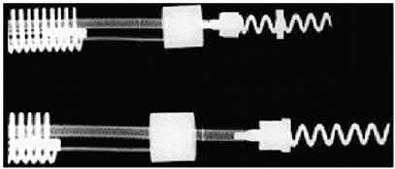
Fig. 1.6 Diagram of a steroid‐eluting active fixation lead. The electrode has a porous, platinized tip. A silicone rubber collar is impregnated with 1 mg of dexamethasone sodium.
Extendable/ retractable helix
Steroid eluting collar
elution there may be a slight increase in thresholds postimplantation, with subsequent reduction to almost that of acute thresholds.18,19
Transvenous pacing leads have used passive or active fixation mechanisms to provide a stable electrode–myocardium interface. Active fixation leads may have higher initial pacing thresholds acutely at implantation, but thresholds frequently decline significantly within the first 5–30 min after placement.16 This effect has been attributed to hyperacute injury due to advancement of the screw into the myocardium. On a cellular level, implantation of a transvenous pacing lead results in acute injury to cellular membranes, which is followed by the development of myocardial edema and coating of the electrode surface with platelets and fibrin. Subsequently, various chemotactic factors are released, and an acute inflammatory reaction develops, consisting of mononuclear cells and polymorphonuclear leukocytes. After the acute response, release of proteolytic enzymes and oxygen free radicals by invading macrophages accelerates cellular injury. Finally, fibroblasts in the myocardium begin producing collagen, leading to production of the fibrotic capsule surrounding the electrode. This fibrous capsule ultimately increases the effective radius of the electrode, with a smaller increase in surface area.20,21 Steroid‐eluting leads are believed to minimize fibrous capsule formation. In both atrial and ventricular active fixation leads, steroid elution results in long‐term reduction in energy consumption with maintenance of stimulation thresholds, lead impedance values, and sensing thresholds.22,23
The stimulation threshold may vary slightly with a circadian pattern, generally increasing during sleep and decreasing during the day, probably reflecting changes in autonomic tone. The stimulation threshold may also rise after eating; during hyperglycemia, hypoxemia, or acute viral illnesses; or as a result of electrolyte fluctuations. In general, these threshold changes are minimal. However, in the setting of severe hypoxemia or electrolyte abnormalities they can lead to loss of capture. Certain drugs used in patients with cardiac disease may also increase pacing thresholds – see Chapter 8
(Programming: Maximizing Benefit and Minimizing Morbidity Programming).
The inflammatory reaction and subsequent fibrosis that occur after lead implantation may act as an insulating shield around the electrode. These processes effectively increase the distance between the electrode and the excitable tissue, allowing the stimulus to disperse partially before reaching the excitable cells. These changes result in an increased threshold for stimulation and attenuate the amplitude and slew rate of the endocardial signal being sensed. This is a process termed “lead maturation.” Improvements in electrode design and materials have reduced the severity of the inflammatory reaction and, thus, improved lead maturation rates.18,24 When the capture threshold exceeds the programmed output of the pacemaker, exit block will occur; loss of capture will result if the capture threshold exceeds the programmed output of the pacemaker.16,25 Exit block, a consequence of lead maturation, results from the progressive rise in thresholds over time.16,25 This phenomenon occurs despite initial satisfactory lead placement and implantation thresholds, often but not always occurs in parallel in the atrium and ventricle, and usually recurs with placement of subsequent leads. Steroid‐eluting leads prevent exit block in most, but not all, patients (Fig. 1.6).
Clinical considerations when considering threshold
Several clinical considerations are needed when evaluating stimulation threshold and using this to guide programming of the device. One key consideration is that of cathodal versus anodal stimulation and how this relates to local myocardial capture. In cathodal stimulation, electrons “enter” the muscle from the electrode, resulting in relatively low capture thresholds and minimal electrode corrosion. Specifically, capture occurs at the tip electrode. During anodal stimulation, myocardial capture occurs at the anode, which, in bipolar pacing configurations in which both cathode and anode are in contact with myocardium, generally occurs at the level
of the ring electrode. Capture during cathodal stimulation occurs at the onset of the impulse (or the leading edge). In turn, anodal stimulation occurs at the trailing edge of the stimulus. One key issue with anodal stimulation is that the resulting myocardial refractory period tends to be shorter, and one particular concern (particularly at faster heart rates) is an R‐on‐T phenomenon that could result in ventricular fibrillation (VF). Risk of anodal stimulation is minimized by making the anode as large as possible to reduce electron density.
The clinical area in which anodal stimulation is of particular importance in modern pacing systems is cardiac resynchronization devices. This is of specific importance in cases where resynchronization devices are set to pace from the tip of the left ventricular lead (cathode) to the right ventricular (RV) ring (anode). This pacing modality is often used when phrenic pacing is present during bipolar left ventricular lead pacing. At higher outputs, it is possible to have anodal stimulation from the RV ring, in which case three wave fronts are possible: one from the left ventricular tip (cathodal, left ventricle paced), one from the RV tip (cathodal, right ventricle paced), and one from the RVr ring (anodal). These three wave fronts can result in less than desirable pacing, resulting in nonresponse to resynchronization. The risk of this is minimized by using an integrated RV lead, where the shocking coil is the ring electrode, making anodal capture extremely unlikely due to the large surface area of the anode.
Threshold‐specific programming
The threshold defines specific safety margins for programming of a device. Specifically, by understanding the minimum output needed to consistently capture the myocardium, one can program a device at a level that will ideally consistently capture myocardium even if thresholds change for reasons described previously. Generally, at the time of initial implant, programming at a relatively high output (as much as five times the threshold) may be considered. However, this may be limited by higher initial thresholds. Over chronic use, when it is felt threshold has more or less stabilized, programming a two times safety factor above the stimulation threshold may be reasonable. As already described above, however, one key consideration is the risk of anodal stimulation in resynchronization devices. Programming too‐high outputs based on stimulation thresholds may be guided by anodal stimulation seen at higher outputs, or even the potential for capture of surrounding tissues of interest (phrenic nerve, diaphragm, etc.). Thus, a stimulation threshold may be considered in both directions: the minimum output at which the myocardium is captured, and the maximum output at which undesirable capture of surrounding tissues or
anodal stimulation may occur. Programming of a device would thus require consideration of these lower and upper thresholds while simultaneously allowing for a sufficient safety margin. It should also be noted that programmed output of pacing at the time of initial device implant (when it cannot be certain how the threshold will stabilize), at the time of chronic follow‐up (when it may be hoped that thresholds are more or less stabilized), and when considering the clinical situation at the time of pacing is critical. In the last scenario, one can specifically consider the situation of postdefibrillation pacing, when stimulation thresholds may be increased due to tissue ischemia during the preceding tachyarrhythmia or at the time of defibrillation.
Sensing
The first pacemakers functioned as fixed‐rate, VOO devices. All contemporary devices offer demand‐mode pacing, which pace only when the intrinsic rate is below the programmed rate. For such devices to function as programmed, accurate and consistent sensing of the native rhythm are essential.
Intrinsic cardiac electrical signals are produced by the wave of electrical current through the myocardium (Fig. 1.7). As the wave front of electrical energy approaches an endocardial unipolar electrode, the intracardiac electrogram records a positive deflection. As the wave front passes directly under the electrode, a sharp negative deflection is recorded, referred to as the intrinsic deflection.26 The intrinsic deflection is inscribed as the advancing wave front passes directly underneath a unipolar electrode. Smaller positive and negative deflections preceding and following the intrinsic deflection represent activation of surrounding myocardium. The analog on the surface ECG is the peak of the R wave, referred to as the intrinsicoid deflection, because the electrical depolarization is measured at a distance (from the surface), rather than directly on the myocardium. However, the intrinsic deflection is a local endocardial event; it does not necessarily time with the intrinsicoid deflection in any ECG lead. Bipolar electrograms (Fig. 1.7) represent the difference in potential recorded between two closely spaced intracardiac electrodes. Owing to the close spacing of two typically small electrodes, far‐field signals (i.e., signals not generated by the tissue the lead electrode is in contact with) are smaller and thus more easily rejected by pacemakers and defibrillators. Ventricular electrograms typically are much larger than atrial electrograms because ventricular mass is greater. Typical amplitude ranges for ventricular electrograms are 5–25 mV, and for atrial electrograms 1.5–5 mV (Fig. 1.8). The maximum frequency densities of electrograms in sinus rhythm are in the range of 80–100 Hz in the atrium and 10–30 Hz in the ventricle (these frequencies


Fig. 1.7 Schema of the relationship of the pacing lead to the recorded electrogram with (A) unipolar and (B) bipolar sensing. (A) Top: as the electrical impulse moves toward the cathode (lead tip), a positive deflection is created in the electrogram. Middle: as the electrical impulse passes the cathode, the deflection suddenly moves downward, at the intrinsic deflection. Bottom: as the impulse moves away from the cathode, a negative deflection occurs. (B) The same phenomena occur for each electrode of a bipolar lead when considered independently (uni‐1 and uni‐2). When these are put together as a bipolar signal, the resultant tracing is seen at the bottom (bipolar 1–2). (Source: Adapted from Stevenson WG, Soejima K. Recording techniques for clinical electrophysiology. J Cardiovasc Electrophysiol 2005; 16:1–6.)
may differ slightly depending on leads and/or technologies). Pulse generator filtering systems are designed to attenuate signals outside these ranges. Filtering and use of blanking and refractory periods (discussed later) have markedly reduced unwanted sensing, although myopotential frequencies (ranging from 10 to 200 Hz) considerably overlap with those generated by atrial and ventricular depolarization and are difficult to filter out, especially during sensing in a unipolar configuration.27–29 Shortening of the tip‐to‐ring spacing has also improved atrial sensing and rejection of far‐field R waves.
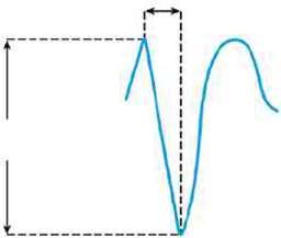
A second important metric of the intracardiac electrogram in addition to amplitude is the slew rate; that is, the peak slope of the developing electrogram30 (Fig. 1.8). The slew rate represents the maximal rate of change of the electrical potential between the sensing electrodes and is the first derivative of the electrogram (dV/dt).
An acceptable slew rate should be at least 0.5 V/s in both the atrium and the ventricle. In general, the higher the slew rate, the higher the frequency content and the more likely the signal will be sensed. Slow, broad signals, such as those generated by the T wave, are less likely to be sensed because of a low slew rate and lower frequency density.
(ΔT)
Sensing AtriumVentricle
Electrogram
Selw rate (v/s)
Fig. 1.8 In the intracardiac electrogram, the difference in voltage recorded between two electrodes is the amplitude, which is measured in millivolts. The slew rate is volts per second and should be at least 0.5.
Polarization also affects sensing function. After termination of the pulse stimulus, an excess of positive charge surrounds the cathode, which then decays until the cathode is electrically neutral. Afterpotentials can be sensed, resulting in inappropriate inhibition or delay
Uni-1
of the subsequent pacing pulse (Fig. 1.9). The amplitude of afterpotentials is directly related to both the amplitude and the duration of the pacing pulse; thus, they are most likely to be sensed when the pacemaker is programmed to high voltage and long pulse duration in combination with maximal sensitivity.30 The use of programmable sensing refractory and blanking periods has helped to prevent the pacemaker from reacting to afterpotentials, although, in dual‐chamber systems, atrial afterpotentials of sufficient strength and duration to be sensed by the ventricular channel may result in inappropriate ventricular inhibition (crosstalk), especially in unipolar systems.31,32 Afterpotentials may be a source of problems in devices with automatic threshold measurement and capture detection; the use of leads designed to minimize afterpotentials may increase the effectiveness of such algorithms.33
“Source impedance” is the impedance from the heart to the proximal portion of the lead, and it results in a voltage drop from the site of the origin of the intracardiac electrogram to the proximal portion of the lead.34
Components include the resistance between the electrode and the myocardium, the resistance of the lead conductor material, and the effects of polarization. The resistance between the electrode and the myocardium, as well as polarization, is inversely related to the surface
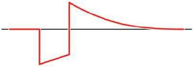
Afterpotential
Trailing edge
Leading edge
1.9 Diagram of a pacing pulse, constant voltage, with leading edge and trailing edge voltage and an afterpotential with opposite polarity. As described in the text, afterpotentials may result in sensing abnormalities.
area of the electrode; thus, the effects of both can be minimized by a large electrode surface area. The electrogram actually seen by the pulse generator is determined by the ratio between the sensing amplifier (input) impedance and the lead (source) impedance. Less attenuation of the signal from the myocardium occurs when there is a greater ratio of input impedance to source impedance. Clinically, impedance mismatch is seen with insulation or conductor failure, which results in sensing abnormalities or failure.
Sensing‐specific programming
When programming the sensitivity of the device, it is important to consider the rhythm being sensed as well as the desire to marry avoidance of oversensing of nonmyocardial signals or myocardial signals beyond the chamber of interest as well as undersensing of signals within the chamber of interest. When evaluating sensing, it is of particular importance to consider the rhythm being sensed. For example, local atrial or ventricular signals may have higher amplitudes during normal rhythm than during an arrhythmia, such as atrial fibrillation or VF. Thus, appropriate sensing during periods of arrhythmia may require greater sensitivity settings. In turn, oversensing of ancillary phenomena (repolarization during ventricular sensing, ventricular signals during atrial sensing) may result in inappropriate withholding or delivery of therapies. Thus, a balance in sensitivity settings is often required.
Lead design
Traditional pacing lead components include the electrode and fixation device, the conductor, the insulation, and the connector pin (Figs 1.10 and 1.11). However, novel device and lead designs, allowing for leadless pacemakers and other novel approaches to cardiac stimulation, afford different form factors that, nevertheless, rely on similar principles to traditional leads.
1.10 (A) Basic components of a passive fixation pacing lead with tines. (B) Active fixation lead in which the helix serves as the distal electrode.
Fig.
Fig.
Leads are subject to biologic, chemical, and mechanical repetitive stress. They must be constructed of materials that provide mechanical longevity, stability, and flexibility; they must satisfy electrical conductive and resistive requirements; they must be insulated with material that is durable and that has a low friction coefficient, to facilitate implantation; and they must include an electrode that provides good mechanical and electrical contact with the myocardium. Industry continues to improve lead design to achieve these goals.
Optimal stimulation and sensing thresholds favor an electrode with a small radius and a large surface area. Electrode shape and surface composition have evolved
over time. Early models utilized a round, spherical shape with a smooth metal surface. Electrodes with an irregular, textured surface allow for increased surface area without an increase in electrode radius. 15,33,35 To achieve increased electrode surface area, manufacturers have used a variety of designs, including microscopic pores, coatings of microspheres, and wire filament mesh.
Unfortunately, relatively few conductive materials have proven to be satisfactory for use in pacing electrodes. Ideally, electrodes are biologically inert, resist degradation over time, and do not elicit a marked tissue reaction at the myocardium–electrode interface. Certain metals, such as zinc, copper, mercury, nickel, lead, and silver, are associated with toxic reactions with the myocardium. Stainless steel alloys are susceptible to corrosion. Titanium, tantalum, platinum, and iridium acquire a surface coating of oxides that impedes current transfer. Materials currently in use are platinum–iridium, platinized titanium‐coated platinum, iridium oxide, and platinum (Fig. 1.12). Carbon electrodes seem to be least susceptible to corrosion. Also, they are improved by activation, which roughens the surface to increase the surface area and allow for tissue ingrowth.36
Lead fixation with traditional leads may be active or passive. Passive fixation endocardial leads usually incorporate tines at the tip that become ensnared in
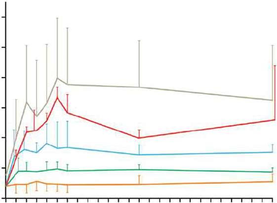
12 34 56 13 20 26
Implant time (weeks)
1.12 Capture thresholds from implantation to 26 weeks from a variety of unipolar leads with similar geometric surface area electrodes. From top to bottom, the curves represent laser drilled polished platinum; porous surface platinum; activated carbon; platinized target tip; and porous steroid eluting leads. (Source: From Stokes KB, Kay GN. Artificial electric cardiac stimulation. In: Ellenbogen KA, Kay GN, Wilkoff BL, eds. Clinical Cardiac Pacing. Philadelphia: WB Saunders Co., 1995: 3–37, by permission of the publisher.)
Fig. 1.11 Radiographic example of an active fixation screw‐in lead with a retractable screw rather than a screw that is always extended. The screw is extended in the lower image.
Fig.
trabeculated tissue in the right atrium or ventricle, providing lead stability. Leads designed for coronary venous placement usually incorporate a design that wedges the lead against the wall of the coronary vein. Active fixation leads deploy an electrically active screw into the myocardium to provide lead stability. There are advantages and disadvantages to active and passive designs. Passive fixation leads are simple to deploy. However, considerable myocardial and fibrous tissue enveloping the tip typically develops with passive fixation leads. The encasement of the tines of a passive fixation lead by fibrous tissue often makes the extraction of passive fixation leads more difficult than that of active fixation leads. Active fixation leads are often preferable in patients with distorted anatomy, such as those with congenital cardiac defects or those with surgically amputated atrial appendages. Active fixation leads are also preferable in patients with high right‐sided pressures. As alternative site pacing has evolved (i.e., the placements of leads outside the right atrial appendage and RV apex), screw‐in leads have become more popular because of the ability to stabilize them mechanically in nontraditional locations.
In active fixation leads, various mechanism are used to keep the screw unexposed (to avoid tissue injury) until it is in position for fixation. In many leads, the helix is extendable and retractable by rotation of the proximal connector using a simple tool (Bisping screwdriver). This allows the operator to control the precise time and location of helix deployment. Another approach entails covering a fixed helix with a material such as mannitol which dissolves in the bloodstream after approximately 5 min. This permits placement of the lead atraumatically at the desired location. Fixation is accomplished by rotating the entire lead body.
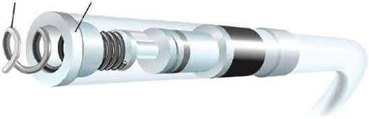
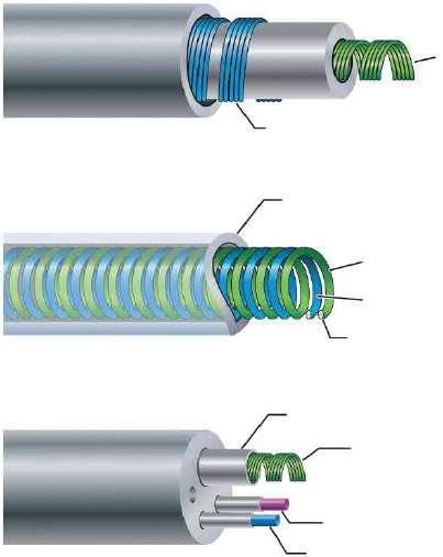
Conductors are commonly of a multifilament design to provide tensile strength and reduce resistance to metal fatigue (Fig. 1.13). Alloys such as MP35N (cobalt, nickel, chromium, and molybdenum) and nickel silver are typically used in modern pacing leads. Bipolar leads may be of coaxial design, with an inner coil extending to the distal electrode and an outer coil terminating at the proximal electrode (Fig. 1.14). This design requires that the conductor coils be separated by a layer of inner insulation. Coaxial designs remain commonly used in the treatment of bradyarrhythmias. Some bipolar leads are coradial, or “parallel‐wound”; that is, two insulated coils are wound next to each other. Leads may also be constructed with the conductor coils parallel to each other (multiluminal), again separated by insulating material (Fig. 1.14). This type of design is typically used for tachyarrhythmia leads. Additionally, leads may use a combination of coils and cables. The coil facilitates the

1.13 Conductor coils may be of unifilar, multifilar, or cable design. The multifilar and cable designs allow the conductor to be more flexible and more resistant to fracture.
passage of a stylet for lead implantation, and the cable allows a smaller lead body.
Two materials have predominated in lead insulation: silicone and polyurethane. Each has its respective advantages and disadvantages, but the overall performances of both materials have been excellent.37
The two grades of polyurethane that have had the widest use are Pellathane 80A (P80A) and Pellathane 55D. Early after the introduction of polyurethane as an insulating material, it became clear that clinical failure rates with specific leads were higher than acceptable; further investigation revealed that the failures were occurring primarily in leads insulated with the P80A polymer.35,38 Microscopic cracks developed in the P80A polymer, initially occurring as the heated polymer cooled during manufacture; with additional environmental stress, these cracks propagated deeper into the insulation, resulting in failure of the lead insulation.
Polyurethane may also undergo oxidative stress in contact with conductors containing cobalt and silver chloride, resulting in degradation of the lead from the inside and subsequent lead failure. Some current leads use silicone with a polyurethane coating, incorporating the strength and durability of silicone with the ease of handling of polyurethane while maintaining a satisfactory external lead diameter. Silicone rubber is well known to be susceptible to abrasion wear, cold flow due to cyclic compression, and wear from lead‐to‐lead and lead‐to‐can contact. Current silicone leads have surface modifications that improve lubricity and reduce friction in blood. Preliminary studies have suggested that a hybrid coating of silicone and polyurethane may offer improved wear.39 Despite lead improvements, laboratory testing, and premarketing, clinical trials have been inadequate to predict the long‐term performance of
Unifilar
Fig.
Fig. 1.14 Varieties of conductor construction.
Top: bipolar coaxial design with an inner multifilar coil surrounded by insulation (inner), an outer multifilar coil, and outer insulation. Middle: individually insulated wires wound together in a single multifilar coil for bipolar pacing. Bottom: multilumen lead body design in which each conductor has its own lumen.
leads, so that clinicians implanting the devices or performing follow‐up in patients with pacing systems must vigilantly monitor lead status. Increasingly, the use of internet‐enabled remote monitoring and pulse‐generator‐based algorithms permits automatic alert generation in the event of impending lead fracture.
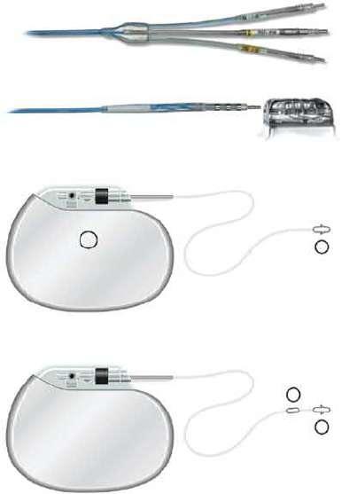
Contemporary leads and connectors are standardized to conform to international guidelines (IS‐1 standard), which mandate that leads have a 3.2 mm diameter in‐line bipolar connector pin.40 These standards were established many years ago because some leads and connector blocks were incompatible, requiring the development of multiple adaptors. The use of the IS‐1 standard permits using one manufacturer’s leads with another manufacturer’s pulse generator. Similarly, the DF‐1 standard insures a common site for high‐voltage connections in defibrillators. The newer IS‐4 standard permits a single in‐line connection of four low‐voltage electrodes, permitting coronary sinus leads to include four (rather than two) pacing sites, increasing the likelihood of a lead having an acceptable threshold and/or pacing site. The DF‐4 connectors (Fig. 1.15A) contain two high‐voltage and two low‐voltage connections so that a single connector (with single screw) can provide pace‐sense and dual coil defibrillation support, significantly decreasing pocket bulk. The limitation introduced by the DF‐4 connector is the inability to use a separate lead and connect it to the proximal coil port in
Tip electrode coil
Indifferent electrode coil
Other insulation
Tip electrode coil
Indifferent electrode coil
Integral insulation
Insulation
High voltage (defibrillation) conductor
Sensing conductor
Pacing conductor
the header. Though not commonly required, this is useful when the defibrillation threshold (DFT) is high and a strategy of placing a defibrillation coil in the coronary sinus, azygous vein, or subcutaneous tissues is planned.
Bipolar and unipolar pacing and sensing
In unipolar pacing systems, the lead tip functions as the cathode and the pulse generator as the anode (unipolar vs. bipolar leads; Fig. 1.15B). In bipolar systems, the lead tip serves as the cathode and a lead ring acts as the anode (Fig. 1.15B). Unipolar leads are of simpler design (only one conductor) and have a smaller external diameter. Unipolar leads have historically demonstrated greater durability than bipolar leads. In recent years, the difference in durability has been less distinct. Unipolar leads do not offer the option of bipolar function. Although unipolar and bipolar leads are readily available, present usage of transvenous leads is almost exclusively bipolar. Bipolar leads may function in the unipolar mode if the pacemaker is so programmed. They are available in several designs, generally coaxial or multiluminal. Regardless of design, the external diameter of a bipolar lead is usually greater than that of unipolar leads because each coil must be electrically separated by insulating material. Bipolar pacing is generally preferred over unipolar pacing because it rarely causes extracardiac stimulation at the pulse generator (pectoralis muscle stimulation), which may more often
Multilumen lead
Fig. 1.15 Lead connectors and configurations. (A) Connector types in defibrillator leads. The top image shows the proximal end of a defibrillation lead with three connectors. Top and bottom pins are DF‐1 connectors used for high‐voltage shock delivery for defibrillation, whereas the middle pin is an IS‐1 connector used for pacing and sensing. Bottom image shows a DF‐4 connector, in which all four conductors (two for defibrillation and two for pace/sense) are mounted on a single pin. (B) Unipolar versus bipolar leads pacing leads. In a unipolar configuration, the pacemaker case serves as the anode, or (+), and the electrode lead tip as the cathode, or (−). In a bipolar configuration, the anode is located on the ring, often referred to as the “ring electrode,” proximal to the tip, or cathode. The distance between tip and ring electrode varies among manufacturers and models.
occur with unipolar pacing due to current returning to the generator. Also, because closely spaced electrodes result in a smaller “antenna,” bipolar sensing is less susceptible to myopotential and far‐field oversensing and to electromagnetic interference.41 All implantable defibrillators utilize bipolar sensing to minimize the risk of inappropriate shock caused by oversensing.
There are historical controversies regarding unipolar versus bipolar pacing and sensing configurations and which, if either, is superior.41 Nonetheless, the majority of leads implanted are bipolar. There are certain advantages with unipolar leads. They employ a simpler design and smaller size. Smaller, more compliant and flexible
unipolar leads can be placed in difficult coronary sinus venous tributaries. Traditionally, they have very low failure rates.42 Unipolar leads are less prone to short circuit when there are insulation breaches (due the absence of an adjacent conductor), although this benefit may be outweighed by their susceptibility to oversensing. Importantly, a lead that is malfunctioning in the bipolar mode may function satisfactorily when programmed to the unipolar configuration – see Chapter 8 (Programming: Maximizing Benefit and Minimizing Morbidity Programming).
All pulse generators offer independently programmable pacing and sensing in each channel; however, bipolar programming of a device attached to a unipolar lead results in no output. Bipolar leads can function in the unipolar mode; the converse is not true.
Left ventricular and His bundle pacing leads
Cardiac resynchronization therapy with biventricular pacing is an established treatment for patients with chronic moderate–severe congestive heart failure, low left ventricular ejection fraction, and New York Heart Association class III or IV heart failure.43 In order to pace the left ventricle, a pacing lead is implanted transvenously through the coronary sinus and one of its venous tributaries to stimulate the left ventricular free wall. Resynchronization is obtained by stimulating both ventricles to contract with minimal intraventricular delay, thereby improving the left ventricular performance.44
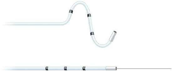
New technologies have emerged to assist in the placement of leads to targeted anatomic sites. Catheter‐delivered systems use a deflectable sheath that is braided to allow the simultaneous ability to torque and advance the catheter. A second, smaller lumen sheath can be used within the first sheath to enhance access to the coronary sinus and its venous tributaries, as well as serve as a conduit for contrast injections and lead delivery. A second technology developed to reach difficult anatomic targets is to use an over‐the‐wire lead delivery system (Fig. 1.16). With this system, the lead can be advanced to a stable position over a guidewire used initially to navigate tortuous regions of the coronary veins similar to techniques used extensively for coronary angiography. Using stiffer wires, like a stylet that does not exit the left ventricular lead, the leads can be pushed into position as well as have their relative geometries changed by the constraints of the stiff wire. Tip geometry changes allow the operator to change the early contour of the lead system dynamically to allow passage through tortuous veins. Flexibility in tool selection improves access to target sites across a broad range of anatomies and decreases injury to coronary venous structures. Through availability and/or combining of these multiple technologies, access to target sites has
Cathode Cathode
Fig. 1.16 Over‐the‐wire leads to facilitate placement in coronary vein branches. Top: lead with wire advanced beyond the distal end. The wire acts as a track over which the lead is advanced to provide stability. Bottom: lead with wire removed for final deployment.
improved greatly, particularly coronary vein subselection for left ventricular lead placement.
Modifications of tip geometries as well as a family of left ventricular leads to choose from have improved the stability of these passive leads. Furthermore, newer multipolar left ventricular leads provide a broad array of pacing configurations to facilitate favorable pacing thresholds and avoid phrenic nerve stimulation.45 Establishing a well‐positioned left ventricular lead position, and avoiding apical pacing, favorably influence long‐term outcomes with cardiac resynchronization.46
Another novel approach to using traditional leads for resynchronization involves utilizing the native His–Purkinje system to facilitate rapid activation of the ventricles synchronously. So called His bundle pacing theoretically allows for more physiologic ventricular activation; however, this approach may be limited by anatomic complexity, variability in degree of disease of the native conduction system, and lead stability in the region of interest. Unlike conventional active fixation leads, leads used for His bundle pacing rely on a fixed helix screw that consists of a smaller electrode to facilitate selective His bundle capture and minimize local nonselective myocardial activation. In addition, deployment typically relies on use of either a preformed, nonsteerable sheath with dual plane shaping or a steerable sheath, which optimizes the ability to direct the lead to the septal region. Currently, the lead used most often is a nonstylet‐driven exposed 4.1 French helical screw.
Epicardial leads
Though most commonly used leads consist of endocardially placed leads, epicardially placed leads are not uncommon, particularly in cases of leads placed in the operating room, and particularly in cases of difficult endocardial left ventricular lead placement or congenital heart disease in which endocardial pacing is not desired. These leads may involve a variety of fixation mechanisms distinct from that of endocardial leads, including epicardial stab‐in, myocardial screw‐in, or suture‐on leads. Though steroid‐eluting leads are
standard for endocardial placement, there is no clear effect on longevity for steroid‐ versus nonsteroid‐eluting epicardial leads. Similar to endocardial leads, both unipolar and bipolar configurations are possible, with the attendant benefits and risks seen with endocardial pacing also seen with epicardial leads.
Defibrillator leads – special considerations
As described previously, most defibrillator leads consist of similar design to that of endocardial pacing systems, albeit with addition of a coil to facilitate delivery of a high‐voltage shock to restore normal rhythm. Novel defibrillators consist of entirely subcutaneous leads with longer shock coils that do not rely on direct myocardial contact or fixation. These leads consist of a distal sensing electrode, an integrated anchoring hole, an 8 cm defibrillator coil, a proximal sensing electrode located just proximal to the coil, and a connector pin. Electrodes are polyurethane, and the suture sleeve is silicone. Subcutaneous lead form factors are currently evolving, with future designs being constructed to facilitate pacing as well as defibrillation and to optimize form factor for delivery into the substernal space.
Leadless pacemakers
Though most of the discussion has focused on lead design related to traditional leads, advances in battery technology, component design, communication technologies, and delivery tools has allowed for the development of entirely self‐contained leadless pacemakers. The principles outlined previously in terms of surface area of exposure to the myocardial interface and role of steroid‐eluting systems are applicable to leadless devices as well. Currently, leadless devices only exist for RV pacing and consist of fully self‐contained units. Either lithium carbon monofluoride or lithium–silver–vanadium oxide/carbon monofluoride battery systems are used. Both active fixation and passive fixation systems are used, depending on the manufacturer. Similarly, deployment and retrieval mechanisms may vary based on the manufacturer.
Pulse generators
All pulse generators include a power source, an output circuit, a sensing circuit, a timing circuit, and a header with a standardized connector (or connectors) to attach a lead (or leads) to the pulse generator.47 The exception to this is leadless pacemakers, which are entirely self‐contained, generally displacing about 1 cm3 in blood volume, and residing in the right ventricle (though multichamber leadless devices are in development). However, all devices are capable of storing some degree of diagnostic information that can be retrieved at a later time. Most pacemakers also incorporate some type of a rate‐adaptive sensor. The variety of novel sensors balanced against miniaturizing battery technology has led to a variable effect on the size and potential longevity of pulse generators.
Many power sources have been used for pulse generators over the years. Lithium iodine cells (consisting of varying types) have been the energy source for almost all contemporary pacemaker pulse generators. Newer pacemakers and implantable cardioverter‐defibrillators (ICDs) that can support higher current drains for capacitor charging and high‐rate antitachycardia pacing (ATP) use lithium–silver oxide–vanadium chemistries. Lithium is the anodal element and provides the supply of electrons; iodine is the cathodal element and accepts the electrons. The cathodal and anodal elements are separated by an electrolyte, which serves as a conductor of ionic movement but a barrier to the transfer of electrons. The circuit is completed by the external load (i.e., the leads and myocardium). The battery voltage of the cell depends on the chemical composition of the cell; at the beginning of life for the lithium iodine battery, the cell generates approximately 2.8 V, which decreases to 2.4 V when approximately 90% of the battery life has been used. The voltage then exponentially declines to 1.8 V as the battery reaches end‐of‐life. However, the voltage at which the cell reaches a specific degree of discharge is load dependent. The elective replacement voltages were chosen based on the shape of the discharge curves under expected operating conditions. When the battery is at end‐of‐service, most devices lose telemetry and programming capabilities, frequently reverting to a fixed high‐output pacing mode to maintain patient safety. This predictable depletion characteristic has made lithium‐based power cells common in current devices. Nickel–cadmium technology, as well as other metal‐based systems, are being considered again, however.
The battery voltage can be measured by communication with the pulse generator. In addition, most devices provide battery impedance (which increases with battery depletion) for additional information about battery life. The battery life can also be estimated by the magnet
rate of the device, which changes with a decline in battery voltage. Unfortunately, the magnet rates are not standardized, and rate change characteristics vary tremendously among manufacturers and even among devices produced by the same manufacturer. Therefore, it is important to know the magnet rate characteristics of a given device before using this feature to determine battery status.
The longevity of any battery is determined by several factors, including chemical composition of the battery, size of the battery, external load (pulse duration and amplitude, stimulation frequency, total pacing lead impedance, and amount of current required to operate device circuitry and store diagnostic information), amount of internal discharge, and voltage decay characteristics of the cell. The basic formula for longevity determination is
114 Battery capacityA h
Current drain Longevityyears A
However, this formula is subject to how the power cell’s ampere‐hours is specified by the manufacturer; thus, the longevity will vary somewhat by company. High‐performance leads, automatic capture algorithms, and programming options that minimize pacing may further enhance device longevity if not offset by energy consumption from running the software.48,49
The pacing pulse is generated first by charging an output capacitor with subsequent discharge of the capacitor to the pacing cathode and anode. Because the voltage of a lithium iodine cell is fixed, obtaining multiple selectable pulse amplitudes requires the use of a voltage amplifier between the battery and the output capacitor. Contemporary pulse generators are constant‐voltage (rather than constant‐current) devices, implying delivery of a constant‐voltage pulse throughout the pulse duration. In reality, some voltage drop occurs between the leading and the trailing edges of the impulse; the size of this decrease depends on the pacing impedance and pulse duration. The lower the impedance, the greater the current flow from the fixed quantity of charge on the capacitor and the greater the voltage drop throughout the pulse duration.50 The voltage drop is also dependent on the capacitance value of the capacitor and the pulse duration.
The output waveform is followed by a low‐amplitude wave of opposite polarity: the afterpotential. The afterpotential is determined by the polarization of the electrode at the electrode–tissue interface; formation is due to electrode characteristics, as well as to pulse amplitude and duration. The sensing circuit may sense afterpotentials of sufficient amplitude, especially if the sensitivity threshold is low. Newer pacemakers
use the output circuit to discharge the afterpotential quickly, thus lowering the incidence of afterpotential sensing. The afterpotential also helps to prevent electrode corrosion.
The intracardiac electrogram results from current conducted from the myocardium to the sensing circuit via the pacing leads, where it is then amplified and filtered. The input impedance must be significantly larger than the sensing impedance to minimize attenuation of the electrogram. A bandpass filter attenuates signals on either side of a center frequency, which varies between manufacturers (generally ranging from 20 to 40 Hz).51,52 After filtering, the electrogram signal is compared with a reference voltage: the sensitivity setting; signals with an amplitude of this reference voltage or higher are sensed as true intracardiac events and are forwarded to the timing circuitry, whereas signals with an amplitude below the reference amplitude are categorized as noise, extracardiac or other cardiac signal, such as T waves.
Sensing circuitry also incorporates noise reversion that causes the pacemaker to revert to a noise reversion mode (asynchronous pacing) whenever the rate of signal received by the sensing circuit exceeds the noise reversion rate. This feature is incorporated to prevent inhibition of pacing when the device is exposed to electromagnetic interference. Pulse generators also use Zener diodes designed to protect the circuitry from high external voltages, which may occur, for example, with defibrillation. When the input voltage presented to the pacemaker exceeds the Zener voltage, the excess voltage is shunted back through the leads to the myocardium.
The timing circuit of the pacemaker is an electronic clock that regulates the pacing cycle length, refractory periods, blanking periods, and AV intervals with extreme accuracy. The output from the clock (as well as signals from the sensing circuitry) is sent to a timing and logic control board that operates the internal clocks, which in turn regulate all the various timing cycles of the pulse generator. The timing and logic control circuitry also contains an absolute maximal upper rate cut‐off to prevent “runaway pacing” in the event of random component failure.53,54
Each new generation of pacemakers contains more microprocessor capability. The circuitry contains a combination of read‐only memory (ROM) and random‐access memory (RAM). ROM is used to operate the sensing and output functions of the device, and RAM is used in diagnostic functions. Larger RAM capability has allowed devices to store increased amounts of retrievable diagnostic information and patient‐specific longitudinal data, with the potential to allow downloading of new features externally into an implanted device.
External telemetry is supported in all implantable devices and in some pacemakers. The pulse generator can receive information from the programmer and send information back by radiofrequency signals. Each manufacturer’s programmer and pulse generator operate on an exclusive radiofrequency, preventing the use of one manufacturer’s programmer with a pacemaker from another manufacturer. Through telemetry, the programmer can retrieve both diagnostic information and real‐time information about battery status, lead impedance, current, pulse amplitude, and pulse duration. Real‐time electrograms and marker channels can also be obtained with most devices. The device can also be directed to operate within certain limits and to store specific types of diagnostic information via the programmer.
The most recent change in telemetry is that of “remote” capability. Information exchange has traditionally occurred by placing and leaving the programming “head” of the programmer over the pulse generator for the duration of the interrogation and programming changes. New telemetry designs allow the programming “head” or “wand” to be placed briefly over the pulse generator, or in the near vicinity of the device, to establish the identity of the specific model and pulse generator and then complete the bidirectional informational exchange at a distance; that is, the “wand” does not need to be kept in a position directly over the pulse generator. Finally, even the use of a wand for certain pulse generators is not required for remote programming. These technology advances have allowed remote monitoring of all implantable devices and, in some pacemakers, the use of home telemetry systems that upload patient‐ and device‐specific data to a central, secure database. With home monitoring, devices can be routinely monitored, patient alerts transmitted in real time, and patient cardiac status updates communicated on a programmable criteria basis. Remote monitoring of patients with ICDs improves survival and readily identifies risk markers of mortality.55
Pacemaker nomenclature
A lettered code to describe the basic function of pacing devices, initially developed by the American Heart Association and the American College of Cardiology, has since been modified and updated by the members of the North American Society of Pacing and Electrophysiology and the British Pacing and Electrophysiology Group (currently the Heart Rhythm Society).56 This code has five positions to describe basic pacemaker function, although it obviously cannot incorporate all of the various special features available on modern devices (Table 1.1).
Table 1.1 The North American Society of Pacing and Electrophysiology and the British Pacing and Electrophysiology Group (NBG) code.
I II III IV V
Chamber(s) paced Chamber(s) sensed Response to sensing Programmability, rate modulation Multisite pacing
O = None O =None O = None
A = Atrium A = Atrium
O = None O = None
T = Triggered P = Simple programmable A = Atrium
V = Ventricle V = Ventricle I = Inhibited M = Multiprogrammable V = Ventricle
D = Dual (A + V) D = Dual (A + V) D = Dual (T + I) C = Communicating D = Dual (A + V)
Source: Modified from Bernstein AD, Daubert JC, Fletcher RD, et al. The revised NASPE/BPEG generic code for antibradycardia, adaptive‐rate, and multisite pacing. North American Society of Pacing and Electrophysiology/British Pacing and Electrophysiology Group. Pacing Clin Electrophysiol 2002; 25:260–4, by permission of Futura Publishing Company.
The first position describes the chamber or chambers in which electrical stimulation occurs. A reflects pacing in the atrium, V implies pacing in the ventricle, D signifies pacing in both the atrium and the ventricle, and O is used when the device has ATP or cardioversion‐defibrillation capability but no bradycardia pacing capability.
The second position describes the chamber or chambers in which sensing occurs. The letter code is the same as that in the first position, except that an O in this position represents lack of sensing in any chamber; that is, fixed‐rate pacing. (Manufacturers may use an S in both the first and the second positions to indicate single‐chamber capability that can be used in either the atrium or the ventricle.)
The third position designates the mode of sensing; that is, how the device responds to a sensed event. I indicates that the device inhibits output when an intrinsic event is sensed and starts a new timing interval. T implies that an output pulse is triggered in response to a sensed event. D indicates that the device is capable of dual modes of response (applicable only in dual‐chamber systems).
The fourth position reflects both programmability and rate modulation. O indicates that none of the pacemaker settings can be changed by noninvasive programming, P suggests “simple” programmability (i.e., one or two variables can be modified), M indicates multiprogrammability (three or more variables can be modified), and C indicates that the device has telemetry capability and can communicate noninvasively with the programmer (which also implies multiprogrammability). Finally, an R in the fourth position designates rate‐responsive capability. This means that the pacemaker has some type of sensor to modulate the heart rate independent of the intrinsic heart rate. All modern devices are multiprogrammable and have telemetry capability; therefore, the R to designate rate‐responsive capability is the most commonly used currently.
The fifth position was originally used to identify antitachycardia treatment functions. However, this has been changed, and antitachycardia options are no longer included in the nomenclature. The fifth position now indicates whether multisite pacing is not present (O), or present in the atrium (A), ventricle (V), or both (D). Multisite pacing is defined for this purpose as stimulation sites in both atria, both ventricles, more than one stimulation site in any single chamber, or any combination of these.
All pacemaker functions (whether single, dual, or multi‐chamber) are based on timing cycles. Even the function of the most complex devices can be readily understood by applying the principles of pacemaker timing intervals. This understanding is critical for accurate interpretation of pacemaker ECGs, especially during troubleshooting. Pacemaker timing cycles are described in detail in Chapter 7 (Timing Cycles).
Essentials of defibrillation
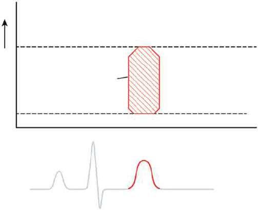
In 1899, Prevost and Battelli57 noted that the “fibrillatory tremulations produced in the dog” could be arrested with the reestablishment of the normal heartbeat if one submitted the animal “to passages of current of high voltage.” With the development of internal defibrillators in the late 1970s came a greater need to quantify defibrillation effectiveness, to understand the factors governing waveform and lead design, and to determine the effect of pharmacologic agents on defibrillation.
A few hypotheses have been proposed to explain how an electric shock terminates fibrillation: critical mass, upper limit of vulnerability (ULV), progressive depolarization, and virtual electrode depolarization. These hypotheses, which are not entirely mutually exclusive, are summarized in the following subsections.
In its resting state, the myocardium is excitable, and a pacing stimulus, or current injected by the depolarization of a neighboring myocyte, can bring the membrane
potential to a threshold value, above which a new action potential ensues. The ability of the action potential of a myocyte to depolarize adjacent myocardium results in propagation of electrical activity through cardiac tissue. Importantly, immediately after depolarization, the myocardium is refractory and cannot be stimulated to produce another action potential until it has recovered excitability. The interval immediately after an action potential, during which another action potential cannot be elicited by a pacing stimulus, is referred to as the “refractory period.”
VF results when an electrical wavebreak induces reentry and results in a cascade of new wavebreaks. In patients with a structurally abnormal or diseased heart, the underlying tissue heterogeneity results in a predisposition to wavebreak, then reentry, and finally fibrillation.58 These wandering wavelets are self‐sustaining once initiated. In the 1940s, Gurvich and Yuniev59 predicted that electric shocks led to premature tissue stimulation in advance of propagating wave fronts, preventing continued progression of the wave front. This concept of defibrillation as a large‐scale stimulation remains a central tenet of many of the currently held theories of defibrillation.
Critical mass
The critical mass theory proposed that shocks need only eliminate fibrillatory wavelets in a critical amount of myocardium to extinguish the arrhythmia. Experiments in canine models found that injection of potassium chloride (which depolarizes myocardium, rendering it unavailable for fibrillation) into the right coronary artery or the left circumflex artery failed to terminate VF as often as injection into both the left circumflex and the left anterior descending arteries together. Similarly, electrical shocks of equal magnitude terminated fibrillation most frequently when the electrodes were positioned at the RV apex and the posterior left ventricle, as opposed to two RV electrodes. Thus, it was concluded that if a “critical mass” of myocardium was rendered unavailable for VF, either by potassium injection or by defibrillatory shock, then the remaining excitable tissue was insufficient to support the wandering wavelets, and the arrhythmia terminated.60 However, it was not critical to depolarize every ventricular cell to terminate fibrillation. This is an important consideration when implanting a defibrillator, as the overall quantity of heart muscle contained within the region through which a defibrillatory shock travels is critical to the success of a shock to successfully restore normal rhythm. Thus, placement of the lead or epicardial patches relative to the generator in such a position as to encompass the largest volume of myocardium is one means by which to optimize defibrillatory success.
Upper limit of vulnerability
Studies mapping electrical activation after failed shocks led to several observations not accounted for by the critical mass hypothesis, giving rise to the ULV theory. First, an isoelectric interval (an electrical pause) was seen after failed shocks before resumption of fibrillation. The relatively long pause suggested that VF was terminated by the shock and then secondarily regenerated by it.61 The concept that failed shocks are unsuccessful because they reinitiate fibrillation rather than because they fail to halt continuing wavelets was further buttressed by a second observation: that post‐shock conduction patterns were not the continuation of preshock wave fronts.62 If a failed shock resulted from the inability to halt continuing fibrillation, the assumption was that the post‐shock wave fronts should be a continuation of the propagating wave fronts present before shock delivery and that new wave fronts at sites remote from the preshock wave fronts would not be expected. Furthermore, VF was frequently reinitiated in the regions of lowest shock intensity, suggesting that these low‐intensity regions were responsible for reinitiating fibrillation. Shocks that fall into the vulnerable period (which overlaps the T wave during normal rhythm) with an energy above the lower limit of vulnerability and below the ULV induce VF. Shocks with energies above the ULV never induce VF, and thus defibrillate (Fig. 1.17).
Elegant mapping studies demonstrated that shocks with potential gradients less than a minimum critical value (termed the ULV; 6 V/cm for monophasic shocks, 4 V/cm for biphasic shocks) could induce fibrillation when applied to myocardium during its vulnerable period. Low‐energy shocks did so by creating regions of functional block in vulnerable myocardium at “critical points” that initiated reentry and subsequent fibrillation.63 Importantly, this theory permits linking of defibrillation and fibrillation. In sinus rhythm, low‐energy shocks delivered during the vulnerable period (the T wave) induce VF; higher energy shocks – with energy above the ULV – do not (Fig. 1.18). Because at any given time during fibrillation a number of myocardial regions are repolarizing and thus vulnerable, a shock with a potential gradient below the ULV may create a critical point and reinitiate fibrillation. Conversely, a shock with a gradient above the ULV across the entire myocardium does not reinduce VF and should, therefore, succeed. During defibrillator testing, shocks are intentionally delivered in the vulnerable zone to induce fibrillation (Fig. 1.18); the zone of vulnerability has been defined in humans.64 The fact that the vulnerable zone exists and that the ULV has been correlated with the DFT supports the ULV hypothesis as a mechanism of defibrillation, and permits its use at implant testing.65
Vulnerable window Shoc k ener
Defibrillation energy range
VF induction energy range
Upper limit of vulnerability
Lower limit of vulnerability
Time (Fibrillation threshold)
Fig. 1.17 Window of vulnerability during sinus rhythm. During sinus rhythm, the ventricles are vulnerable to ventricular fibrillation (VF) when a shock is delivered on the T wave, in the vulnerable window. To induce fibrillation, the shock energy must be greater than the lower limit of vulnerability (the fibrillation threshold) and below the upper limit of vulnerability (ULV). Shocks with energy above the upper limit of vulnerability do not induce fibrillation. Because during VF there is dyssynchrony of activation, at any given instant a number of regions are repolarizing (equivalent to the T wave in sinus rhythm), so that a shock with a gradient that is less than the ULV can reinduce fibrillation in these regions. In contrast, shocks with energy above the ULV throughout the myocardium cannot reinitiate VF and are successful. The ULV is correlated with the defibrillation threshold. Further details appear in the text.
Progressive depolarization
A third theory of defibrillation, the progressive depolarization theory (also referred to as the “refractory period extension theory”), incorporates some elements of both critical mass and ULV theories. Using voltage‐sensitive optical dyes, Dillon and Kwaku66 have demonstrated that shocks of sufficient strength were able to elicit responses, even from supposedly refractory myocardium. Thus, as seen in Fig. 1.19, the duration of an action potential can be prolonged (and the refractory period extended) despite refractory myocardium when a sufficiently strong shock is applied.67 This phenomenon may result from sodium channel reactivation by the shock. The degree of additional depolarization time is a function of both shock intensity and shock timing.68 Because the shock stimulates new action potentials in myocardium that is late in repolarization and produces additional depolarization time when the myocardium is already depolarized, myocardial resynchronization occurs. This is manifested by myocardial repolarization at a constant time after the shock (second dashed line in Fig. 1.19, labeled “constant repolarization time”). Thus, the shock that defibrillates extends overall ventricular refractoriness, limiting the excitable tissue available for fibrillation. Thus, it extinguishes continuing wavelets and resynchronizes repolarization, so that distant regions of myocardium become excitable simultane-
ously, preventing dispersion of refractoriness and renewed reentry. Experimental evidence has demonstrated that shocks with a potential gradient above the ULV result in time‐dependent extension of the refractory period. In contrast, lower energy shocks may result in a graded response that could create transient block and a critical point, thereby reinducing fibrillation.68 Note, whereas progressive depolarization and virtual electrode depolarization (discussed next) address cellular mechanisms of shock induced reentry, the ULV and critical mass hypotheses do not postulate a specific mechanism, but only that shock‐induced reentry is an important mechanism of failed subthreshold shocks.
Virtual electrode depolarization
More recently, optical signal measurements of transmembrane potentials have demonstrated the concept of the “virtual electrode.”69 The virtual electrode effect refers to stimulation of tissue far from the implanted electrode. This effect makes the defibrillation electrode effectively much larger than the physical electrode. In the virtual electrode, the anode cells are brought close to their resting potential, increasing their responsiveness to stimulation. More importantly, the region of depolarization or hyperpolarization near the physical electrode is surrounded by regions with opposite polarity. Anodal shocking produces a wave front of