
Karl Fink
Visit to download the full and correct content document: https://ebookmass.com/product/plastics-process-analysis-instrumentation-and-control -johannes-karl-fink/
More products digital (pdf, epub, mobi) instant download maybe you interests ...

Fundamentals of Industrial Instrumentation and Process Control, Second Edition William C Dunn
https://ebookmass.com/product/fundamentals-of-industrialinstrumentation-and-process-control-second-edition-william-cdunn/
Process Control Instrumentation Technology 8th Edition
Curtis D. Johnson
https://ebookmass.com/product/process-control-instrumentationtechnology-8th-edition-curtis-d-johnson/
Instrumentation And Control Systems Reddy
https://ebookmass.com/product/instrumentation-and-controlsystems-reddy/
Instrumentation and Control Systems William Bolton
https://ebookmass.com/product/instrumentation-and-controlsystems-william-bolton/
Instrumentation, Measurement and Analysis 4th Edition
Chaudhary Nakra
https://ebookmass.com/product/instrumentation-measurement-andanalysis-4th-edition-chaudhary-nakra/
Industrial Automated Systems: Instrumentation and Motion Control 1st Edition – Ebook PDF Version
https://ebookmass.com/product/industrial-automated-systemsinstrumentation-and-motion-control-1st-edition-ebook-pdf-version/

Process
Control 4th Edition Sohrab Rohani (Ed.)
https://ebookmass.com/product/process-control-4th-edition-sohrabrohani-ed/
Advanced Chemical Process Control 1st Edition Morten Hovd
https://ebookmass.com/product/advanced-chemical-processcontrol-1st-edition-morten-hovd/
Process
Control: Modeling,
Design,
and
Simulation
2nd Edition B. Wayne Bequette
https://ebookmass.com/product/process-control-modeling-designand-simulation-2nd-edition-b-wayne-bequette/

100CummingsCenter,Suite541J
Beverly,MA01915-6106
PublishersatScrivener
MartinScrivener(martin@scrivenerpublishing.com)
PhillipCarmical(pcarmical@scrivenerpublishing.com)
JohannesKarlFink
MontanuniversitätLeoben,Austria
Scrivener
Copyright © 2021byScrivenerPublishingLLC.Allrightsreserved.
Co-publishedbyJohnWiley&Sons,Inc.,Hoboken,NewJersey,and ScrivenerPublishingLLC,Salem,Massachusetts. PublishedsimultaneouslyinCanada
Nopartofthispublicationmaybereproduced,storedinaretrievalsystem,ortransmittedinanyformorbyanymeans,electronic,mechanical,photocopying,recording,scanning,orotherwise,exceptaspermittedunderSection107or108ofthe1976UnitedStatesCopyrightAct, withouteitherthepriorwrittenpermissionofthePublisher,orauthorizationthroughpaymentoftheappropriateper-copyfeetotheCopyright ClearanceCenter,Inc.,222RosewoodDrive,Danvers,MA01923,(978) 750-8400,fax(978)750-4470,oronthewebatwww.copyright.com. RequeststothePublisherforpermissionshouldbeaddressedtothe PermissionsDepartment,JohnWiley&Sons,Inc.,111RiverStreet, Hoboken,NJ07030,(201)748-6011,fax(201)748-6008,oronlineat http://www.wiley.com/go/permission.
LimitofLiability/DisclaimerofWarranty:Whilethepublisherandauthor haveusedtheirbesteffortsinpreparingthisbook,theymakenorepresentationsorwarrantieswithrespecttotheaccuracyorcompletenessof thecontentsofthisbookandspecificallydisclaimanyimpliedwarranties ofmerchantabilityorfitnessforaparticularpurpose.Nowarrantymay becreatedorextendedbysalesrepresentativesorwrittensalesmaterials.Theadviceandstrategiescontainedhereinmaynotbesuitablefor yoursituation.Youshouldconsultwithaprofessionalwhereappropriate.Neitherthepublishernorauthorshallbeliableforany lossofprofit oranyothercommercialdamages,includingbutnotlimitedtospecial, incidental,consequential,orotherdamages.
Forgeneralinformationonourotherproductsandservicesorfortechnical support,pleasecontactourCustomerCareDepartmentwithintheUnited Statesat(800)762-2974,outsidetheUnitedStatesat(317) 572-3993orfax (317)572-4002.
Wileyalsopublishesitsbooksinavarietyofelectronicformats.Some contentthatappearsinprintmaynotbeavailableinelectronicformats.FormoreinformationaboutWileyproducts,visitourwebsite atwww.wiley.com.
FormoreinformationaboutScrivenerproductspleasevisit www.scrivenerpublishing.com.
CoverdesignbyRussellRichardson
Preface
Thisbookfocusesonplasticsprocessanalysis,instrumentation,and control.Here,thesubjectofprocessanalysis,instrumentationand controlformodernmanufacturingintheplasticsindustryaredetailed.
Processanalysisisthestartingpointsinceplasticsprocessingis differentfromprocessingofmetals,ceramics,andothermaterials. Plasticsmaterialsshowuniquebehaviorintermsofheattransfer, fluidflow,viscoelasticbehavior,andadependenceoftheprevious time,temperatureandshearhistorywhichdetermineshowthematerialrespondsduringprocessinganditsenduse.Manyofthe manufacturingprocessesarecontinuousorcyclicalinnature.The systemsareflowsystemsinwhichtheprocessvariables,suchas time,temperature,position,meltandhydraulicpressure, mustbe controlledtoachieveasatisfactoryproductwhichistypicallyspecifiedbycriticaldimensionsandphysicalpropertieswhichvarywith theprocessingconditions.Instrumentationhastobeselectedsothat itsurvivestheharshmanufacturingenvironmentofhighpressures, temperaturesandshearrates,andyetithastohaveafastresponse tomeasuretheprocessdynamics.Manytimesthemeasurements havetobeinanon-contactmodesoasnottodisturbthemeltor thefinishedproduct.Plasticsresinsarereactivesystems. Theresins willdegradeiftheprocessconditionsarenotcontrolled.Analysis oftheprocessallowsonetostrategizehowtominimizedegradation andoptimizeend-useproperties.
Themaingoalofthebookistocoverthefieldofautomaticprocess controlandinstrumentationforplasticsprocessingandalsothenew topicsofstatisticalprocesscontrolandprocessmonitoring,which arerequiredtodocumentgoodmanufacturingpractices.
Thetextfocusesontheliteratureofthepastdecade.Beyond education,thisbookwillservetheneedsofindustryengineersand
specialistswhohaveonlyapassingknowledgeoftheplasticsand compositesindustriesbutneedtoknowmore.
HowtoUseThisBook
Utmostcarehasbeentakentopresentreliabledata.Becauseofthe vastvarietyofmaterialpresentedhere,however,thetextcannotbe completeinallaspects,anditisrecommendedthatthereaderstudy theoriginalliteratureformorecompleteinformation.
ThereadershouldbeawarethatmostlyUSpatentshavebeen citedwhereavailable,butnotthecorrespondingequivalentpatents inothercountries.Forthisreason,theauthorcannotassumeresponsibilityforthecompleteness,validityorconsequencesofthe useofthematerialpresentedherein.Everyattempthasbeen made toidentifytrademarks;however,thereweresomethattheauthor wasunabletolocate.
Index
Therearethreeindices:anindexofacronyms,anindexofchemicals,andageneralindex.Intheindexofchemicals,compounds thatoccurextensively,e.g.,“acetone,”arenotincludedatevery occurrence,butratherwhentheyappearinanimportantcontext.
Acknowledgements
Iamindebtedtoouruniversitylibrarians,Dr.ChristianHasenhüttl, MargitKeshmiri,FriedrichScheer,ChristianSlamenik,Renate Tschabuschnig,andElisabethGroßforsupportinliteratureacquisition.Ialsowanttoexpressmygratitudetoallthescientistswho havecarefullypublishedtheirresultsconcerningthetopicsdealt withherein.Thisbookcouldnothavebeenotherwisecompiled.
Last,butnotleast,Iwanttothankthepublisher,MartinScrivener, forhisabidinginterestandhelpinthepreparationofthetext.Inaddition,mythanksgotoJeanMarkovic,whomadethefinalcopyedit withutmostcare.
JohannesFink
Leoben,10thNovember2020
1.1SubjectsoftheBook....................1 1.2SpecialIssues.......................2 1.3InjectionMolding.....................3
1.3.1CostEstimationinInjectionMolding.....3
1.3.2CostPredictionModels.............4
1.4MiniatureMoldingProcesses..............6
1.5ComputerDeterminationofWeldLinesinInjection Molding..........................6
1.6ExtrusionBlowMolding.................8
1.6.1RapidThermalCyclingMolding........8
1.6.2RapidHeatCycleMolding...........8
1.6.3InjectionMolding:Heating...........16
1.7MicrocellularInjectionMolding.............22 1.8MoldCooling.......................23
1.9MicrocellularFoamProcessingSystem.........27
1.9.1Gas-AssistedInjectionMolding.........27
1.9.2Water-AssistedInjectionMolding.......32
1.10MoldingMachineforGranules.............32
1.15.1MarinePollution.................43
1.15.3Recycling.....................45
References............................57
2ProcessAnalysis 65
2.1ConceptsandStrategies.................66
2.1.1Chemometrics...................67
2.1.2SafetyRisks....................68
2.1.3FeedbackProcedures...............68
2.2LinearSystems......................68
2.2.1SimpleFirst-OrderSystems...........68
2.2.2FractionalOrderSystems............69
2.2.3NonlinearSystemsandLinearization.....69
2.2.4CharacteristicsofSystems............75
2.2.5ControllersandControllerSettings.......84
2.3Twin-ScrewExtrusion..................91 References............................92
3ExamplesofProcessAnalysis99
3.1GreenhouseGasBalance.................99
3.1.1Poly(ethylenefurandicarboxylate).......99
3.1.2PolyesterBinder.................100
3.2InjectionMoldingTechnology..............101
3.2.1ModuleforCADModelingofthePart.....103
3.2.2ModuleforNumericalSimulationofInjection MoldingProcess.................104
3.2.3ModuleforCalculationofParameters ofInjectionMoldingandMoldDesign CalculationandSelection............105
3.2.4ModuleforMoldModeling...........106
3.2.5ExamplesofTesting...............107
3.2.6MoldingAirCooling...............108
3.2.7CavityPressure..................109
3.2.8PlasticsExtruderDynamics...........110
3.2.9HistoryofMathematicalModeling.......110
3.2.10CurrentPhysicalComponentsConcept....112
3.2.11ProcessStages...................112
3.2.12DataEnvelopmentAnalysis...........116
3.2.13TaguchiMethod..................118
3.2.14TaitModel.....................119
3.2.15Phan-Thien-TannerModel............121
3.2.16ProductQualityPrognosis............121
3.2.17ProductionPredictiveControl.........122
3.2.18ParameterOptimizationforEnergySaving..123
3.2.19MultilayerControlSystem............124
3.2.20SmoothedParticleHydrodynamicsMethod.125
3.2.21Temperature-DependentAdaptiveControl..126
3.2.22Micro-InjectionMolding.............128
3.2.23ImmisciblePolymerBlends...........131
3.2.24ResinInjectionMolding.............133
3.2.25FoamInjectionMolding.............137
3.2.26Self-OptimizingInjectionMoldingProcess..138
3.2.27MachineSetup..................140
3.3ShrinkageinInjectionMolding.............146
3.3.1FactorsthatAffecttheShrinkage........146
3.3.2EffectofaCoolingSystem............147
3.3.3InfluenceofMoldingConditionsonthe ShrinkageandRoundness............148
3.3.4ShearViscosity..................148
3.3.5 In-Situ ShrinkageSensor.............149
3.3.6SemicrystallinePolymer.............151
3.3.7ThermoplasticElastomers............151
3.3.8ReprocessingofABS...............153
3.3.9SequentialSimplexAlgorithmwithAutomotive VentiductGrid..................155
3.3.10Taguchi,ANOVA,CAE,andNeuralNetwork Methods......................156
3.4RecyclingbyExtrusion..................166
3.4.1MultipleIn-LineExtruders...........166
3.4.2MixedPost-ConsumerPlasticWaste......167
3.4.3Poly(methylmethacrylate)...........168
3.4.4Poly(ethyleneterephthalate)..........169
3.4.5Poly(lacticacid)..................169
3.4.6ExpandedPoly(styrene).............169
3.5BatchWashingofRecycledFilms............171
3.5.1RecyclingofPoly(styrene)Waste........171
3.5.2TextileFinishing.................172
3.5.3RemovingScrapfromContainers.......173
3.5.4AdsorptionIsothermsandDesorptionRates.175
3.6Self-PurgingMicrowavePyrolysis...........176
3.7PurgingandPlasticizationinInjectionMolding....177
3.7.1AutomaticPurging................177
3.8HotRunnerSystems...................179
3.8.1HotRunnerMoldwithRunnerPipe......180
3.8.2HotRunnerSysteminPlasticsMoldingTools183
3.8.3ManufacturingandAssemblingofHot RunnerSystems..................184
3.9BlownFilmExtrusionandThicknessControl.....185
3.10ResidenceTimeDistributionforBiomassPyrolysis..186
3.11ReactiveExtrusion....................187 References............................187
4ProcessInstrumentation201
4.1In-MoldMeasurement..................201 4.2Temperature........................202
4.2.1SoftActuator...................202
4.2.2Thermocouples..................202
4.2.3ResistanceTemperatureDetectors.......206
4.2.4ThinFilmMiniatureTemperatureSensors..214
4.2.5NeuralNetworks.................214
4.3PositionTransducers...................215
4.3.1RotaryPositionTransducer...........215
4.3.2LinearVariableDifferentialTransformers...216
4.3.3OpticalEncoders.................218
4.3.4ThicknessGauges.................218
4.4CompositionofMatter..................222
4.4.1IRInterferometerforMultilayerFilm.....222
4.4.2X-RayDiffraction.................225
4.4.3IonMobility-MassSpectrometry........226
4.4.4TestforIceAdhesionStrength.........226
4.4.5PiezoelectricCoaxialFilamentSensors.....228
4.4.6InstrumentationforImpactTesting.......228
4.4.7TreatmentofTitaniumSurfaces.........229
4.4.8SpatialDifferentiationofSub-Micrometer Domains......................230
4.5MedicalIssues.......................231
4.5.1EndoscopicPlasticSurgicalProcedures....231
4.5.2MedicalCatheters................231
4.5.3MultichannelPlasticJoint............237
4.5.4TransluminalEndoscopicSurgery.......238
4.5.5Wire-ActuatedUniversal-JointWrists.....238
4.5.6MusculoskeletalDisorders...........239 References............................240
5ActuatorsandFinalControlElements245
5.1ServoValves........................245
5.1.1NozzleAssemblyforaServoValve......245
5.2ServoMotors........................248
5.2.1HydraulicSystem.................248
5.2.2FunctionallyGradedMaterials.........248
5.3SolenoidValves......................251
5.3.1DesignVerificationMethodology........251
5.3.2SmallSolenoidValve...............252
5.3.3High-SpeedSolenoidValve...........252
5.3.4NumericalSimulation..............252
5.4Heaters...........................253
5.4.1ConductionHeaters...............253
5.4.2RadiantHeaters..................255
5.4.3HeaterControls..................255
5.5DriveMotorsandMotorSpeedControlforExtrusion256
5.5.1Single-DriveMotor................256
5.5.2LinearInductionMotor.............256
5.5.3MotorPowerConsumptioninSingle-Screw Extrusion.....................257
5.5.4DualMotorMulti-Head3DPrinter.......258 References............................258
6AnalysisofMeltProcessingSystems261
6.1ProcessParameterDeterminationofPlasticInjection Molding..........................261
6.1.1Case-BasedReasoningMethod.........261
6.1.2Knowledge-BasedReasoningMethod.....264
6.1.3Rule-BasedReasoningMethod.........265
6.1.4FuzzyReasoningMethod............266
6.2ProcessParameterDeterminationofPlasticInjection MoldingofLCDs.....................267
6.3ProcessingHistory....................267
6.3.1FlowDefects....................267
6.3.2Biocomposites...................269
6.3.33DPrinting....................271
6.3.4SemiconductingPolymerBlends........272
6.3.5VanGurp-PalmenPlot..............272
6.3.6NanocrystalComposites.............273
6.3.7Melt-Mastication.................274
6.3.8CrystalNucleationinNanocomposites....275
6.4ShearHistory.......................276
6.5ExtrusionProductControl................278
6.5.1BranchedStructures...............278
6.5.2BigAreaAdditiveManufacturing.......279
6.5.3Single-ScrewExtrusionControl.........280
6.5.4BlownFilm....................284
6.5.5ChillRollCastFilm................285
6.5.6Sheet........................292
6.5.7Profiles.......................294
6.5.8PipeandTubing.................297
6.5.9AutomaticScreenChangers...........303
6.6ExtrusionBlowMoldingParisonControl.......306
6.7InjectionMolding.....................310
6.7.1RamVelocityControl...............310
6.7.2PressureControl.................313
6.7.3Gas-AssistedControl...............319
6.7.4SystemDiagnostics................322
6.7.5StatisticalProcessandQualityControl.....328
6.8Thermoforming......................329
6.8.1TwinSheetThermoforming...........329
6.8.2RotaryThermoforming.............330
6.8.3ProcessModelforThermoforming.......331
6.9Rotomolding........................332
6.9.1PolymerCompositionsforRotomolding...334
6.10Compounders.......................348
6.10.1HistoryofCompounding............348
6.10.2TypesofCompounders.............348
6.10.3SpecialApplications...............350 References............................352
7.2.1DryingTemperatures...............364
7.2.2MoistureContent.................366
7.2.3ResinDryers....................366 7.2.4PelletDryers....................369
1 GeneralAspects
1.1SubjectsoftheBook
Thisbookintroducesthesubjectofprocessanalysis,instrumentationandcontrolformodernmanufacturingintheplasticsindustry. Processanalysisisthestartingpointsinceplasticsprocessingis differentfromprocessingofmetals,ceramics,andothermaterials. Plasticsmaterialsshowanuniquebehaviorintermsofheattransfer, fluidflow,viscoelasticbehavior,andadependenceontheprevious time,temperatureandshearhistorywhichdetermineshowthematerialrespondsduringprocessinganditsenduse.
Manyofthemanufacturingprocessesarecontinuousorcyclicalin nature.Thesystemsareflowsystemsinwhichtheprocessvariables, suchastime,temperature,position,meltandhydraulicpressure, mustbecontrolledtoachieveasatisfactoryproduct,which istypicallyspecifiedbycriticaldimensionsandphysicalpropertieswhich varywiththeprocessingconditions.Instrumentationhastobeselectedsothatitsurvivestheharshmanufacturingenvironmentof highpressures,temperaturesandshearratesandyetithastohave afastresponsetomeasuretheprocessdynamics.Manytimesthe measurementshavetobeinanon-contactmodesoasnottodisturb themeltorthefinishedproduct.Plasticsresinsarereactivesystems. Theresinswilldegradeiftheprocessconditionsarenotcontrolled. Analysisoftheprocessallowsonetostrategizehowtominimize degradationandoptimizeenduseproperties.
Linearsystemsinwhichthereexistsaone-to-onerelationship betweentheinputvariableandtheoutputresponsearetheeasiest
2Plastics Process Analysis,Instrumentation, and Control
toanalyzeandcontrol.Plasticsontheotherhandshowanonlinear dependenceonpart/productcoolingwhichvarieswiththesquare ofthepartthickness,laminarflowwhichvarieswiththecubeof thewallthicknessandmechanicalstrength/stiffnesswhichvaries withthecubeofwallthickness.Also,wallthicknessinfluencesthe crystallization,shrinkage,morphologyandcriticaldimensionsof theproduct.
Inordertomakecorrectionstotheprocess,actuators,also known asfinalcontrolelements,mustintroduceenergytothesystem.This hardwareisintheformofservovalves,solenoidvalves,servo motors,heaters,andblowers.Thesizing,responsetime,ruggedness andlinearitymustbeconsidered.Alltheabovehardwarehastobe assembledintoasystemandprogrammedwithasuitablealgorithm tocarryoutautomaticcontrol.Thecontrolconfigurationand the algorithmaredictatedbythesystemitself.Commoncontrol modes arefeedbacksetpointcontrolwhichiscommoninextrusion, servo controlwhichiscommonininjectionmoldingandblowmolding cyclicalprocesses,andcombinationsandvariationsthereof.
1.2SpecialIssues
Asimplified,practical,andinnovativeapproachtounderstandthe designandmanufactureofplasticproductsintheWorldofPlastics hasbeenpresented(1).
Theinformationdefinesandfocusesonpast,current,andfuture technicaltrends.Thishandbookreviewsmorethan20,000different subjects.
Variousplasticmaterialsandtheirbehaviorpatternswere reviewed.Examplesareprovidedofdifferentplasticproductsand criticalfactorsrelatingtothemthatrangefrommeetingperformance requirementsindifferentenvironmentstoreducingcostsandtargetingforzerodefects(1).
1.3InjectionMolding
1.3.1CostEstimationinInjectionMolding
Costandperformanceestimationarefrequentlyusedattheearly stagesofproductdevelopmenttodeterminethefeasibility anddrive criticaldesigndecisions.Earlycostestimationhasbeenhampered bytheunavailabilityanduncertaintyofinformation.
Here,costestimateswerederivedfromacomplexitymetricas definedbythenumberofdimensionsthatuniquelydefinethepart geometry(2).
Thecostdriversofmanufacturinganinjectionmoldedplastic part Cpart areexpressedinEq.1.1.
Thematerialcostcontribution, Cmat,isverysignificant,typically 50%to80%ofthetotalpartcost.Toolingandprocessingcostsare alsosignificantcostdrivers.Theprocessingcost, Cproc,isdependent onthehourlyratechargedfortheusageoftheinjectionmolding machineaswellastheprocessingyield, yproc,whichistheratioof goodpartstothetotalnumberofpartsproduced.Thetoolingcost, Ctool,isamortizedovertheestimatedproductionquantity N forthe lifeofthetool.
Eq.1.2isanexpressionfortheassembledproductcost.
The m partsthatconstitutetheproductincludebothinjection moldedandstandardpurchasedparts.Thecostoftheassembly is theproductoftheassemblyshophourlyrate, Rassy,andthetotaltime requiredtoassemblethe m partsconstitutingtheproduct.Thus,the assemblycostdecreasesaspart-count m decreases.Theoverhead costperproduct COH includesboththeshopandtheadministrative overheads.
Dimensionalityandothercriticaldesignvariablescanbeautomaticallyassessedwithinmoderncomputer-aideddesignsystems throughouttheproductdevelopmentprocesstoprovidecontinual feedbackregardingtooling,process,andmaterialcosts(2).
4Plastics Process Analysis,Instrumentation, and Control
Thecomplexity-basedmodelsweredevelopedandtestedwith empiricaldataforthirtyinjectionmoldedpartsfromdifferentsuppliersandwasfoundtohaveahighlysignificantcorrelation with moldcostsandtoolingleadtimes.Modelsforestimatingmaterial andprocessingcostsandyieldattheearlystagesofdesignarealso developed.Thedevelopedmethodsenablereal-timeevaluationof theeffectsofaproductdesignonitstoolingcost,toolingleadtime, processingcosts,andyieldattheearlystagesofdesign(2).
1.3.2CostPredictionModels
Withtherecentevolutionofadditivemanufacturing,accuratecost predictionmodelsareofincreasingimportancetoassistdecisionmakingduringproductdevelopmenttasks(3).Estimatingthecost isachallengingtaskinthatitrequiresavastamountofmanufacturingknowledgeinwhichmanyaspects,fromdesigntoproduction, needtobesynchronized.Asaresult,variousadditivemanufacturingcostmodelshavebeendeveloped.
Thestateoftheartinproductcostestimationcoveringvarious techniquesanddevelopedmethodologieshasbeenreviewed(4). Theoverallworkcanbecategorizedintoqualitativeandquantitativetechniques.Thequalitativetechniquesarefurthersubdivided intointuitiveandanalogicaltechniques,andthequantitativeones intoparametricandanalyticaltechniques.Also,theimportanceof costestimationintheearlyphasesofthedesigncycleisdiscussed inthereview(4).Thecostclassificationtechniquesaresummarized inTable1.1.
Also,morerecently,anoverviewwaspresentedofthecosting modelsbeingdevelopedandutilizedassociatedwiththeadditive manufacturingproductdevelopmentphases(3).Here,itwas observedthatthecontextsandviewsdescribedduringthedevelopmentofthemodelswereoftentargetedatspecificapplicationsas wellastechnologiesandwereclassifiedinmanyways.Accordingly, differentaspectsofthecostestimationclassificationtechniquewere detailedanddefinitionsofsomeofthekeyterminologieswerereported.
Since2006,atotaloftenreviewworksrelatedtocostinginadditivemanufacturingwerereportedinwhicheachdifferedsignif-
Table1.1 Costclassificationtechniques(3).
ClassificationtechniquesDefinition
Method-basedQualitative: Intuitive Basedontheexperienceofthe estimator
Qualitative: Analogy Basedonhistoricaldata.Acomparisonisoftenmadebetween oldpartsandnewpartsduring estimation
Quantitative: Parametric Basedonstatisticalregression expressionwherevariablesare referredtoascostdrivers
Quantitative: Analytical Basedonproductdecompositionintounits,operations,or activitiesthatrelatetohowto manufacturetheproduct
Task-basedDesign-orientedBasedondesign-relatedactivities Process-orientedBasedontheprocessofcommissioningtheproductdevelopmentactivitiescoveringproduction-relatedandpost-processing costs
Level-basedProcess-levelBasedontheproductioncost, whichinvolvesentireproduct developmentphases(preprocessing,productionand post-processing)
System-levelBasedonproductlifecyclethat coverssupplychain,operation managementandsystem-level services
6Plastics Process Analysis,Instrumentation, and Control icantlyintermsoftheirscope.TheseworksarecollectedinTable 1.2.
1.4MiniatureMoldingProcesses
Inachapterofamonograph,particularprocessingstrategiesand techniquesforinjectionmoldingofprecisionparts,thinwallparts, microstructuredparts,andmicropartshavebeendescribed (5).
Theimportanceofincorporatingsizeeffectsintothefillingsimulationofmicrocavitieshasbeendemonstrated.Thestandard injectionmoldingsimulationandspecialsimulationneedsforminiature moldingprocesseshavebeendiscussed(5).
1.5ComputerDeterminationofWeldLinesin InjectionMolding
Aweldlineisoneofthemostcommonlyseendefectsinaninjection moldingprocess.Itisthelinewheretwopolymermeltfronts weld together,orameltfrontsplitsandcomesbackandweldstogether duringthefillingstage(6).
Aweldlinegreatlyaffectstheappearanceandmechanicalpropertiesoffinalinjectionmoldedparts(7).
ThesurfaceoftheweldlinemaycontainsmallV-notchcracks, andthesecrack-likefeaturesareoftenvisibletothenaked eyeand thereforetheyareconsideredaestheticallyunacceptable inmany applications,especiallywhenusinghigh-glosspolymers. Moreimportantly,thepolymersattheweldlinedonotbondperfectly,and thiscancauseaweakareainamoldedpartwhichcancausebreakagewhenthepartisunderstress(8).
So,aweldlineisaestheticallyunpleasantandaffectsthemechanicalstrengthofinjectionmoldedparts(9).Variousstudies havebeen performedrelatedtotheoptimizationofweldlines.
Aweldlinecomputerdeterminationmethodbasedonfilling simulationwithsurfacemodelhasbeenproposed,fromwhich the positionsandlengthsoftheweldlinescanbepredicted.
Accordingtothecharacteristicsofthesurfacemodel,allweld linescanbeclassifiedintotwodifferenttypes.Initialweldingnode
Table1.2 Recentreviewarticlesandtheirtargetedscope(3).
YearScopeReference
2006Generichierarchicalcostestimationclassification (4)
2009Web-basedsystemforrapidprototypingand traditionalmanufacturing.Brieflyhighlighted thecostmodelsutilization (10)
2014Categorizedadditivemanufacturingcostsby theirprocessesandmaterials,whichwere subdividedintoill-structuredcosts,well-structuredcostsandproductenhancementsand quality (11)
2016In-depthdiscussionofcostmethodologyused inproductdevelopmentprocess.Noclassificationtechniqueproposed. (12)
2016Coveredindustrialsectorrelatedtothematerialsandmanagement.Brieflyreviewed additivemanufacturingcostingmodels (13)
2016Providedupdatedestimateofthevaluerelated tothesupplychain (14)
2016Describedcostmodelsasasubsetofdesignfor additivemanufacturing (15)
2017Focusedondefensesupportservicesandcategorizedthecostmodelsintointuitive,analogicalandanalyticalapproaches (16)
2017Focusedonoperationmanagementwherethe strengthsandweaknessesofthemodelswere discussed.Includedageneralreviewofadditivemanufacturing (17)
2019Providedabroaderreviewonadditivemanufacturingtechnologies,additivemanufacturing costmodels,sparepartdigitalizationand environmentaleffectsfortheaviationindustry (18)
8Plastics Process Analysis,Instrumentation, and Control
searchingandrevisionalgorithmsforthetwodifferenttypesof weldlinesweredeveloped.Startingfrominitialweldingnodes, weldlinesarethenextendedbyapre-extensionalgorithmandan extensionalgorithm.
Intheweldlineextensionalgorithm,135°issetasawelding anglethresholdforformingweldlines.Finally,theeffectsofcavity thickness,processparameters,andmeshdensitieshavebeeninvestigated.Moreover,moldflowsimulationresultsandrealparts inproductionhavebeenconductedtoverifytheproposeddeterminationmethod,whichdemonstratethattheproposedmethodis correctandeffectiveinactualproduction(9).
1.6ExtrusionBlowMolding
1.6.1RapidThermalCyclingMolding
Blowmoldedpartsmadefromengineeringresinsusuallypossess apoorsurfacequality,andthuscannotsatisfytherequirementof high-glossappearanceinsomeapplications.Forthisreason,arapid thermalcyclingextrusionblowmolding(RTCEBM)technology was developed.Theprocessprinciplewaspresentedanditsprocess procedureoptimizationwasalsoanalyzed(19).
Withtheaimofobtainingauniformtemperaturedistributionon boththemoldcavityandthecoresurfaces,atwo-stepoptimization methodbasedonasequentialquadraticprogrammingalgorithm wasproposedfordesigningtheheatingsysteminaRTCEBMmold. Itseffectivenesswasdemonstratedbyoptimizingtheelectric-heatingsystemfortheRTCEBMmoldofanautomotivespoiler.
Afteroptimization,themaximumcoresurfacetemperaturedifferenceisreducedby77%fromtheinitialvalueof22.06°Ctothe optimalvalueof5.05°C.Themoldingprocesscoordinationcould alsobeensured.So,aneffectivemethodhasbeenassessedtooptimizetheheatingsystemforthesemoldswithcavityandcoresides tobeheatedsimultaneously(19).
1.6.2RapidHeatCycleMolding
Rapidheatcyclemolding(RHCM)isanadvancedinjectionmoldingtechnologyforproducingspraying-freeplasticproductswith
excellentappearance(20).Rapidmoldheatingandcoolingisthe keytechniqueofRHCM.
Despitebeingwidelyusedinpractice,theregularrapidmold heatingandcoolingmethodsstillhavesomeobviousdefects.Thus, anewrapidmoldheatingandcoolingmethodhasbeendeveloped, characterizedbyelectricheatingandannularcooling.
Here,thetemperatureandpressureresponsesintheheating and coolingperiodswereexperimentallyinvestigated(20).The results ofthestudyshowedthatthetoolsurfacetemperatureincreases almostlinearlywiththeheatingtimeafterashortresponse time. Thelargertheheatingpowerorthesmallerthedistancefromheater totoolsurface,thefastertheheatingrate.
Theintroductionofairbubblesintotheworkingfluidcanremarkablyreducethepressuregrowthofworkingfluidwithoutaffecting theheatingrate.Intheinvestigatedrangeofflowrate,thecooling ratefirstincreasessignificantlywiththeflowrate,andthenreaches aplateau,whiletherunningpressureofworkingfluidincreases linearlywiththeflowrateinthewholerange.
Theoptimumflowrateisaround6.0 lmin 1,correspondingtoa Reynoldsnumberof6700(20).TheReynoldsnumberhelpstopredictflowpatternsindifferentfluidflowsituations.AtlowReynolds numbers,flowstendtobedominatedbylaminar(sheet-like)flow, whileathighReynoldsnumbersflowstendtobeturbulent(21).
Theheattransfercoefficientinthecoolingperiodincreases sharplyattheinitialstage,andthenreducesgradually,andfinally reachesaplateau.ThelargertheReynoldsnumber,thehigher the heattransfercoefficient.Inparticular,theheattransfercoefficient andtheReynoldsnumbershowalinearrelationshiponthedouble logarithmicscale.Finally,amathematicalmodelwasdevelopedfor predictingandcontrollingthetemperaturefluctuationrangeoftool surface(20).
1.6.2.1ReductionofWeldLines
RapidHeatCycleMolding. TheRHCMtechniquecangreatly improveweldlineswithoutprolongingthemoldingcycle.The effectsofcavitysurfacetemperatureinRHCMonthemechanical strengthofthespecimenwithandwithoutweldlinewereinvestigated(22,23).
10Plastics Process Analysis,Instrumentation, and Control
Sixkindsoftypicalplastics,includingpoly(styrene)(PS), poly(propylene)(PP),acrylonitrile-butadiene-styrene (ABS), ABS/poly(methylmethacrylate)(PMMA),ABS/PMMA/nano-CaCO3 andglassfiber-reinforcedPP,areusedinexperiments.Thespecimenswithandwithoutaweldlineareproducedwiththedifferent Tcs onthedevelopedelectric-heatingRHCMsystem.Tensiletests andnotchedIzodimpacttestsareconductedtocharacterize the mechanicalstrengthofthespecimensmoldedwithdifferentcavity surfacetemperatures.Simulations,differentialscanningcalorimetry(DSC),scanningelectronmicroscopy(SEM)andopticalmicroscopeareimplementedtoexplaintheimpactmechanismof Tcs on themechanicalproperties.
Thermalcyclingexperimentsareimplementedtoinvestigate cavitysurfacetemperatureresponseswithdifferentheatingandcoolingtimes.Accordingtotheexperimentalresults,amathematical modelwasdevelopedbyregressionanalysistopredictthehighest temperatureandthelowesttemperatureofthecavitysurfaceduring thermalcyclingoftheelectricheatingRHCMmold(23).
Thesimulatedcavitysurfacetemperatureresponseshoweda goodagreementwiththeexperimentalresults.Basedonsimulations,theinfluenceofthepowerdensityofthecartridgeheaters andthetemperatureofthecoolingwateronthethermalresponse ofthecavitysurfacecouldbeobtained.AhighcavitysurfacetemperatureduringthefillingstageinRHCMcansignificantlyimprove thesurfaceappearancebygreatlyimprovingthesurfaceglossand completelyeliminatingtheweldlineandjettingmark(23).
Weldless-TypeInjectionMoldApparatus.
Ageneralforming processofapolymerresinhasproblemssuchasanaesthetically poorappearanceduetoaweldlineformedbythemoltenresinin themoldandalowdegreeofsurfacegloss.
Tosolvetheseproblems,amoldheatingmethodcanbeused,in whichthemoldtemperatureissettobehigherthanthemelting pointofaformedpolymerresin.
However,ifthepolymerresinisformedbysettingthetemperatureofamoldtobehigherthanthemeltingpointofpolymerresin, aweldlineisnotformedwhileenhancingaestheticappearance, suchasgloss.Butahightemperatureofthemoldextendsthecool-
ingtime,andtheoverallformingcyclemaybeprolonged,thereby loweringthemanufacturingefficiency.
Inparticular,sincethepolymerresinisnotseparatedfrom the moldafterbeingcooledtolowerthanthemeltingpointthereof, deformationduetoshrinkagemaybecomemoreseverethanina conventionalmolding.
Toovercometheseproblems,aweldless-typeinjectionmold apparatushasbeendeveloped(24).Thisapparatusincludesanupper mold,alowermoldengagedtotheuppermoldtoformacavityfor injectionmoldingofproducts,aheatingunitformedononesideof thecavityofatleastoneoftheloweranduppermoldstoheata resin injectedintothecavity,afirstcoolingunitformedinatleastoneof theloweranduppermoldstopreventtheinjectionmoldfrombeing overheated,andasecondcoolingunitinstalledbetweenthe heating unittocoolanareasurroundingthecavityandaninjectionmolded product.
Aschematicdiagramofaweldless-typeinjectionmoldapparatus isshowninFigure1.1.
Thelowermold30includesaheatingunit40,afirstcoolingunit 50,andasecondcoolingunit60.
Thefirstcoolingunitmayincludeapluralityofverticalcooling flowsformedtoextendfromabottomsurfaceofthemoldtothe cavity,theverticalcoolingflowsmaybeconnectedtoeachother throughconnectionflows,andaninletandoutletmaybeformed onalateralsurfaceofthelowermoldtosupplyandejectcoolant.
Theheatingunit40isinstalledatasideadjacenttothecavity12 andheatsanareasurroundingthecavity12andaresininjectedinto thecavity12.Thefirstcoolingunit50isinstalledattheupperor lowermold20or30topreventtheupperorlowermold20or30 frombeingoverheatedduetorepeatedinjectionmoldingprocesses, andincludesaheat-blockingunitforpreventingheatfrombeing transferredtotheoutsideoftheupperorlowermold20or30. The secondcoolingunit60isinstalledbetweentheheatingunit 40and thefirstcoolingunit50andcoolsanareasurroundingthecavity12 andaninjectionmoldedproduct.
Thefirstcirculatingconduit43mayincludeafirstcontrolvalve 46installedtocontrolsteamtobesuppliedtothefirstfluidflows 41.Thesecondfluidflows51arespacedapredetermineddistance apartfromthebottomsurfaceofthelowermold30towardthe
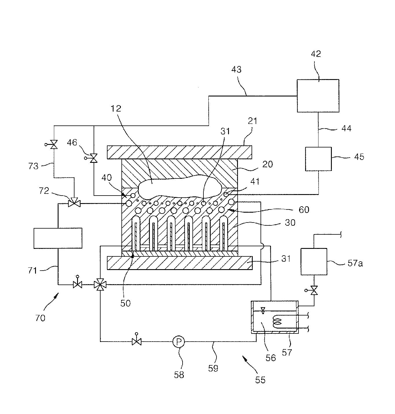
Figure1.1 Weldless-typeinjectionmoldapparatus(24).
cavity12.Thesecondfluidflows51areconnectedtoeachother bycommunicationholes52.Inaddition,thesecondfluidflows 51aresealedbyablockingplate53engagedwiththelowermold 30.Theblockingplate53mayhavepartitioningplates54inserted intothesecondfluidflows51toelongateafluidflowtrackofthe secondfluidflows51.Here,eachofthepartitioningplates54may beshorterthaneachofthesecondfluidflows51.
Thefirstcoolingunit50includesafirstrefrigerantsupplyunit55 forcontinuouslysupplyingcoolanttothesecondfluidflows51. The firstrefrigerantsupplyunit55includesafirstrefrigerant tank57in whichrefrigerant56suchascoolantorcoolingoilisstored,afirst pump58connectingtherefrigeranttank57andthefirstfluidflow 51,andathirdcirculatingconduit59.Thefirstrefrigeranttank57is connectedtoamakeupwatertank57aforrefillingtherefrigerant56. Inaddition,arefrigerantcoolingsystemforcoolingtherefrigerant maybeinstalledinthefirstrefrigeranttank57.
Thethirdfluidflows61andthebranchconduit71maybeconnectedtoeachotherbythefirstcirculatingconduit43ofthe boiler 42andapurgeconduit73,sothattherefrigerantofthirdfluid flows 61maybeexhaustedwhenheatingiscarriedoutbytheheating unit 40.Thesecondcontrolvalve72maybeathree-wayvalveinstalled ataconnectionpartofthepurgeconduit73andthebranchconduit 71tosupplysteamorcoolant.
Imagesoftheuppermoldandthelowermoldduringinjection moldingwereobtainedusingaforward-lookinginfraredcamera. Thiscanillustratetheheatedstatesduringinjectionmolding,as showninFigure1.2.
AsevidentfromthephotographsinFigure1.2,heataccumulated aroundthecavity,whileheatdidnotaccumulateintheupper and lowermolds.Thatistosay,sinceheatisnottransferredtoalowerportionofthecavity,theheatcapacityfortheoverallinjection moldingprocessisnotsohigh.
Sinceheataccumulationispreventedinsuchamanner,acoolingandheatingtimeforinjectionmolding,specificallythe cooling time,canbereduced,therebyshorteningtheoverallcycletimerequiredforinjectionmoldingofaproduct,ultimatelyenhancingthe manufacturingefficiency(24).
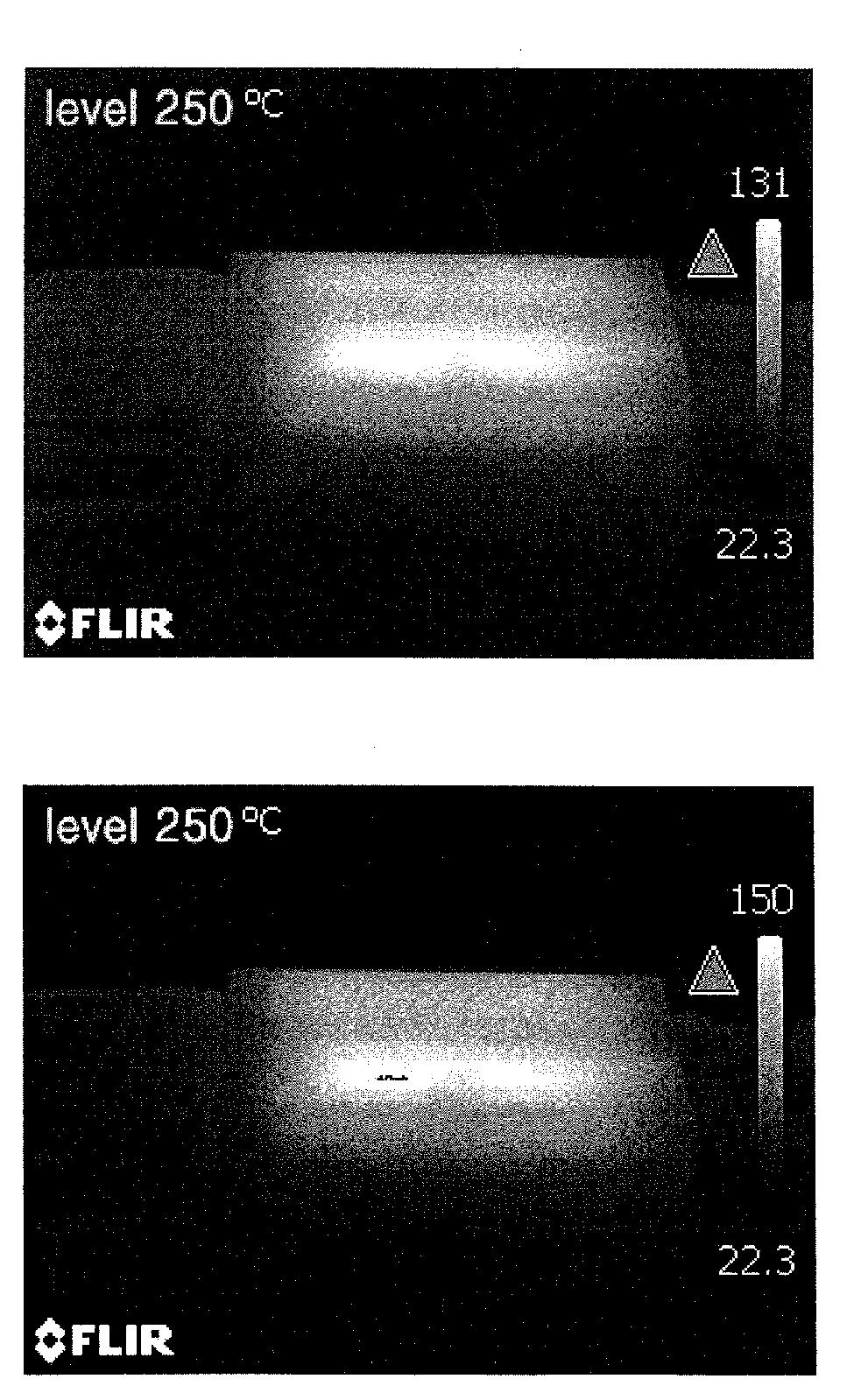
Figure1.2 Heatedstatesduringinjectionmolding(24).