80th Conference on Glass Problems
CeramicTransaction,Volume268
A Collection of Papers Presented at the 80th Conference on Glass Problems
Greater Columbus Convention Center, Columbus, Ohio October 28-31, 2019
Edited by S. K. Sundaram
This edition first published 2021 © 2021 The American Ceramic Society
All rights reserved. No part of this publication may be reproduced, stored in a retrieval system, or transmitted, in any form or by any means, electronic, mechanical, photocopying, recording or otherwise, except as permitted by law. Advice on how to obtain permission to reuse material from this title is available at http://www.wiley.com/go/permissions
The right of S K Sundaram to be identified as the author of the editorial material in this work have been asserted in accordance with law
Registered Office
John Wiley & Sons, Inc., 111 River Street, Hoboken, NJ 07030, USA
Editorial Office
111 River Street, Hoboken, NJ 07030, USA
For details of our global editorial offices, customer services, and more information about Wiley products visit us at www.wiley.com.
Wiley also publishes its books in a variety of electronic formats and by print-on-demand. Some content that appears in standard print versions of this book may not be available in other formats.
Limit of Liability/Disclaimer of Warranty
In view of ongoing research, equipment modifications, changes in governmental regulations, and the constant flow of information relating to the use of experimental reagents, equipment, and devices, the reader is urged to review and evaluate the information provided in the package insert or instructions for each chemical, piece of equipment, reagent, or device for, among other things, any changes in the instructions or indication of usage and for added warnings and precautions. While the publisher and authors have used their best efforts in preparing this work, they make no representations or warranties with respect to the accuracy or completeness of the contents of this work and specifically disclaim all warranties, including without limitation any implied warranties of merchantability or fitness for a particular purpose. No warranty may be created or extended by sales representatives, written sales materials or promotional statements for this work. The fact that an organization, website, or product is referred to in this work as a citation and/or potential source of further information does not mean that the publisher and authors endorse the information or services the organization, website, or product may provide or recommendations it may make. This work is sold with the understanding that the publisher is not engaged in rendering professional services. The advice and strategies contained herein may not be suitable for your situation You should consult with a specialist where appropriate. Further, readers should be aware that websites listed in this work may have changed or disappeared between when this work was written and when it is read Neither the publisher nor authors shall be liable for any loss of profit or any other commercial damages, including but not limited to special, incidental, consequential, or other damages.
Library of Congress Cataloging-in-Publication Data is available
Names: Conference on Glass Problems (80th : 2018 : Columbus, Ohio) | American Ceramic Society, issuing body.
Title: 80th conference on glass problems / The American Ceramic Society.
Description: Hoboken, NJ : Wiley-American Ceramic Society, 2021. | Series: Ceramic transactions; volume 268 | Includes index.
Identifiers: LCCN 2020036165 (print) | LCCN 2020036166 (ebook) | ISBN 9781119744900 (cloth) | ISBN 9781119744917 (adobe pdf) | ISBN 9781119744924 (epub)
Subjects: LCSH: Glass Congresses. | Glass manufacture Congresses. | Glass Defects Congresses. | Glass melting Congresses.
Classification: LCC TP786 .C66 2021 (print) | LCC TP786 (ebook) | DDC 666/.1 dc23
LC record available at https://lccn.loc.gov/2020036165
LC ebook record available at https://lccn.loc.gov/2020036166
Cover design by Wiley Printed in the United States of America. 10 9 8 7 6 5 4 3 2 1
PLENARY SESSION
Of Oxy-Fuel Glass Melting: Oxygen Production, Energy Efficiency, Emissions and CO
(Practical Application of Higher Levels of Electric Heat Input)
W. Kuhn, A. Reynolds, P. Molcan, and B. Malphettes
Reduction with Super Boosting and Advanced Energy Management using Renewable Resources
H. P. H. Muijsenberg, Hans Mahrenholtz, Petr Jandacek, Stuart Hakes, and Christoph Jatzwauk
Designing Furnace Feed Systems That Work
Roger A. Barnum and Scott A. Clement
Ruediger Margraf
Cullet – Another Step Towards Glass Sustainability
Christopher J. Hoyle, Kevin L. Fulkerson, and Brian J. Naveken
REFRACTORIES
New Tuckstone Refractory Solution for Long Life Glass Furnace Superstructure
Isabelle Cabodi, Pierrick Vespa, Thibaut Chuffart, and Michel Gaubil
Optimization and Energy Savings Especially in Container Glass Production by Using a Refractory Coating
Rolf Weigand and Heiko Hessenkemper
Lieke de Cock
Foreword
The 80th Glass Problem Conference (GPC) was organized by the Kazuo Inamori School of Engineering, The New York State College of Ceramics, Alfred University, Alfred, NY 14802 and The Glass Manufacturing Industry Council (GMIC), Westerville, OH 43082. The Program Director was S. K. Sundaram, Inamori Professor of Materials Science and Engineering, Kazuo Inamori School of Engineering, The New York State College of Ceramics, Alfred University, Alfred, NY 14802. The Conference Director was Robert Weisenburger Lipetz, Executive Director, Glass Manufacturing Industry Council (GMIC), Westerville, OH 43082. The GPC Advisory Board (AB) included the Program Director, the Conference Director, and several industry representatives. The Board assembled the technical program. Donna Banks of the GMIC coordinated the events and provided support. The Conference started with a half-day plenary session followed by technical sessions. The themes and chairs of four technical sessions were as follows:
Melting and Combustion
Uyi Iyoha, Praxair, Inc., Peachtree City, GA, Jan Schep, Owens-Illinois, Inc., Perrysburg, OH, and Justin Wang, Guardian Industries, Auburn Hills, MI
Batch, Environmental, and Modeling
Phil Tucker, Johns Manville, Littleton, CO and Chris Tournour, Corning Inc., Corning, NY
Refractories
Larry McCloskey, Anchor Acquisition, LLC, Lancaster, OH and Eric Dirlam, Ardagh Group, Muncie, IN
Sensors and Control
Adam Polycn, Vitro Architectural Glass, Cheswick, PA and Glenn Neff, Glass Service USA, Inc., Stuart, FL
Preface
This volume is a collection of papers presented at the 80th year of the Glass Problems Conference (GPC) in 2019. The GPC continues the tradition of publishing the papers that goes back to 1934. The manuscripts included in this volume are reproduced as furnished by the presenting authors, but were reviewed prior to the presentation and submission by the respective session chairs. These chairs are also the members of the GPC Advisory Board.
As the Program Director of the GPC, I am thankful to all the presenters at the 80th GPC. This year’s meeting was record breaking in many sense. We had a total of 570 registered attendees including 40 students from across the country. I appreciate all the support from the members of Advisory Board. Their volunteering sprit, generosity, professionalism, and commitment were critical to the high quality technical program at this Conference. I also appreciate continuing support and strong leadership from the Conference Director, Mr. Robert Weisenburger Lipetz, Executive Director of GMIC and excellent support from Ms. Donna Banks of GMIC in organizing the GPC. I look forward to continuing our work with the entire team in the future.
Please note that The American Ceramic Society and myself did minor editing and formatting of these papers. Neither Alfred University nor GMIC is responsible for the statements and opinions expressed in this volume.
S. K. Sundaram Alfred, NY
March 2020
Acknowledgements
It is my great pleasure to acknowledge the dedicated service, advice, and team spirit of the members of the GPC AB in planning this Conference, inviting key speakers, reviewing technical presentations, chairing technical sessions, and reviewing manuscripts for this publication:
Kenneth Bratton Bucher Emhart Glass, Windsor, CT
Chris Bloom─Owens Corning, Granville, OH
Weijian Chen Libbey Glass, Toledo, OH
Eric Drilam Ardagh Glass, Muncie, IN
Uyi Iyoha Praxair Inc., Peachtree City, GA
Robert Lipetz Glass Manufacturing Industry Council, Westerville, OH
Larry McCloskey Anchor Acquisition, LLC, Lancaster, OH
Glenn Neff Glass Service USA, Inc., Stuart, FL
Adam Polcyn Vitro Architectural Glass, Cheswick, PA
Jan Schep Owens-Illinois, Inc., Perrysburg, OH
Christopher Tournour Corning Incorporated, Corning, NY
Phillip Tucker Johns Manville, Littleton, CO
James Uhlik─Toledo Engineering Co., Inc., Toledo, OH
Justin Wang─Guardian Industries, Auburn Hills, MI
Finally, I am indebted to Donna Banks, GMIC for her patience, support, and attention to detail in making this conference a big success and this Proceedings possible.
80th Conference on Glass Problems xi
PLENARY SESSION
FUTURE OF OXY-FUEL GLASS MELTING: OXYGEN PRODUCTION, ENERGY EFFICIENCY, EMISSIONS AND CO2 NEUTRAL GLASS MELTING
Hisashi Kobayashi Praxair, Inc.
Danbury, CT 06810
ABSTRACT
Over 300 commercial glass melting furnaces have been successfully converted to oxy-fuel firing worldwide since 1991 when the first full oxy-fuel conversion of a large container glass furnace took place. The main benefits of oxy-fuel conversion are fuel reduction, glass quality improvement, emissions reduction (CO2, CO, NOx, SO2, particulates), and productivity improvements. Significant changes in the melting and fining behaviors were observed under oxy-fuel firing. Most furnaces required some batch modifications to optimize the glass fining chemistry and to control foam. Improved oxy-fuel burner and furnace designs have reduced alkali volatilization and silica crown corrosion. Silica crown is expected to last for a full furnace campaign, especially with new no-lime silica bricks. Today most of high-quality specialty glass products such as LCD display glass and fiber glass are melted in oxy-fuel fired glass furnaces. Oxy-fuel conversion of large soda lime glass furnaces, however, has been limited to about sixty container and ten float/flat glass furnaces due to the additional cost of using oxygen. Key factors to improve the economics of oxy-fuel fired such as efficiency of air separation technology and waste heat recovery are reviewed. The potential of using hydrogen and renewable fuels with oxygen to reduce CO2 emissions is also discussed. (key words: oxy-fuel, glass melting, CO2 reduction, hydrogen combustion)
INTRODUCTION
In 1988, the U.S. Department of Energy awarded a program to Praxair, Inc. (a member of the Linde group now) to demonstrate the use of oxy-fuel combustion in a large commercial glass furnace using an on-site vacuum-pressure swing adsorption (VPSA) technology. A container glass furnace at Gallo Glass Company was rebuilt in 1991 as the first large scale oxy-fuel fired furnace1. The successful conversion of the furnace and the demonstration of significant fuel savings (15%) and emissions reduction (80% reduction in NOx and CO, and 30% particulates) stimulated the glass industry to adopt the new technology at a rapid rate. By 1996 about 90 commercial glass furnaces were converted to oxy-fuel firing worldwide2. Although the rate of oxy-fuel firing conversions slowed down since then, over 300 commercial glass furnaces are fired with oxygen today. Most of specialty glass furnaces such as LCD glass furnaces are fired with oxygen as high glass melting temperature, relatively small furnace size and the high glass quality requirement made oxy-fuel firing more economic. Over one hundred insulation and reinforcing glass fiber furnaces have been converted to oxygen firing as large fuel savings are achieved when air fired recuperative furnaces are converted to oxy-fuel firing. About fifty container glass furnaces and about ten float/flat glass furnaces have been converted for NOx reduction, production rate increase, and capital cost reduction.
Most of fuel efficiency gains of oxy-fuel fired furnaces come from the elimination of nitrogen contained in combustion air (i.e., about 78% N2 and 1% Ar by volume) and the corresponding reduction in the flue gas sensible heat loss3. Fuel savings of 5 to 50% have been achieved without using any flue gas heat recovery systems under oxy-fuel firing as compared with
0th Conference on Glass Problems, Ceramic Transaction Volume 268 , First Edition. Edited by S. K. Sundaram. ©2021 The American Ceramic Society. Published 2021 by John Wiley & Sons, Inc
various air fired furnaces. Fuel savings achievable by oxy-fuel conversion depend on the type of heat recovery systems used in the air fired furnaces and their conditions. About 10 to 15% fuel savings have been achieved on the furnace campaign average for large container and float glass furnaces equipped with efficient regenerators to preheat combustion air to about 1300C. The efficiency of regenerators deteriorates with furnace age due mainly to deposits build up in the regenerator passage and to increase in air infiltration4. For example, specific fuel consumption for an air fired regenerative furnace may increase by 16% over 12 years (i.e., 1.35% per year)5, while that for oxy-fuel fired furnace without heat recovery may increase only by 6% over 12 years. Thus, fuel savings by oxy-fuel firing is relatively small in early furnace campaign and increases as the furnace ages. For fiber glass furnaces with metallic recuperators fuel savings by oxy-fuel conversion are typically in a range of 30 to 50%. Metallic recuperators can preheat combustion air only up to about 800C and the furnace energy efficiency is significantly lower than the furnaces equipped with regenerators. For small specialty glass furnaces operating at high temperatures, fuel savings over 50% have been achieved in some furnaces since small recuperators and regenerators are not very efficient.
Reduction of NOx emissions was an important benefit and an economic driver for oxyfuel conversion, especially in the U.S.. Due to the high furnace temperature required for glass melting significant “thermal NOx” is formed in the flame region. The rate of formation of thermal NOx is strongly temperature dependent and approximately proportional to the concentration of nitrogen in the furnace. The conversion of an air fired furnace to oxy-fuel firing typically results in NOx reduction by 80 to 90% as the nitrogen concentration in the furnace is reduced from about 70% in the air fired furnace to about 5 to 10% in typical oxy-fuel fired furnaces. Other key factors influencing NOx emission are oxy-fuel burner design which influences the peak flame temperature, excess oxygen and batchs niter content 6 .
Melting and fining behaviors change significantly under oxy-fuel firing due to the interaction between the furnace atmosphere and glassmelt and changes in the heat transfer characteristics. The concentration of water vapor in the furnace atmosphere is about 16-18% in the air-natural gas fired furnace, which increases to 50-55% in the oxy-fuel fired furnace. Higher water vapor concentration increases water dissolution into glassmelt and enhances fining reactions7. Extensive laboratory studies and mathematical modeling have been conducted to investigate heat transfer, glass fining, alkali volatilization and refractory corrosion mechanisms under oxy-fuel firing. Most furnaces required some batch modifications to optimize the glass fining chemistry8. Although accelerated silica crown corrosion was experienced in early conversions, improved burner and furnace designs and the development of new silica crown materials with low of no lime extended the life of the silica crown close to that of a conventional air fired furnace9-10. A review paper11 describes technical differences between oxy-fuel fifing and the air-firing in more details.
Recent advances in oxygen production and oxy-fuel technology aim to make oxy-fuel glass melting a more cost-effective solution to meet the sustainability goal of CO2 reduction. For example, the efficiency of air separation technology has improved and the power consumption to produce oxygen has decreased significantly. Advanced waste heat recovery technologies for oxy-fuel fired furnaces have also been developed to reduce the fuel and oxygen requirement for oxy-fuel furnaces1214. Oxy-hydrogen combustion is considered a leading option for glass melting of future. This paper reviews the key economic factors of oxy-fuel glass melting and discusses the future of oxy-fuel combustion for CO2 neutral glass melting.
ECONOMICS OF OXY-FUEL FIRING
The economics of oxy-fuel conversions depends mainly on the fuel savings achievable, fuel cost and oxygen cost for operating cost comparison. The value of fuel savings needs to be greater than the cost of oxygen to achieve a net saving in the operating cost when other oxy-fuel benefits such as NOx reduction and production rate increase are not considered. Many air fired furnaces less than 100 tpd capacity were converted to oxy-fuel firing as the small waste heat recovery systems, especially recuperators, are not very efficient and large fuel savings of 40-50% were achieved. For large container and float glass furnaces with efficient regenerators about 10 to 15% fuel savings have been achieved on the furnace campaign average. The economic drivers for the conversion were capital cost savings of eliminating regenerators, especially for green field projects, furnace capacity increase, and NOx reduction.
Figure 1 compares the fuel and oxygen costs for a generic 300 mtpd (metric ton per day) container glass furnace with 50% cullet and no electric boosting at three different fuel costs of 5, 10 and 15 dollars per MMB tu HHV (million Btu in higher heating value) and at a constant oxygen cost of $50/ston (short ton) . For the typical natural gas composition represented as methane, one short ton of O2 is required to combust about 12 MMBtu (HHV) of natural gas. The baseline specific fu el consumption for the air fired furnace with regenerators is 4 MMBtu/ston and fuel a nd oxygen savings of 10% and 30% are assumed for oxy-fuel firing without heat recovery (“Oxy”) and oxy-fuel firing w ith heat recovery (“Oxy-HR”) respectively. At the low fuel cost of $5/MMBtu th e baseline melting cost is $20/ston of glass. With 10% fuel savings the specific fuel co st and the oxygen cost are $18 and $15 per ston of glass respectively. The combin ed cost of $33 per ston is higher than the baseline cost. Even with 30% fuel savings achieved by using a flue gas heat recovery system with oxy-fuel firing the combined cost of melting increases by $5.7/ston. At $10/MMBtu the melting cost of Oxy-HR becomes slightly less than th e air case and at a high fuel cost of $15/MMBtu about $5/ston savi ngs in melting cost is projected with OxyHR. This example illustrates that achieving hi gh fuel savings and reducing oxygen cost are key economic factors to make oxy-fuel glass me lting as the economic choice in the future.
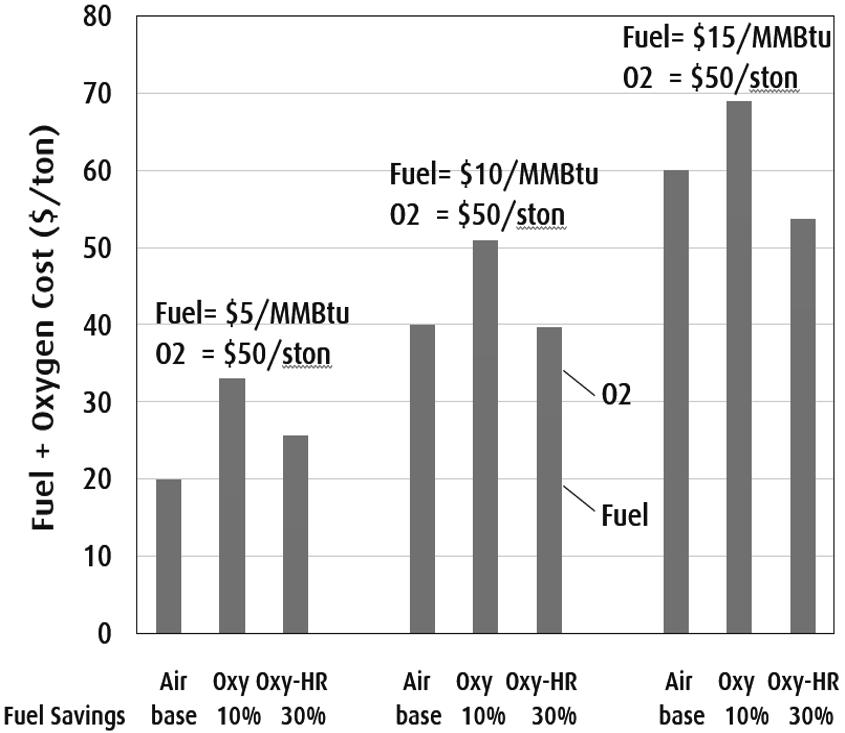
Figure 1. fuel and oxygen costs for a generic 300 mtpd (metric ton per day) container with 50% cullet and no electric boostingg
OXYGEN GENERATION TECHNOLOGY
Oxygen for glass furnace conversion applications is typically supplied by the on-site oxygen generation system using a vacuum-pressure swing adsorption (VPSA) technology and backed up with delivered liquid (LOX) in a storage tank. Most of oxy-fuel fired flat glass furnaces use cryogenic air separation systems as the nitrogen co-produced from the cryogenic separation system is used for the float tank. Cost of oxygen is highly site specific and involves many factors including the plant size, electric power cost, VPSA equipment, manufacturing, construction, engineering and operation. Electric power cost is typically the most important cost element and constitutes about 1/3 to 2/3 of the overall oxygen cost depending on the power cost and the plant size. Advancements in the air separation technology have reduced the power required to separate air to make oxygen (kwh/ton O2) over the years. Figure 2 shows a historical trend and expectation for future in a relative scale by assigning 100% for year 2019. Specific power consumption was about 40% higher in 2000. The trend is likely to continue and further improvements of 20-30% reduction are expected in the next 5 to 10 years.
ENERGY EFFICIENCY IMPROVEMENTS FOR FUTURE
In a large oxy-fuel fired glass furnace without flue gas heat recovery about 25-30% of the heat generated by combustion is lost in the sensible heat of flue gas and the balance is available in the furnace to melt glass batch/cullet and to compensate for the wall heat losses. Figure 3 shows projected improvements on specific fuel consumption for a 300 tpd oxy-fuel fired container glass furnace with 50% cullet and no electric boost. Without any flue gas heat recovery the baseline fuel consumption is 3.7 GJ LHV/t (lower heating value per metric ton or 3.52 MMBtu HHV/ston) for this state-of-the-art oxy-fuel fired furnace. The electric energy consumption for oxygen production is assumed to be 250 kWh/t O2 generated and the primary fuel required to produce the electricity was assumed to be 9 MJ/kWh at 40% electric power generation efficiency. With the assumed primary fuel required to make oxygen overall fuel consumption becomes 4.3 GJ/t. With a full flue gas heat recovery system to reduce flue gas temperature to 250 C specific fuel consumption of 2.85 GJ/t is projected and the oxygen requirement is reduced proportionally.
Figure 2. Historical trend of specific electric power consumption to make VPSA oxygen
Further improvements in fuel consumption requires new innovations to reduce wall heat losses and power consumption for oxygen generation. If 50% reduction in wall heat losses and 30% reduction in the power consumption for oxygen generation are achieved in the future, fuel consumption is projected to be 2.43 GJ/t without considering the fuel energy to make oxygen and 2.70 GJ/t with the assumed primary fuel for oxygen generation added. If the electric power is generated by renewable sources such as wind and solar, no fuel is required to produce oxygen. We may consider 2.5 GJ/t (2.38 MMBtu HHV/ston) as the goal for future.
Various flue gas heat recovery systems for oxy-fuel fired furnaces have been developed and installed in several commercial furnaces. They include batch-cullet preheaters, oxygen-fuel preheaters and thermo-chemical regenerators. Fuel consumption as low as 3 GJ/t has been achieved in commercial container glass furnaces12-18. Thus, good flue gas heat recovery is achievable today and the main engineering challenge is to reduce the capital costs to improve the economics. The goal of reducing wall heat losses by 50% may be more challenging with the current furnace design. Heavy insulation layers have already been applied to furnace walls and crown and the total wall thickness of hot face refractory and the insulation layers are more than 800 mm for some furnaces. Adding more insulation layers does not appear to be practical. In the typical furnace design about a third of the total wall heat losses is from uninsulated wall areas19, especially from the air-cooled metal lines. Innovative designs to reduce heat losses from uninsulated wall areas such as metal lines, skew blocks and tuck stones are required. Another design approach to reduce wall heat loss per ton of glass is to design a rapid melting system with very small total wall areas. The maximum pull rate of the current container furnace design is about 4 tpd/m2, often assisted with electric boost. If the specific pull rate is increase to about 10 tpd/m2, then the total wall area would be reduce to about ½. In a pilot scale test of a rapid melter with oxy-fuel roof fired burners melting rates as high as 25 tpd/m2 have been demonstrated by operating the furnace temperature above 1700 C20. A pilot scale rotary glass melting furnace with spray water cooled wall was demonstrated to withstand the very high furnace temperature20. Submerged combustion melter with water cooled walls is another approach to rapid melting21. Although water cooled walls have very high specific heat loss, small wall area may make the total wall heat losses less than that of the current furnace design.
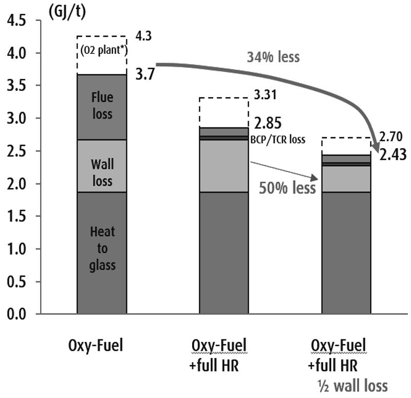
3. Potential improvements in specific fuel consumption for a 300 mtpd container furnace with 50% cullet.
Figure
CURRENT CO2 EMISSIONS FROM GLASS PRODUCTION
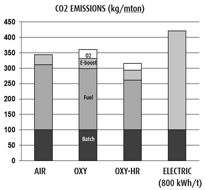
Figure 4 compares CO2 emissions from a 300 tpd container glass furnace with 50% cullet using 1,000 kW of electric boost. Specific fuel consumptions assumed are 4.0 GJ/t for air firing, 3.8 GJ/t for oxy-fuel firing (“OXY”), 3.1 GJ/t for oxy-fuel firing with heat recovery (“OXY-HR”), and 800 kWh/t for full electric melting21. The CO2 emission from decomposition of soda ash and limestone/dolomite in the batch contributes about 100 kg/t for each case. CO2 emission from natural gas combustion contributes about 210 kg/t for the air fired furnace, 200 kg/t for OXY and 160 kg/t for OXY-HR. CO2 emissions from electric power generation range from zero for renewable power such as wind and solar to as high as 1.0 kg/kWh from an old coal fired power plant. The average CO2 emission in the U.S. was about 0.5 kg/kWh in 2015 and about 0.4 kg/kWh in EU in 2011. In this analysis CO2 emission rate of 0.4 kg/kWh was assumed. 1,000 kW of electric boost contributes 32 kg/t of CO2 emission. The electric power required for oxygen generation also contributes to the overall CO2 emission. At an assume electric power requirement of 250 kWh per ton of oxygen generation additional CO2 emissions of 29 and 23 kg/t come from OXY and OXY-HR respectively. For the full electric melter with 800 kWh/t of power consumption CO2 emission becomes 320 kg/t and the total CO2 emission 420 kg/t, which is higher than those from the natural gas fired furnaces by about 15 to 35%.
In order to achieve 90% reduction in CO2 emissions in the future all these sources of CO2 emissions have to be substantially reduced. Raw materials have to be mostly free of carbonate materials such as cullet. For container glass manufacture cullet ratios as high as 90% are already used in some furnaces and the trend for higher cullet uses will continue. Electric power has to be either generated from renewable sources or nuclear plants and CO2 emissions from fossil fuel burning power plants have to be captured and sequestered. For fuel fired glass melting furnaces biomass derived fuels or hydrogen made without CO2 emissions need to be used.
HYDROGEN AND BIOMASS DERIVED FUELS FOR REDUCING CO2 EMISSIONS
Hydrogen is considered as the fuel of future to eliminate CO2 emissions from combustion of hydrocarbon fuels. Large scale demonstration projects have been announced in EU. For example, existing natural gas distribution pipelines are proposed to be converted to distribute compressed hydrogen in Leeds, UK24. On a volume basis hydrogen has a lower heating value (LHV) of 10.8
80th Conference on Glass Problems 8
Figure 4. Comparison of CO2 emissions from 300 tpd container glass furnaces at 50% cullet
MJ/Nm3 @ 0 C (275 Btu/scf @ 60F) as compare with 35.8MJ/Nm3 (913 Btu/scf) for methane. For the same heat input the volume flow rate of hydrogen becomes 3.2 times greater than that of methane or typical natural gas. For oxy-fuel combustion hydrogen has an advantage over natural gas as the oxygen requirement for combustion to generate the same amount of heat (LHV) is reduced by about 17%. Hydrogen has a wider flammability range and a higher adiabatic flame temperature as compared with methane. For glass furnace combustion applications hydrogen flame is non-luminous, but the radiation heat transfer is excellent because the water vapor concentration of combustion gases is near 100%, which enhances gas emissivity of oxyhydrogen flame and combustion gases. The conversion of the existing natural gas firing system to hydrogen firing requires fuel piping and burner modifications, but no fundamental heat transfer issues are expected with a proper oxy-hydrogen burner design. As experienced in the conversion of air-fired furnace to oxygen firing, higher water vapor concentration in the furnace atmosphere is expected to increase the water dissolution into glassmelt and to enhance the fining reactions7-8. Reduction of batch fining agents is recommended23 to compensate for the enhanced fining reactions and to control foam generation.
Table 1 compares hydrogen and biomass derived fuels with natural gas (as pure methane) for glass melting applications25. For each fuel specific fuel and oxygen consumptions were calculated for a typical 300 mtpd container furnace with 50% cullet and compared. The baseline specific natural gas and oxygen consumptions were 3.87 GJ/t and 220 Nm3/t respectively. Approximate fuel costs are also compared assuming $8/GJ LHV for natural gas which was a typical cost in EU in 2018. Most of hydrogen used today is made from natural gas by the steammethane reforming (SMR) process. Typical hydrogen yield is about 70% based on the lower heating value of hydrogen (LHV) as compared with the LHV of natural gas input. The cost of hydrogen made from natural gas is roughly twice that of natural gas and assumed to be $15/GJ. The cost of CO2 capture and sequestration (CCS) from the SMR process is not included. Both hydrogen and oxygen can also be made by the electrolysis of water using renewable electric power. According to a report by IEA26 the project cost of hydrogen in 2030 made by electrolysis is about $2 to $4 per kg of H2 as compared with about $1.4 to $3 per kg of H2 made from the SMR process with CCS. The large variations are mostly due to regional variations in the renewable power cost and the natural gas cost. The specific fuel consumption with oxy-hydrogen firing increases by about 1% as compared with oxy-methane firing and the specific oxygen consumption is reduced by 15%. The main challenge of using hydrogen for glass melting is its projected high cost. As shown in Figure 1 oxy-fuel firing is likely to be more favored than air firing at $2 per kg of H2. ($2 per kg of H2 corresponds to $16.7 per GJ LHV or $17.6 per MMBtu LHV).
Digester gas is produce from anaerobic digestion of organic materials such as pig and cow manures and municipal waste water sludge. Typical composition is about 60% methane and 40% carbon dioxides by volume. The existing natural gas firing system can be modified to fire compressed digester gas. Both the specific fuel and oxygen consumptions are projected to increase by 10%. Digester gas is typically priced less than natural gas and assumed to be $6 per GJ, but the availability is limited to the proximity of local digesters. Liquid fuels produced from biomass include ethanol and pyrolysis oil. Biomass based ethanol is produced from corn, sugar cane and other crops in large quantities for gasoline blends. In the U.S. over 1 million bbl/day of corn ethanol was produced in 2017. It is enough to produce 400 million tpy of container glass at 4 GJ/t, which is more than three times the world container glass production. Fuel and oxygen requirements are similar to the natural gas fired system. Although the existing natural gas firing system can be
modified to fire ethanol, high cost of fuel is the major hurdle at present. Pyrolysis oil is produced from wood and other biomass by a thermal decomposition process optimized to produce liquid products containing various oxygenated hydrocarbon compounds and water. Heating value is about 16 MJ LHV/kg with 25% water content corresponding to about 60% of LHV of ethanol (27.7 MJ/kg). When fired with oxygen about 20% more heat input is required as compared with natural gas.
Table 1. Fuel and oxygen consumption and cost of biomass derived fuels relative to natural gas for an oxy-fuel fired 300 mtpd container furnace at 50% cullet without electric boost
Solid fuels such as wood chips, wood char and torrefied wood can be fired with oxygen in glass furnaces. Since pulverized petroleum coke has been used in glass melting furnaces, there is no fundamental technical barriers to use solid biomass fuels as long as ash quality is compatible with the quality of glass produced. Solid fuel firing, however, requires a pulverization step and a special solid fuel feeding and distribution system and the conversion from a natural gas fired system is more involved. Dry wood with 5% moisture requires about 20% more fuel and oxygen as compared with natural gas. Torrefied wood is produced in a mild roasting process and is an excellent dry fuel. Fuel requirement is the same as natural gas and the oxygen requirement is reduced by about 12%.
SUMMARY
Over 300 oxy-fuel fired glass melting furnaces operate worldwide today and provide the benefits of fuel reduction, productivity increase and NOx reduction. For wider adoption of oxy-fuel firing the reduction of fuel and oxygen consumption and the cost of oxygen generation is required. Several oxy-fuel fired furnaces have been equipped with flue gas heat recovery systems and specific fuel consumption as low as 3 GJ/t (2.8 MMBtu/ston) have been demonstrated in container furnaces. The goal of 2.5 GJ/t (2.4 MMBtu/ston) is considered to be technically feasible with 50% reduction in wall heat loss combined with flue gas waster heat recovery. For CO2, neutral glass melting of future
hydrogen and biomass derived fuels can be used with oxygen for glass melting. There are no major technical barriers in using hydrogen for glass melting and oxygen-firing is likely to be favored over air-firing due to expected high hydrogen costs and the reduced specific oxygen requirement with hydrogen combustion.
REFERENCES
1. Tuson, G. B., Higdon, R., and Moore, D., "100% Oxygen Fired Regenerative Container Glass Melters," Glass 91 52nd Conference on Glass Problems, University of Illinois at Urbana - Champaign, IL, November 12 to 13, 1991.
2. Ronald W. Schroeder of Praxair, Inc., and Allan E. Zak of Corning, Inc., "Oxy-Fuel Economics Update Based on Case Histories” the 56th Conference on Glass ProblemsOctober 1995 at the University of Illinois/Champaign-Urbana
3. Kobayashi, H., "Oxygen Enriched Combustion System Performance Study," Vol. I Technical and Economic Analysis. Prepared for U. S. Dept. of Energy Idaho Operations Office, Idaho Falls, ID, Report No. DOE/ID/12597, March 1987.
4. Beerkens, R.G.C.,”The Most Energy Efficient Glass Furnace: Energy Efficiency Benchmarking and Energy Saving Measures for Industrial Glass Furnaces”, A.T.I.V. Conference - Parma (Italy), 2006
5. Beerkens, R.G.C., H. Van Limpt, ”Energy Efficiency of Glass Furnaces” , Presented at GMIC Workshop on Evolutionary and Revolutionary Strategies for Keeping Glass Viable through the 21st Century”, July 30-31, 2003, Rochester, NY
6. Kobayashi, H., G. B. Tuson and E. J. Lauwers, "NOx Emissions from Oxy-Fuel Fired Glass Melting Furnaces," European Society of Glass Science and Technology Conference on Fundamentals of the Glass Manufacturing Process, Sheffield, England, September 9-11, 1991.
7. Beerkens, R.G.C., Laimbock, P., A.J. Faber, and Kobayashi, H., "Interaction between furnace atmospheres and sulfate fined glass melts", Proceedings of XVIII International Congress on Glass, July 5-10, 1998, San Francisco, CA, USA
8. Kobayashi, H., and Beerkens, R.G.C., "Reduction of SO2 Emissions of Oxy-Fuel Firing –Water Enhanced Sulfate Fining," Fifth International Conference on Advances in the Fusion and Processing of Glass, Toronto, Canada, July 27-31, 1997
9. Whittemore, D.S., R.F. Spaulding, H.E. Wolfe, and J.T. Brown, “New Silica Refractory for Oxy-Fuel Glass Melting”, J. Int. Glass, vol.102, pp120-124, 1999
10. Gonzalez, A.R., J.T. Brown, R.P. Weilacher, and M.A. Nelson, “Review of Improved Silica Crown Refractory and Practices for Oxy-Fuel Fired glass Melters”, 64th Conference on Glass Problems, University of Illinois at Urbana – Champaign, IL, October 28-29, 2003.
11. H. Kobayashi, “Advance in Oxy-Fuel Fired Glass Melting Technology”, Proceedings of XX International Congress on Glass, Sep. 26-Oct.1, 2004, Kyoto Japan
12.M. van Valburg, E. Sperry, S. Laux, R. Bell, A. Francis, and H. Kobayashi, “Design and Implementation of OPTIMELT™ Heat Recovery for an Oxy-Fuel Furnace at Libbey Leerdam”, 78th Conference on Glass Problems, Columbus, OH, October, 2017.
13. M. van Valburg, F. Schuurmans, E. Sperry, S. Laux, R. Bell, A. Francis, S. Chakravarti and H. Kobayashi, “Operating Experience with the OPTIMELT™ Heat Recovery Technology on a Tableware Glass Furnace”, 79th Conference on Glass Problems, Columbus, OH, October, 2018.
14. Goruney,T., Arzan,N., et.al., “Oxy-fuel Tableware Furnace with Novel Oxygen and Natural Gas Preheating System”, 77th Conference on Glass Problems, Columbus, OH, November 8, 2016.
15. Barrickman, L., Leone, P., “Leone Industries: Experience with Cullet Filter /Preheater,” 67th Conference on Glass Problems, Columbus, OH, October 31 to November 1, 2006.
16. Lubitz,G., Beutin, E.F., Leimkuhler, J., “Oxy-fuel fired furnaces in combination with batch and cullet preheating”, Proceedings of Novem Energy Efficiency in Glass Industry. Ed. Th. Nohlmans, L. Moonen, and R. Beerkens. Amsterdam. The Netherlands l8.-I9. May 2000
17. Schroeder, R.W., Kwamya, J.D., Leone, P., Barrickman, L., “Batch and Cullet Preheating and Emissions Control on Oxy-Fuel Furnaces,” 60th Conference on Glass Problems, University of Illinois at Urbana, October 19 to 20, 1999.
18. Snyder, W.J., Chamberland, R.P., Steigman, F.N., and Hoyle, C.J., “Economic Aspects of Preheating Batch and Cullet for Oxy-Fuel Fired Furnaces,” 61st Conference on Glass Problems, Ohio State University, October 17 to 18, 2000.
19. Lindig, M,. “Energy savings and furnace design”, 73rg Conference on Glass
20. Kobayashi,H., LeBlanc,J.L.,”Oxy-fuel Fired Rapid Glass Melting Furnace”, Third International Conference in Advances in the Fusion and Processing of Glass, New Orleans, LA, June 10-12 1992
21.Rue,D., and Brown, J.T., “Submerged Combustion Melting of Glass” International Journal of Applied Glass Science 2 [4] 262–274 (2011)
22. Lindig, M,. “Glass melting technology addressing the environment trend - Electro”, Glastechnische Tagung Der DGG, 29-31May, 2017.
23. U.S. Patent U.S. Patent 5,922,097 (July 13,1999), “Water Enhanced Fining Process- A Method to Reduce Toxic Emissions from Glass Melting Furnaces”, H. Kobayashi and R.G.C. Beerkens
24. “The H21 Leeds City Gate project report”, July 2016, https://futureofgas.uk/ documents/h21-leeds-citygate-project/
25. Kobayashi, H. and Chakravarti,S., “Oxy-Fuel Combustion toward CO2 Neutral Glass Production” Glass Trend Seminar by CelSian, Wurzburg, April 2018
26. International Energy Agency, “The Future of Hydrogen – Seizing today’s opportunities” Report prepared by IEA for the G20, Japan, June 2019
PECULIAR WEAR BEHAVIOR OF SODA LIME SILICATE GLASS IN HUMID AIR AND ITS IMPLICATIONS
Nisha Sheth
Vitro Architectural Glass
Cheswick, PA, 15024, USA
Seong H. Kim
The Pennsylvania State University University Park, PA 16802, USA
ABSTRACT
Soda lime silicate glass shows unusual wear and scratch behavior as a function of humidity. Under moderate wear conditions, the surface damage produced is entirely through the interfacial shear along a direction tangential to the surface. In contrast, severe wear tends to occur at much larger contact pressures resulting in damage due to indentation and shear stress (e.g. scratching). In dry environments under moderate wear conditions, soda lime glass is easily abraded by harder counter surface materials. Yet, in humid environments, soda lime silicate glass has unusually high wear resistance to counter-surface materials that are significantly harder or more chemically durable. This high wear resistance of soda lime glass can be attributed to mechanically induced chemical reactions that may suppress shear-induced damage. In the past, the high wear resistance of soda lime glass has been attributed to leachable sodium ions that may participate in suppressing shear-induced damage. Yet, recent work casts doubt on this hypothesis. Heat strengthened soda lime glass is highly susceptible to wear and scratching, indicating that wear behavior cannot be exclusively attributed to leachable sodium ions. Instead, it was hypothesized that the strained SiO network becomes more susceptible to shear-induced hydrolysis resulting in greater damage under moderate wear conditions at high humidity. Under severe wear conditions in the presence of water, heat strengthened glass is also more susceptible to time-delayed chipping compared to annealed glass. It was hypothesized that the more open silicate network structure of heat strengthened glass may increase the transport kinetics of molecular water to critical sub-surface flaws. This may result in sub-critical crack growth of sub-surface lateral cracks resulting in timedelay chipping along the width of the scratch.
INTRODUCTION
In the last century, glass for window applications has gained increased utility due to technological advancements in processing. Strengthening treatments, such as thermal tempering, have addressed durability and safety concerns of brittle and fragile glass windows. Thermal tempering also increased the strength to weight ratio for glass materials that can lead to lower costs associated with transportation. Recent technological advancements in coatings have enabled architectural glass manufacturers to more precisely control visible light transmission through buildings, filter solar radiation, and provide better thermal insulation allowing for more energyefficient buildings and increased comfort for building occupants. However, anecdotal and empirical evidence shows that heat strengthened glasses have a greater sensitivity to scratching than annealed glasses.[1,2] Since scratches can act as stress concentrators and may grow larger under applied load, damage-resistance is critical for applications that require high strength. 0th Conference on Glass Problems, Ceramic Transaction Volume 268 , First Edition. Edited by S. K. Sundaram. ©2021 The American Ceramic Society. Published 2021 by John Wiley & Sons, Inc
Furthermore, for value-added glazing products, such as low emissivity insulated glazing units (IGU), surface damage and the associated replacement can be costly.
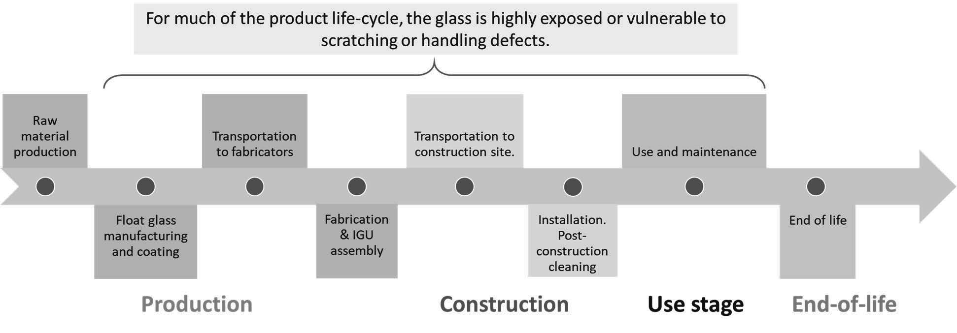
For much of the architectural glazing product lifecycle (Figure 1), glass products are frequently exposed and become vulnerable to scratching defects that can compromise their aesthetics, functionality, and strength. During construction and use, glass is exposed to both organic debris (such as adhesives) and inorganic debris (such as concrete overspray and welding spots). Post-construction cleaning to remove accumulated construction debris is often challenging—requiring harsher cleaning techniques at the risk of scratching the glass surface. This is especially true for tempered glass that appears to be highly scratch-sensitive.
The Glass Committee of the International Window Cleaning Association (IWCA), a trade organization for the health and safety of professional window cleaners, suggested protocols for cleaning architectural glass post-construction and recommend glass scratch liability waivers for all window cleaning contracts, especially for cleaning tempered glass. Since anecdotal and empirical evidence shows that tempered glass could be scratched more easily than annealed glass, many window cleaners concerned about post-construction cleaning of tempered glass requested glass scratch liability waivers. Even then, making scratches on heat strengthened glass could cost millions of dollars due to the replacement of damaged glass products and lawsuits. At times, window cleaners are blamed for the damages that are attributed to metal scrapers and harsh cleaning techniques. Other times, fabricators may also be blamed for the damages attributed to hard-to-see “abrasive fabrication debris” that are difficult to clean with a standard scraper without scratching the glass.
Currently, there are no viable solutions to this issue. Professional window cleaners claim that there are no suitable alternatives to metal scrapers to remove paint, stickers, or adhesives due to health, time, and ergonomic concerns. Furthermore, they argue that metal scrapers are typical and infrequently scratch glass. Instead, window cleaners often suggest that the air-side and tin-side “feel” different with one side “feeling” and “sounding” grittier and having more “drag”. Fabricators claim that there is no method to test for fabrication debris that may become fused to the glass as it is in contact with the rollers in the tempering furnace. Microscope images have not been able to properly capture any supposed fabrication debris.
Figure 1. Architectural glazing product lifecycle.
From a scientific perspective, this issue can be described as a tribological problem—the study of the interaction of sliding surfaces including friction, lubrication, and wear. It becomes critical to understand how thermal treatments, such as heat strengthening, influence the wear behavior of the glass surface with various counter surface materials (organic and inorganic) in various chemical environments. The purpose of this paper is to review the scientific work on this topic and discuss future directions that the glass community ought to explore.
WEAR OF THE GLASS SURFACE
Wear depends on not only the intrinsic properties of glass, but also various extrinsic conditions of the tribo-test system: contact pressure, speed, cycles, lubrication, chemical environment, contact geometry, and generated wear debris as well as surface conditions of the substrate and counter-surface. [2–5] Based on these conditions, moderate or severe wear types can be produced. Under moderate wear conditions, surface damage is induced by a smooth counter surface under a mechanical load that is much less than the indentation damage threshold. In this way, the surface damage produced is entirely through the interfacial shear along a direction tangential to the surface. It is assumed that minimal sub-surface damage occurs during moderate wear in humid environments. However, this assumption needs to be tested and verified for each tribosystem independently by, for example, using cross-sectional microscopy.
In contrast, severe wear type tends to occur at much larger contact pressures resulting in both indentation-induced deformation and deformation due to shear force (i.e. scratch). As a result, the loading rate also influences the wear behavior of the tribosystem. Various deformation and fracture types occur below the sliding contact area due to the spatially-dependent magnitudes of shear stress extending into the sub-surface.[6] As a result, surface abrasion, chipping, and surface and sub-surface cracking are observed due to high normal and shear loads. An example of a severe wear type is a scratch resulting from mechanical damage from a relatively sharp point of contact between the counter-surface and substrate. The applied normal load, geometry and surface condition of the counter-surface, and the surface condition of the substrate determine the width of the wear track due to chipping that occurs along a scratch.
SODA LIME GLASS RESISTANCE TO MODERATE WEAR
Referred to as Reye Archard Khrushchov wear criterion, it is intuitively believed that harder materials scratch softer materials. In dry environments (0% relative humidity (RH)) and under moderate wear conditions, hard counter-surfaces, such as Si3N4, Al2O3, stainless steel, or Pyrex borosilicate glass, can mechanically abrade soda lime silicate glass substrates. This mechanical abrading leaves deep and rough wear tracks even if the counter-surface is smooth and the applied contact load is lower than the indentation damage threshold of the substrate glass.[7]
In a humid environment under moderate wear conditions, the Reye Archard Khrushchov relationship breaks down—moderate wear behavior becomes complex and hardness is no longer the dominant factor determining wear outcomes. Glass substrates that have significantly higher hardness, mechanical strength, and chemical durability are not necessarily more resistant to surface damages during moderate wear test conditions in humid environments. As humidity increases, the substrate wear resistance decreases for fused quartz,[8] alkali borosilicate (Schott BF33),[9] barium boroaluminosilicate (Schott AF45),[9] sodium aluminosilicate,[10] and K+-exchanged sodium aluminosilicate (Corning Gorilla-2),[10] against a borosilicate (Pyrex) counter-surface. In contrast, as the humidity increases, soda lime glass shows increasing wear resistance. Near the saturation vapor pressure, soda lime glass shows high wear resistance with minimal surface damage regardless of the counter-surface materials, such as Si3N4, Al2O3, stainless-steel,[7] and 80th
Pyrex borosilicate,[1,8–10] that are polished flat. It is interesting to note that regardless of the soda lime glass manufacturer, composition or thickness, wear-resistance at high humidity under moderate wear conditions was observed. Soda lime glasses tested include melt-derived green container glass from Owens-Illinois, 0.7- and 1.0-mm thick float glass from AGC, 4 mm float glass from PPG (now Vitro), 10 mm thick Guardian glass, and microscope slide glass from an unknown manufacturer. Table 1 describes the moderate wear characteristics of various substrates and counter-surface materials near saturation vapor pressure (90% RH).
Table 1. Summary of moderate wear behavior of the glass substrate in high humidity (RH 90%) environments for various tribosystems.
Counter-surface
Substrate Stainless Steel
Soda lime silicate
Hardness (H): 5.4 GPa
Shear modulus (G): 19.6 - 34.2 GPa
H: 7 GPa
Wear resistant [7]
Al2O3
H: 20 GPa
Wear resistant [7]
Si3N4
H: 15 GPa
Wear resistant [7]
Pyrex borosilicate
H: 5.5 GPa
G: 26 GPa
Wear resistant [1,7–9,11–13]
Na+ K+ ion-exchanged soda lime silicate - Damaged [11]
Na+ K+ Na+ ion-exchanged soda lime silicate - Wear resistant [11]
Thermally poled soda lime silicate (cathode-side)
H: 5.8 GPa
Thermally poled soda lime silicate (anode-side)
H: 5.4 GPa
Hydrothermally treated soda lime silicate
H: 5.7 GPa
Fused quartz
H: 5.0 GPa
G: 32 GPa
Alkali borosilicate (Schott BF33)
H: 7.3 GPa
G: 26.3 GPa
Barium boroaluminosilicate (Schott AF45)
G: 26.7 GPa
Sodium aluminosilicate
H: 5.8 GPa
Ion-exchanged sodium aluminosilicate (Corning Gorilla 2)
H: 7.1 GPa
G: 28.5 GPa
Wear resistant [7]
Wear resistant [7]
Wear resistant [7]
Wear resistant [12]
Damaged [12]
Damaged [13]
Damaged [8]
Damaged [9]
Damaged [9]
Damaged [10]
Damaged [10]
Several hypotheses have been proposed attributing the peculiar wear resistance of soda lime glass at the near-saturation vapor pressure of water in the environment to highly mobile sodium ions in the adsorbed water layer. [1,5,8–14] One hypothesis suggested that the sodium ions in soda lime glass may alter the structure and reactivity of the adsorbed water layer influencing wear outcomes in humid environments.[8,11,12,15]
When sodium ions were exchanged with potassium ions, the Na+-K+ ion-exchanged soda lime glass lost its high wear resistance and became damaged during moderate wear testing at 90% RH against a Pyrex borosilicate counter-surface. When the ion-exchanged soda lime glass was back-exchanged (Na+-K+ - Na+), the glass regained the high wear resistance at 90% RH. [11] While ion-exchanged soda lime glass has a high compressive stress casing that increased its mechanical strength under normal indentation conditions, the glass still became damaged easily during moderate wear testing at 90% RH. These results indicate that hardness, mechanical strength and fracture toughness of glass do not necessarily correlate with the moderate wear behavior especially in humid conditions. Furthermore, this data supported the hypothesis that wear resistance is sensitive to the modifiers in the glass.
Thermal poling is a process where an electrical bias is applied to the glass at elevated temperatures (~200 ˚C) allowing for modifier cations (e.g. Na+) to migrate from the anode to the cathode-side. When soda lime glass was thermally-poled, the sodium accumulation side (cathodeside) demonstrated high wear resistance while the anode side with sodium depletion lost its wear resistance.[12] When soda lime glass is treated hydrothermally producing a surface that was hydrated and depleted in sodium, the glass became damaged more easily during moderate wear at high humidity.[13]
Yet, it is unknown how sodium may alter the structure and reactivity of the adsorbed water layer on the glass surface and how that may influence wear outcomes. The hydrogen-bonding network structure of the adsorbed water film depends on the glass composition and surface conditions.[16] Non-linear optical spectroscopy techniques, such as sum frequency generation (SFG) vibration spectroscopy, can be used to probe the hydrogen bonding network structure of the adsorbed water on the glass surface. While the structure of the adsorbed water film was shown to be distinct depending on glass composition and surface treatment, the SFG spectral features are complex and a correlation between SFG spectra and wear behavior in humid environments has yet to be established.
INFLUENCE OF SODA LIME GLASS PROCESSING CONDITIONS ON WEAR BEHAVIOR
While sodium may play a critical role in high wear resistance of soda lime glass under moderate wear conditions in high humidity environments, this may not be exclusively due to a compositional effect. A recent study compared the moderate wear behavior of the air and tin-side of soda lime float glass that underwent various thermal treatments: annealing, heat strengthening, and industrial thermal tempering.[1] Heat strengthening and thermal treatments create a compressive stress casing thereby increasing the fracture toughness and mechanical strength of the glass.
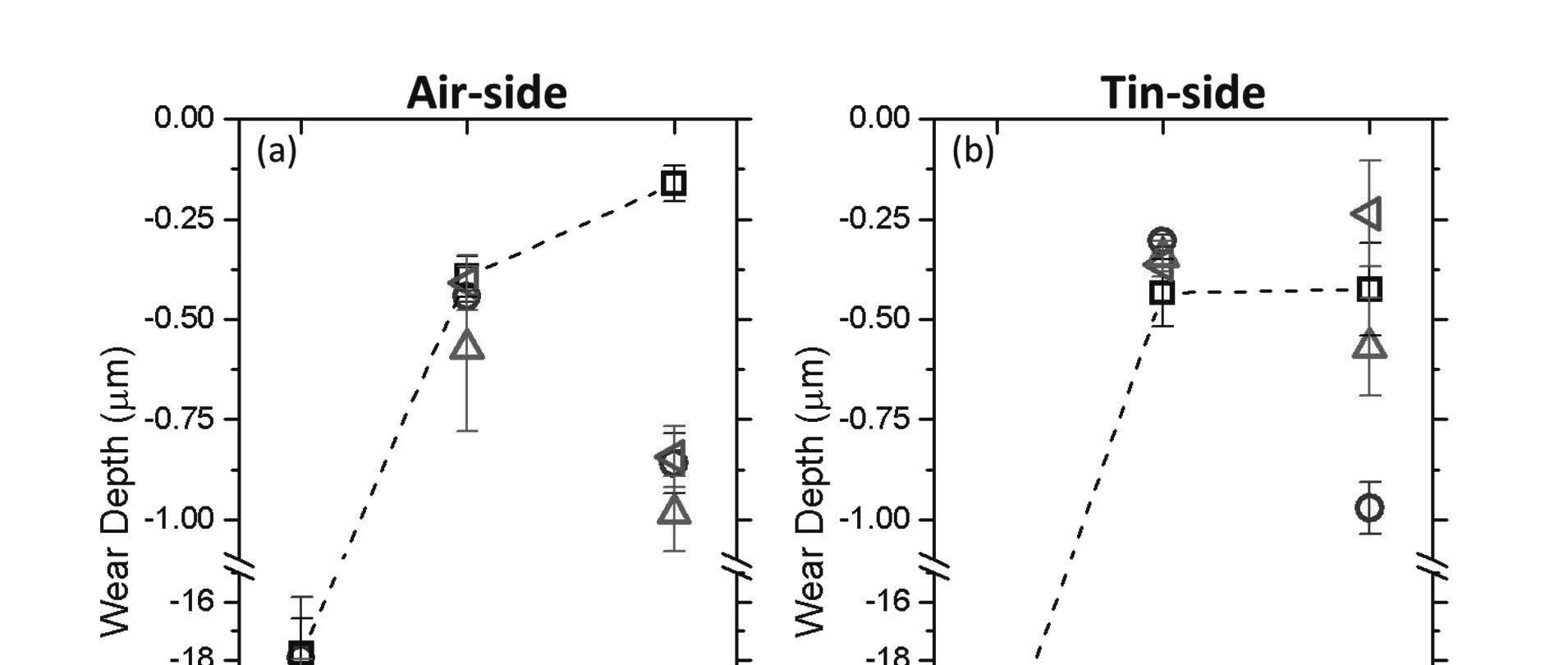
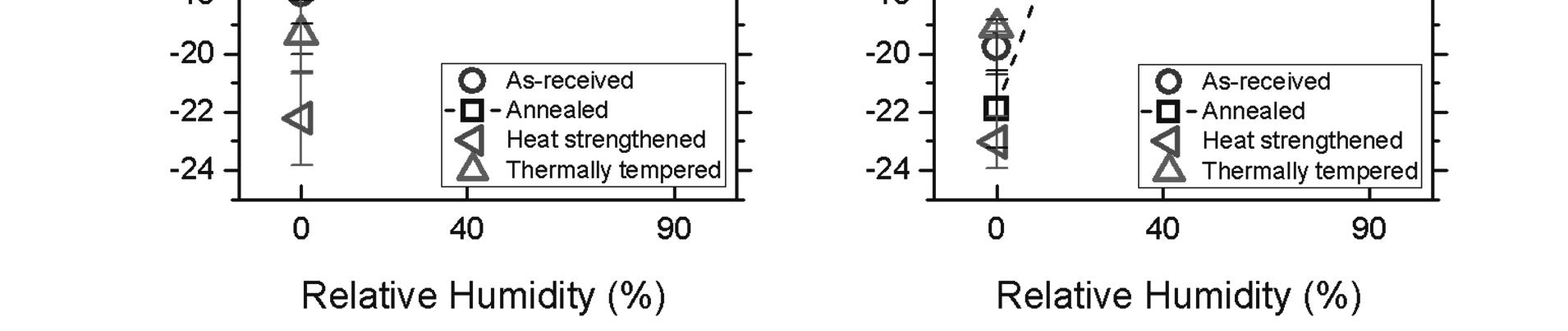
While heat strengthened and thermally tempered glasses had high indentation fracture resistance, both treatments resulted in poor wear-resistance at 90% RH. Figure 2 summarizes the wear behavior for air-side and tin-side SLS float glass as a function of relative humidity and thermal treatment. In dry environments, moderate wear conditions resulted in mechanical abrasion of the soda lime float glass surface regardless of treatment or air/tin side. At 40% RH, the wear depth decreased by 50-70 times compared to wear depth at 0% RH and wear debris adhered onto
the borosilicate counter-surface. The side of the float glass did not appear to influence wear outcomes.
Figure 2. The wear depth of soda lime float glass as a function of humidity for the air-side (a) and the tin-side (b). Four thermal processing conditions were compared: as-received (○), annealed (□), heat strengthened ( ), thermally tempered (∆). The dashed lines are drawn by connecting the annealed surface data as a guide to the eye. The error bars represent standard error.
At 90% relative humidity (RH) conditions, significant differences in wear behavior between thermal treatments and air/tin sides of the float glass were observed. The air-side annealed soda lime float glass showed greater wear resistance compared to the tin-side. Thermally tempered soda lime glasses, regardless of the side of the float glass side, became more damaged at the same wear test condition. It is interesting to note that for the tin-side, the heat strengthened and thermal tempered surfaces showed larger variances in wear depth. In these cases, it is speculated that the initial wear debris generated influenced the wear behavior outcomes. Interestingly, the borosilicate ball counter-surface was polished flat regardless of the substrate type, suggesting that the wear debris generated was pushed out from the system. Statistically significant interactions between humidity, float glass side (air vs. tin), and thermal treatments were observed at high humidity. These results cast doubt on the hypothesis that highly mobile sodium ions are the main determinant for high wear resistance under moderate wear conditions govern by shear force.[1] Sodium has greater leachability in soda lime glasses with higher fictive temperatures due to the larger free volume.[17] Since heat strengthened and thermally tempered glasses have a higher fictive temperature, sodium modifiers should have a greater leachability. If the mobility of sodium modifiers played a critical role for high wear resistance under moderate wear conditions at 90% RH, then it would have been anticipated that heat strengthened and thermally tempered glasses have higher wear resistance. Yet, the opposite is observed—annealed glasses have the highest wear resistance while heat strengthened and thermally tempered are susceptible to shear-induced
80th Conference on Glass Problems 18
damage.[1] Annealing allows for structural relaxation of the silicate network allowing for a narrower bond parameter distribution while glasses with higher fictive temperatures will have a broader bond parameter distribution.[18]
It can then be hypothesized that strained Si-O bonds are more susceptible to shear-induced hydrolysis resulting in greater damage under moderate wear conditions at high humidity.[1,14] While residual stress may influence wear behavior, no correlation was observed between the magnitude of residual stress and wear behavior at 90% RH.[1] Nevertheless, it may be difficult to separate the impact of residual stress and strained silicate network since residual stress generated by thermal treatments is dependent on strained Si-O bonds.
These findings then suggest that in addition to glass composition, processing conditions of the soda lime glass also affect the wear behavior. Furthermore, it also demonstrates that strengthening strategies, such as thermal tempering, do not necessarily demonstrate high wear resistance since mechanical behavior under one loading condition is not predictive of the material’s response under another loading condition.[10] Like most mechanical testing, wear testing requires a large sample size for a statistically significant conclusion.
WEAR BEHAVIOR OF SODA LIME GLASSES UNDER SEVERE WEAR CONDITIONS
Like moderate wear, severe wear behavior also depends on glass composition and material processing conditions. The large normal load applied under severe wear conditions generates lateral cracks that can propagate to the surface or intersect with other sub-surface cracks resulting in chipping. Chipping due to severe wear increases the width of the wear track and volume of removed material. In contrast, the width of the wear track under moderate wear conditions does not appear to be influenced by the thermal processing treatment. This indicates that under moderate wear conditions, lateral cracks were either not initiated, do not propagate to the surface or do not intersect with possible sub-surface cracking.
In the presence of water, it was found that thermally tempered glass was more susceptible to time-delayed chipping along the wear track as compared to annealed glass. Over time, chipping widens the damaged region by 10 times making the scratch on tempered glass more visible.[2] In comparison, annealed glasses experience minimal crack growth over time even in the presence of water.[2]
While lateral cracks are generated in both annealed and thermally tempered glass, the lateral crack propagation to the surface (resulting in chipping) appears to differ. This may be due to sub-critical crack growth (SCCG) which is a mechanochemical event involving chemicallyassisted crack propagation under applied stresses.[19,20] Commonly referred to as stress corrosion, SCCG depends on water transport to the flaw site and subsequent hydrolysis of the silicate network. The transport of water and hydroxylation kinetics depend strongly on the network structure. [21–23] Higher fictive temperature glasses, or glasses with more open structures, have faster water transport through the glass surface.[17] It can then be hypothesized that thermally tempered glass, or glasses that have high fictive temperatures and more open network structures, are more susceptible to time-dependent chipping along the wear track in the presence of molecular water.
PATH FORWARD
A vast majority of literature on the mechanical behavior of glasses focuses on mechanical strength, crack propagation and indentation hardness. Yet, shear-induced damage, such as scratching, is a poorly understood failure mode that has critical implications for glass products. 80th
Scratches and wear can act as stress concentrators, ultimately compromising the mechanical strength of the glass. It is critical to understand that mechanical behavior under a given loading condition (e.g. indentation along the surface normal direction) does not necessarily predict the mechanical behavior under another loading condition (i.e., interfacial shear stress).
While compositional and processing strategies have been developed to create stronger soda lime glass products, these solutions may not provide higher resistance to damage under shear stress. For example, while thermally and chemically tempered float glass has higher fracture strength due to the compressive stress casing, they are highly susceptible to both moderate and severe wear conditions. Wear behavior is complex and appears to depend on the interaction of multiple variables including substrate composition, counter-surface composition, silicate network structure, environmental conditions, and material processing. More work needs to be done to identify material and environmental parameters that govern wear, understand the contribution and interaction of these variables, and gain a mechanistic understanding of wear, especially in humid environments. Eventually, this will bring us closer to damage-resistant glass.
ACKNOWLEDGEMENTS. This work was supported by the National Science Foundation (Grant No. DMR-1609107) and the Usable Glass Strength Consortium (UGSC). During this study, NS was supported by the NSF Graduate Research Fellowship Program (Grant No. 1255832).
REFERENCES
[1] N. Sheth, A. Howzen, A. Campbell, S. Spengler, H. Liu, C.G. Pantano, S.H. Kim, Effects of tempering and heat strengthening on hardness, indentation fracture resistance, and wear of soda lime float glass, Int. J. Appl. Glas. Sci. (2019) ijag.13507. doi:10.1111/ijag.13507.
[2] J. Schneider, S. Schula, W.P. Weinhold, Characterisation of the scratch resistance of annealed and tempered architectural glass, Thin Solid Films. 520 (2012) 4190–4198. doi:10.1016/j.tsf.2011.04.104.
[3] A. Alazizi, A.J. Barthel, N.D. Surdyka, J. Luo, S.H. Kim, Vapors in the ambient - A complication in tribological studies or an engineering solution of tribological problems?, Friction. 3 (2015) 85–114. doi:10.1007/s40544-015-0083-5.
[4] Z. Chen, X. He, C. Xiao, S. Kim, Effect of Humidity on Friction and Wear—A Critical Review, Lubricants. 6 (2018) 74. doi:10.3390/lubricants6030074.
[5] H. He, S.H. Kim, L. Qian, Effects of contact pressure, counter-surface and humidity on wear of soda-lime-silica glass at nanoscale, Tribol. Int. 94 (2016) 675–681. doi:10.1016/j.triboint.2015.10.027.
[6] P. Bandyopadhyay, A.K. Mukhopadhyay, Role of shear stress in scratch deformation of soda-lime-silica glass, J. Non. Cryst. Solids. 362 (2013) 101–113. doi:10.1016/j.jnoncrysol.2012.11.019.
[7] H. He, L. Qian, C.G. Pantano, S.H. Kim, Effects of humidity and counter-surface on tribochemical wear of soda-lime-silica glass, Wear. 342–343 (2015) 100–106. doi:10.1016/j.wear.2015.08.016.
[8] L.C. Bradley, Z.R. Dilworth, A.L. Barnette, E. Hsiao, A.J. Barthel, C.G. Pantano, S.H. Kim, Hydronium ions in soda-lime silicate glass surfaces, J. Am. Ceram. Soc. 96 (2013) 458–463. doi:10.1111/jace.12136.
[9] H. He, L. Qian, C.G. Pantano, S.H. Kim, Mechanochemical Wear of Soda Lime Silica Glass in Humid Environments, J. Am. Ceram. Soc. 97 (2014) 2061–2068. doi:10.1111/jace.13014.
80th Conference on Glass Problems
[10] N.D. Surdyka, C.G. Pantano, S.H. Kim, Environmental effects on initiation and propagation of surface defects on silicate glasses: scratch and fracture toughness study, Appl. Phys. A. 116 (2014) 519–528. doi:10.1007/s00339-014-8552-7.
[11] J. Luo, W. Grisales, M. Rabii, C.G. Pantano, S.H. Kim, Differences in surface failure modes of soda lime silica glass under normal indentation versus tangential shear: A comparative study on Na + /K + -ion exchange effects, J. Am. Ceram. Soc. 102 (2018) 1665–1676. doi:10.1111/jace.16019.
[12] H. He, J. Luo, L. Qian, C.G. Pantano, S.H. Kim, Thermal Poling of Soda-Lime Silica Glass with Nonblocking Electrodes - Part 2: Effects on Mechanical and Mechanochemical Properties, J. Am. Ceram. Soc. 99 (2016) 1231–1238. doi:10.1111/jace.14080.
[13] J. Luo, H. Huynh, C.G. Pantano, S.H. Kim, Hydrothermal reactions of soda lime silica glass – Revealing subsurface damage and alteration of mechanical properties and chemical structure of glass surfaces, J. Non. Cryst. Solids. 452 (2016) 93–101. doi:10.1016/j.jnoncrysol.2016.08.021.
[14] S.H. Hahn, H. Liu, S.H. Kim, A.C.T. Van Duin, Atomistic Understanding of Surface Wear Process of Sodium Silicate Glass in Dry versus Humid Environments, ACS Appl. Mater. Interfaces. Submitted (2019) am-2019-181968.
[15] J. Luo, H. He, N.J. Podraza, L. Qian, C.G. Pantano, S.H. Kim, Thermal Poling of SodaLime Silica Glass with Nonblocking Electrodes-Part 1: Effects of Sodium Ion Migration and Water Ingress on Glass Surface Structure, J. Am. Ceram. Soc. 99 (2016) 1221–1230. doi:10.1111/jace.14081.
[16] N. Sheth, D. Ngo, J. Banerjee, Y. Zhou, C.G. Pantano, S.H. Kim, Probing HydrogenBonding Interactions of Water Molecules Adsorbed on Silica, Sodium Calcium Silicate, and Calcium Aluminosilicate Glasses, J. Phys. Chem. C. 122 (2018) 17792–17801. doi:10.1021/acs.jpcc.8b04233.
[17] S. Amma, J. Luo, S.H. Kim, C.G. Pantano, Effects of fictive temperature on the leaching of soda lime silica glass surfaces, J. Am. Ceram. Soc. 100 (2017) 1424–1431. doi:10.1111/jace.14754.
[18] J. Luo, Y. Zhou, S.T. Milner, C.G. Pantano, S.H. Kim, Molecular dynamics study of correlations between IR peak position and bond parameters of silica and silicate glasses: Effects of temperature and stress, J. Am. Ceram. Soc. 101 (2018) 178–188. doi:10.1111/jace.15187.
[19] R. Danzer, T. Lube, P. Supancic, R. Damani, Fracture of ceramics, Adv. Eng. Mater. 10 (2008) 275–298. doi:10.1002/adem.200700347.
[20] M. Ciccotti, Stress-corrosion mechanisms in silicate glasses, J. Phys. D. Appl. Phys. 42 (2009). doi:10.1088/0022-3727/42/21/214006.
[21] J. Yeon, A.C.T. van Duin, ReaxFF Molecular Dynamics Simulations of Hydroxylation Kinetics for Amorphous and Nano-Silica Structure, and Its Relations with Atomic Strain Energy, J. Phys. Chem. C. 120 (2016) 305–317. doi:10.1021/acs.jpcc.5b09784.
[22] E.A. Leed, C.G. Pantano, Computer modeling of water adsorption on silica and silicate glass fracture surfaces, J. Non. Cryst. Solids. 325 (2003) 48–60. doi:10.1016/S00223093(03)00361-2.
[23] E.A. Leed, J.O. Sofo, C.G. Pantano, Electronic structure calculations of physisorption and chemisorption on oxide glass surfaces, Phys. Rev. B - Condens. Matter Mater. Phys. 72 (2005) 1–11. doi:10.1103/PhysRevB.72.155427.