Applications and Metrology at Nanometer Scale 2: Measurement Systems, Quantum Engineering and RBDO Method, Volume 10 Pierre Richard Dahoo
Visit to download the full and correct content document: https://ebookmass.com/product/applications-and-metrology-at-nanometer-scale-2-me asurement-systems-quantum-engineering-and-rbdo-method-volume-10-pierre-richard -dahoo/

More products digital (pdf, epub, mobi) instant download maybe you interests ...

Metrology and Instrumentation: Practical Applications for Engineering and Manufacturing (Wiley-ASME Press Series) 1st Edition Samir Mekid
https://ebookmass.com/product/metrology-and-instrumentationpractical-applications-for-engineering-and-manufacturing-wileyasme-press-series-1st-edition-samir-mekid/

Foundation Engineering: Geotechnical Principles and Practical Applications 1st Edition Richard Handy
https://ebookmass.com/product/foundation-engineeringgeotechnical-principles-and-practical-applications-1st-editionrichard-handy/

Atomic and Nano Scale Materials for Advanced Energy Conversion, Volume 2 Zongyou Yin
https://ebookmass.com/product/atomic-and-nano-scale-materialsfor-advanced-energy-conversion-volume-2-zongyou-yin/

Smart Materials in Additive Manufacturing, Volume 2: 4D Printing Mechanics, Modeling, and Advanced Engineering Applications Mahdi Bodaghi
https://ebookmass.com/product/smart-materials-in-additivemanufacturing-volume-2-4d-printing-mechanics-modeling-andadvanced-engineering-applications-mahdi-bodaghi/

Reservoir Characterization: Fundamentals and Applications. Volume
2 Fred Aminzadeh
https://ebookmass.com/product/reservoir-characterizationfundamentals-and-applications-volume-2-fred-aminzadeh/

Practical Debugging at Scale Shai Almog
https://ebookmass.com/product/practical-debugging-at-scale-shaialmog/

Fetal and Neonatal Physiology, 2-Volume Set 6th Edition
Richard A. Polin
https://ebookmass.com/product/fetal-and-neonatalphysiology-2-volume-set-6th-edition-richard-a-polin/
Quantum Materials, Devices, and Applications Mohamed Henini
https://ebookmass.com/product/quantum-materials-devices-andapplications-mohamed-henini/

Quantum Mechanics 3rd Edition Nouredine Zettili
https://ebookmass.com/product/quantum-mechanics-3rd-editionnouredine-zettili/

Applications and Metrology at Nanometer Scale 2
Reliability
Systems
Measurement Systems, Quantum Engineering and RBDO Method
First published 2021 in Great Britain and the United States by ISTE Ltd and John Wiley & Sons, Inc.
Apart from any fair dealing for the purposes of research or private study, or criticism or review, as permitted under the Copyright, Designs and Patents Act 1988, this publication may only be reproduced, stored or transmitted, in any form or by any means, with the prior permission in writing of the publishers, or in the case of reprographic reproduction in accordance with the terms and licenses issued by the CLA. Enquiries concerning reproduction outside these terms should be sent to the publishers at the undermentioned address:
ISTE Ltd
John Wiley & Sons, Inc.
27-37 St George’s Road 111 River Street London SW19 4EU Hoboken, NJ 07030
UK USA
www.iste.co.uk
www.wiley.com
© ISTE Ltd 2021
The rights of Pierre-Richard Dahoo, Philippe Pougnet and Abdelkhalak El Hami to be identified as the authors of this work have been asserted by them in accordance with the Copyright, Designs and Patents Act 1988.
Library of Congress Control Number: 2020950471
British Library Cataloguing-in-Publication Data
A CIP record for this book is available from the British Library
ISBN 978-1-78630-687-6
1.4.1.
1.5.1.
Chapter 2.
2.3. The density matrix for a two-level laser system
2.3.1. Definition of the density matrix
2.3.2. Density matrix properties
2.3.3. Equation of motion of the density matrix
2.3.4. Application to a two-level system
2.4. Ising’s phenomenological model for cooperative effects
2.4.1. The Ising 1D model
Chapter 3. Quantum Optics and Quantum Computers
3.1. Introduction
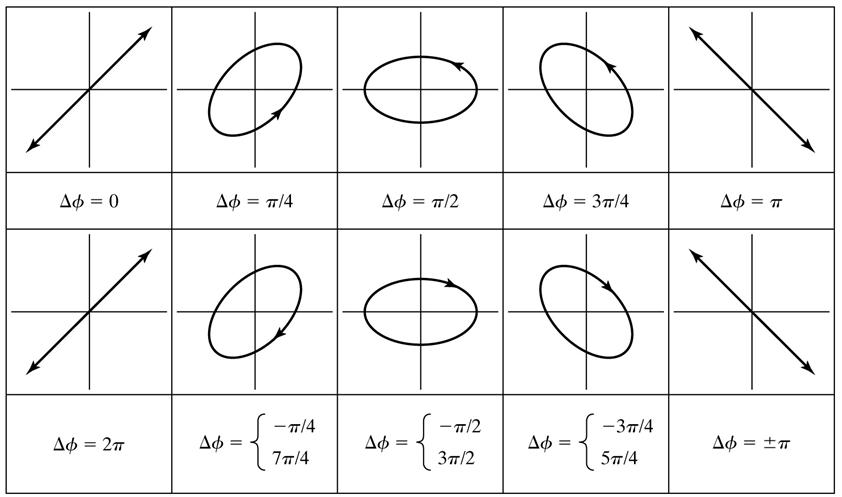
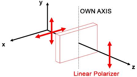
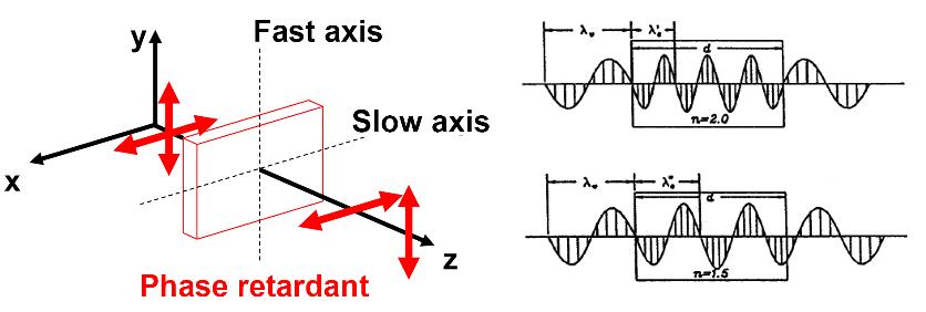
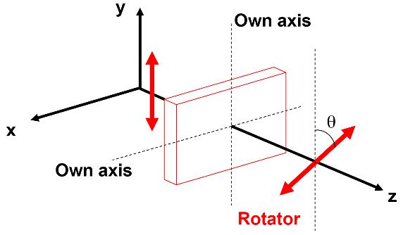
3.2. Polarized light in quantum mechanics
3.3. Introduction to quantum
3.4. Preparing a qubit .................................
3.4.1. Application of the Bloch sphere
3.5. Application: interaction of a qubit with a classical field
3.5.1.
3.5.2.
3.6. Applying Ramsey fringes to evaluate the duration of phase coherence
3.6.1.
3.6.2.
Chapter 4.
4.1.
4.4. Reliability-based
4.4.1.
4.4.2.
4.4.3.
4.4.4.
4.4.5.
4.4.6.
4.5.
4.5.1.
4.5.2.
4.5.3. Application:
4.5.4.
4.6. Reliability-based design optimization in nanotechnology
4.6.1. Thin-film SWCNT structures
4.6.2. Digital model of thin-film SWCNT structures .............
4.6.3. Numerical results ..............................
Preface
At the nanoscale, properties of matter cannot be explained by the laws of classical physics. To build models capable of interpreting the properties of matter on this scale, it is necessary to rely on the principles of quantum mechanics. The radical concepts of quantum mechanics and the development of nanotechnologies have contributed to the emergence of quantum engineering and a quantum information science.
Quantum engineering includes very sensitive materials and sensors that open up new fields of application, nanometer-sensitive measurement systems based on photonics and communication systems that perform well in terms of security. Quantum computing includes quantum computers and the development of new algorithms. Quantum computers are made up of quantum systems with two energy levels that follow the same laws of behavior as atoms or electrons enabling, with the development of quantum computing algorithms, performance that cannot be achieved with classical computers. Quantum technologies, nanotechnologies and nanoscience are identified as the sources of disruptive innovations that will bring technologies considered essential in the 21st Century.
The purpose of Applications and Metrology at Nanometer Scale, a book in two volumes, is to provide essential knowledge that will lead to the industrial applications of quantum engineering and nanotechnologies. The authors, through their skills and experience, combine their know-how in fundamental physics, engineering sciences and industrial activities. As with Volume 1, Applications and Metrology at Nanometer Scale 2 is designed to provide applications for Nanometer-scale Defect Detection Using Polarized Light (Reliability of Multiphysical Systems Set Volume 2). It describes
experimental and theoretical methods implemented in the framework of fundamental research to better understand physical–chemical processes at the nanoscale, presents examples of optical techniques based on the polarized light, allowing measurements to be made at the nanoscale, and illustrates the theoretical approaches with numerous applications.
This book is intended for master’s and PhD students, engineering students, professors and researchers in materials science and experimental studies, as well as for industrialists of large groups and SMEs in the electronics, IT, mechatronics, or optical or electronic materials fields.
Chapter 1 deals with optical systems that enable measurements to be made on a nanoscale: the Fabry–Pérot cavity, homodyne interferometry, heterodyne interferometry, the optical lambda meter and ellipsometry with a rotating analyzer. The emphasis is on applications through exercises or analysis of study results on the use of interference techniques to study matter and materials.
Chapter 2 presents models of quantum physics that describe how a quantum two-energy level system interacts with its environment. As a free particle such as the electron that interacts with an external magnetic field with its spin, the derivation of the concept of spin from the Dirac equation is explained, which is the subject of an application exercise. The concept of density matrix (definition, propagation, equation of motion) is then presented and applied to a laser system with two energy levels and to a set of atoms interacting with the oscillating electric field of an electromagnetic wave. Finally, the Ising phenomenological model is presented, which is the subject of an application exercise.
Chapter 3 aims to provide theoretical foundations and examples of applications to understand the functioning of a quantum gate. A reminder is given on the modeling of light in quantum mechanics and on the representation by the Bloch sphere of the states of a two-level quantum system. The functioning of a quantum computer is introduced. Examples of applications show how to use the Bloch sphere, predict the evolution of an initial state of the system and obtain, by coupling, the oscillations of the Rabi population. Another application studies the coupling of an atom with light radiation and the effect on Rabi oscillations of a disagreement between the frequency of the atom and the frequency of the radiation. A final exercise
deals with obtaining Ramsey fringes and their application to the functioning of a quantum gate.
Chapter 4 presents a reliability-based design optimization (RBDO) method of mechanical structures. This method guarantees a balance between the cost of defining the system and the assurance of its performance under the planned conditions of use. It is based on taking into account uncertainties and on the simultaneous resolution of two issues: optimizing the cost of producing structures performing the expected functions while ensuring a sufficient probability of operation under conditions of use (reliability). The RBDO method is applied to the optimization of the parameters of several mechanical components and of a printed circuit of an electronic board, and to ensure the reliability of the estimate of the measurement of the mechanical properties of carbon nanotube structures (Young’s modulus of elasticity).
Pierre Richard DAHOO
Philippe POUGNET
Abdelkhalak EL HAMI
November 2020
Introduction
The scientific study of measurement is known as metrology. Any measure is based on a universally accepted standard and any measuring process is prone to uncertainty. In engineering science, measurement concerns various types of parameters. Legal metrology is imposed by a regulatory framework that the manufactured product must respect. Technical or scientific metrology involves the methods used to measure the technical characteristics of the manufactured product. In engineering sciences, measurement concerns various types of parameters. In a more general context of a systemic approach, metrology should also be considered in connection with other indicators of the production system. These measures enable the follow-up and development of the processes implemented for ensuring and optimizing product quality or reducing failure so that it meets client expectations. The ability of a product to meet quality and reliability expectations can be addressed in the design stage, according to a RBDO (Reliability-Based Design Optimization) approach described in Volume 2 of the Reliability of Multiphysical Systems Set, entitled Nanometer-scale Defect Detection Using Polarized Light. More generally, RBDO makes it possible to consider the uncertain parameters of manufacturing processes, measurement and operational conditions in order to optimize the manufacturing process, the design parameters and the overall quality of the product.
Nanometer-scale Defect Detection Using Polarized Light focused on three levels of design for manufacturing an industrial product:
– Numerical methods developed in engineering from mathematical models and theories in order to optimize product quality from its design
according to RBDO. This methodology is a source of applications in engineering science intended to address optimization problems in the industrial field.
– Experimental methods developed in fundamental research relying on the light–matter interaction and on simulation-based analysis using theoretical models in order to make nanometer-scale measurements and conduct the analysis. These methods are used in nanosciences for the elaboration of knowledge leading to nanotechnologies.
– Finally, the application of these two approaches in the example presented in Chapter 9 of Nanometer-scale Defect Detection Using Polarized Light to the measurement of the physical properties of a nanomaterial, carbon nanotube.
In sciences, there are various ways to measure a dimension. The measuring instruments or methods employed depend on the scale at which metrology is approached. In order to describe the issues at stake for measurement at a given scale, we present the methods employed for the measurement processes at two scales of interest for scientists, namely the infinitely small, which corresponds to the Planck length of 1.6 x 10⁻³⁵ m, and the infinitely large, which corresponds to the diameter of the Universe evaluated at 8.8 x 1026 m. This is to help the reader understand that, even though becoming an expert in a scientific field or in a given subject is not the objective, it is necessary to understand some basic tenets in order to master the methods used for successful metrology at a given scale.
In 1899, Planck determined a unit of length lP=(Gh/2c3) 1.6 x 10⁻³⁵ m, referred to as Planck length, based on fundamental constants: G, gravitational constant (6.6 x 10⁻¹¹ Nm2 Kg–2), h, Planck’s constant (6.64 x 10⁻³⁴ Js) and c, the speed of light (2.99,729,458 x 108 ms–1). This length cannot be measured with the measurement technologies available on Earth. Indeed, the smallest length measurable at the LHC (Large Hadron Collider) of CERN, the particle accelerator in which two protons are made to frontally collide in a ring of 26,659 km, which led to the discovery in 2012 of the Higgs boson, is approximately 10–16 m, which is 19 orders of magnitude higher than the Planck length. CMS and ATLAS detectors were used in the observation of the Higgs boson, the latest prediction of the standard model not yet observed. The measurement at the scale of 10–16 m is made by compressing energy to reach an infinitely small spatial volume.
The principle of measurement at the scale of fundamental particles is mainly based on three relations: the de Broglie relation between the momentum p and the wavelength , p=h/, which introduces the wave–particle duality for matter; the relation that links the energy E of a particle to its wave frequency or wavelength , such as proposed by Einstein to explain the photoelectric effect E = hc/; and the relation that links the energy E of a particle of rest mass m to its rest mass energy and to its kinetic energy associated with its momentum p=mv, E2= m 2 c 4 + p2c2, as mentioned in Einstein’s special theory of relativity. In the above formulas, v is the speed of the particle of mass m and c is the speed of light. The energy E can also be expressed by the formula E= γmc2, where γ is given by γ =1/(1-v2/c2). The speed of a particle is therefore given by v/c=(1-(mc2/E)2.
In the LHC, the energy of a proton is 7 TeV (1.2 10–6 J), far higher (by a factor of 7,500) than its rest energy, mc2, which is 938 MeV. The formula for speed can then be rewritten as v/c = (1-(m 2 c4/2E2)), which is equal to 1 to the nearest 10–8. Using the relation E= hc/, the resulting value of the wavelength is of the order of 10–16 m, which gives the dimensions that can be reached in the LHC. The mass measured during two experiments at CERN in the LHC (8 TeV in 2012 and 13 TeV in 2015) is confirmed to the value of 125 GeV.
To detect the Higgs boson, a particle of mass 125 GeV associated with the Higgs field, while the mass of a proton is 938 MeV, the proton is accelerated and consequently its kinetic energy is increased so that its energy given by E= γmc 2 significantly exceeds 938 MeV (8 TeV in 2012 and 13 TeV in 2015). The disintegration of colliding protons, each contributing an energy load of 8 TeV or 13 TeV, releases sufficient energy so that the Higgs boson can be expected to emerge during the recombination of subatomic particles. As the Higgs boson decays quasi-instantaneously after its emergence, the products of its decay must be analyzed to identify the excess energy and therefore the excess mass about 125 GeV.
It is worth noting that at the Planck length, the required energies that cannot be expected in a particle accelerator would lead to the emergence of black holes.
The opposite dimensional extreme towards the infinitely large corresponds to the spatial extent of the Universe, whose estimated value according to cosmologists is 1026 m. In cosmology, the observable Universe is a term used to describe the visible part of our Universe, the point from which light reaches us. It is a sphere whose limit is located at the cosmological horizon, having the Earth at its center. It is therefore a relative notion, as for other observers located somewhere else in the Universe, the observable sphere would not be the same (while its radius would be identical).
In cosmology, distances are measured in light-years. A light-year is the distance that light travels in one year, which corresponds to approximately 9.5 x 10¹² m. The megaparsec, which is 3.26 million (3.26 x 10⁶) light-years, is another unit of distance that is also specific to extragalactic astrophysics. Finding the size of the Universe involves accurate measurements of fossil radiation, or of the cosmic microwave background (CMB) radiation that originated in the Big Bang and can be used to determine the volume filled by the Universe since its creation. Predicted for the first time by Ralph Alpher in 1948 in his thesis work, CMB was discovered by Arno Penzias and Robert Wilson at “Bell Telephone Laboratories” during the development of a new radio receiver following the interferences detected independently of the orientation of the antenna they were building. While in a first approximation CMB is isotropic, accurate measurements of this radiation lead to determining H0, the Hubble constant, which indicates the rate of expansion of the Universe.
In cosmology, detectors are above-ground telescopes. The WMAP (Wilkinson Microwave Anisotropy Probe) satellite launched in 2001 enabled the detection of CMB with good accuracy. Its intensity varies slightly in different directions of the sky and the fluctuations can be determined. Extremely accurate measurements of the WMAP in 2003 made it possible to calculate a value of H0 of 70 kilometers per second and per megaparsec, which is within 5% in the hypothesis of a constant rate of expansion. Since the Universe is accelerating, during its expansion, the correction brought to H0 made it possible to estimate the age of the Universe to 13.75 billion years, with a 0.1 billion margin of error. It is the scale fitting the domain to which corresponds the age of the Universe deduced from observations related to the Big Bang based on the inflationary model in an expanding Universe.
After the Big Bang, the elementary subatomic particles had no mass and could travel at the speed of light. After the expansion of the Universe and its cooling, the particles interacted with the Higgs field and consequently gained a mass.
In the history of the Universe, the elementary particles interacted with the Higgs field, 10–12 s after the Big Bang. The value of 125 GeV is considered as the critical value between a stable universe and a metastable universe. The “standard model of cosmology” elaborated at the beginning of this century, towards 2000, is probably at present the best model that enables the description of the evolution of the Universe, the significant stages in the history of the observable Universe as well as its current content, as revealed by astronomical observations. The standard model describes the Universe as an expanding homogeneous and isotropic space, on which large structures are overlaid as a result of the gravitational collapse of primordial inhomogeneities, which were formed during the inflation phase. There are still questions to be addressed, such as the nature of certain constituents of the Universe, black matter, and black energy and their relative abundance.
The inflationary model relies on the hypothesis of the Universe expanding with an exponential acceleration R(t)=R0exp(H(t)t), 10–30 s after the Big Bang, where H(t) is the Hubble constant. This constant is measured from the Doppler effect, which explains the red shift of the light radiation emitted by a distant star that is receding from the point of observation. The inflationary model allows for a plausible interpretation of the CMB isotropy, with relative variations of the measured temperature of 10–5. Based on the data provided by the Hubble, COBE (Cosmic Background Explorer) and WMAP (Wilkinson Microwave Anisotropy Probe) telescopes, as well as by the BOOMerang (Balloon Observations Of Millimetric Extragalactic Radiation ANd Geophysics) and MAXIMA (Millimeter Anisotropy eXperiment IMaging Array) experiments, scientists were able to determine the age of the Universe is 13.75 billion light-years.
The Universe is presently in accelerated expansion: if its speed is 70 km/s at 1 Megaparsec, it doubles at 2 Megaparsec, reaching 140 km/s and so on. Considering the Doppler shift or the red shift for the receding stars, and therefore the fact that not only are the stars receding, but also those that are twice farther recede twice faster, therefore considering the metrics applicable to the space that is stretching while galaxies are receding, the 13.8 billion years between the beginning of the rapid expansion of the Universe 10–30 s
after the Big Bang amount to 46.5 billion light-years, which is a radius of 93 billion light-years. Obviously, the light of stars that are at the periphery or at the cosmological horizon can no longer reach us, but as what we observe today goes back to the time needed for light to reach us while traveling a distance in a stretching space.
These two examples show that at each dimensional scale, besides the appropriate experimental measurement techniques required for observation, we must have a good mastery of the theories adapted for the interpretation and analysis of the gathered data. At each scale, the engineer must acquire specific knowledge elaborated in the laboratories and develop the competences to enable the mastery of technologies and the implementation of innovations.
This book which provides applications for Volume 2 of the Reliability of Multiphysical Systems Set (Nanometer-scale Defect Detection Using Polarized Light), focuses on knowledge elaborated at the nanometer scale for applications in the field of engineering sciences. The subjects approached are related to simulation experiments and engineering of nanometer-scale systems. The light–matter interaction has a special place among the subjects addressed, because the analysis of the properties and characteristics of matter is most often possible due to light being used as a probe. Similarly, simulation according to theoretical models based on quantum mechanics principles requiring field theory is also given particular attention.
Nanotechnologies and nanosciences are identified as sources of breakthrough innovations that will lead to the development of technologies that are considered primordial in the 21st Century. They should be deployed in eco-innovations and will increasingly become pervasive in the societal applications in various sectors. Without pretending to provide an exhaustive list, several examples are worth being mentioned: new energies and their recovery and storage, water purification, new materials that are lighter and more resilient for land and space transportation, construction and buildings, information technologies with quantum computers, embedded electronic systems and factory 4.0. The trend according to which states throughout the world offer financial support for the development of long-term projects in this field dates back to the beginning of the 21st Century. This is a reflection of the economic growth potential in nanotechnologies.
Similar to the inflationary model proposed by cosmologists to explain the countless galaxies and planetary systems, suns and black holes that constitute them, there was also a sharp increase in the volume of activities in nanosciences. The subjects approached in this book and in Volume 2 of the Reliability of Multiphysical Systems Set (Nanometer-scale Defect Detection Using Polarized Light) concern the field of engineers working in mechatronics, robotics and computation in modeling and simulation, for the societal spin-offs of nanotechnologies in the fields of land and space transportation, handicap, information and simulation technologies in a systemic approach. The level of knowledge acquired by the engineer should make innovation in nanotechnologies possible.
The contents of Nanometer-scale Defect Detection Using Polarized Light and Applications and Metrology at Nanometer Scale 1 & 2, jointly written by three authors, aim to develop knowledge that is essential at the nanometer scale, enabling trainee-engineers or engineers to develop nanotechnologybased devices or systems. To promote the deployment of nanotechnologies, the authors of these three books whose joint competences and experiences associate know-how in fundamental physics, engineering sciences and industrial activities cover a wide spectrum of application domains. Nanometer-scale Defect Detection Using Polarized Light builds a theoretical and experimental basis for understanding nanometer-scale metrology. This book in two volumes, Applications and Metrology at Nanometer Scale, enriches this theoretical basis with applications in the form of corrected exercises.