Metal-organic frameworks with heterogeneous structures ali morsali download pdf
Metal-Organic Frameworks with Heterogeneous Structures Ali Morsali
Visit to download the full and correct content document: https://ebookmass.com/product/metal-organic-frameworks-with-heterogeneous-struct ures-ali-morsali/
More products digital (pdf, epub, mobi) instant download maybe you interests ...
Metal-Organic Frameworks (MOFs) for Environmental Applications Sujit K. Ghosh
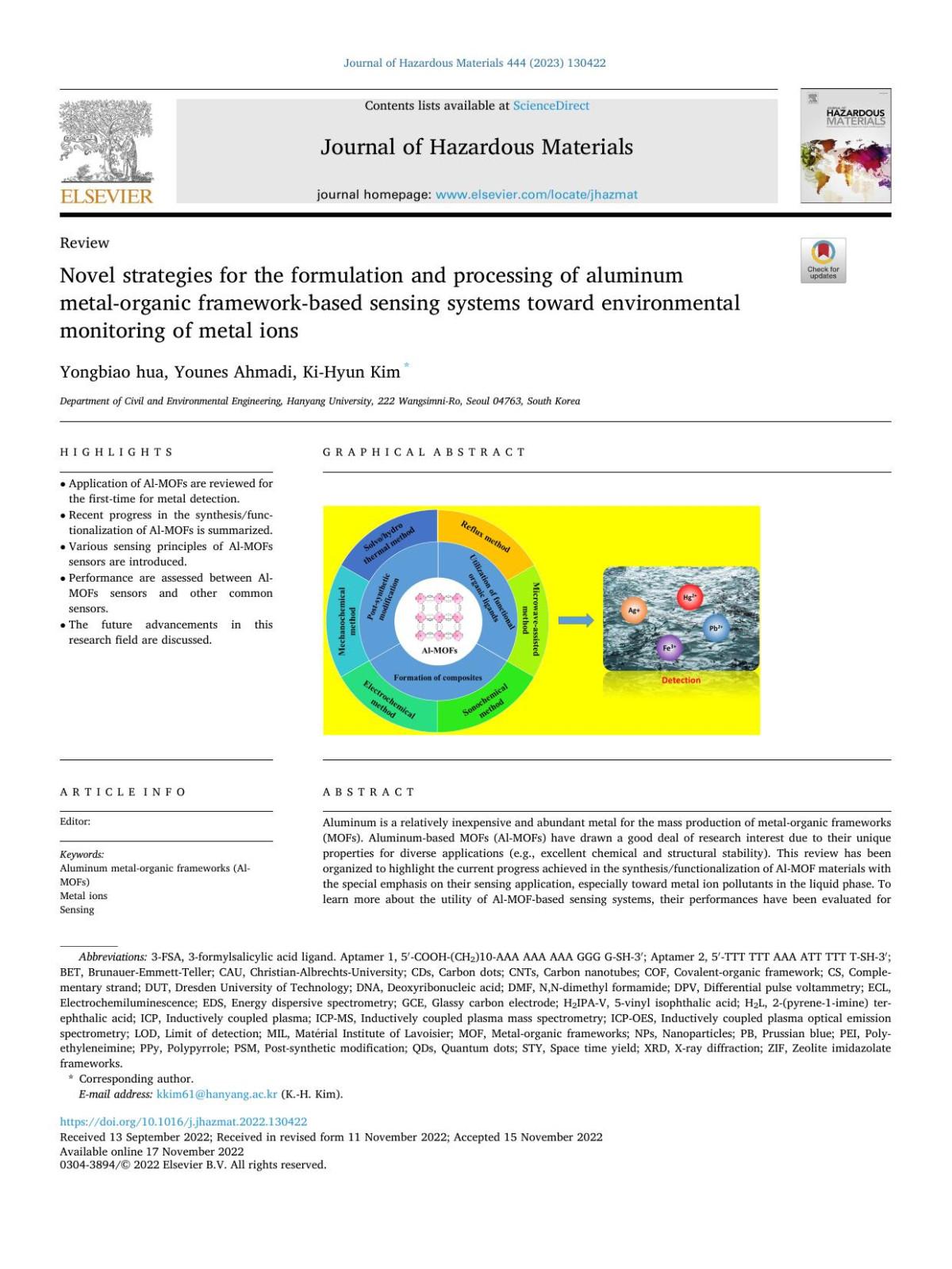
Novel strategies for the formulation and processing of aluminum metal-organic framework-based sensing systems toward environmental monitoring of metal ions Yongbiao Hua
For more information about Scrivener publications please visit www.scrivenerpublishing.com.
All rights reserved. No part of this publication may be reproduced, stored in a retrieval system, or transmitted, in any form or by any means, electronic, mechanical, photocopying, recording, or otherwise, except as permitted by law. Advice on how to obtain permission to reuse material from this title is available at http://www.wiley.com/go/permissions.
Wiley Global Headquarters
111 River Street, Hoboken, NJ 07030, USA
For details of our global editorial offices, customer services, and more information about Wiley products visit us at www.wiley.com.
Limit of Liability/Disclaimer of Warranty
While the publisher and authors have used their best efforts in preparing this work, they make no representations or warranties with respect to the accuracy or completeness of the contents of this work and specifically disclaim all warranties, including without limitation any implied warranties of merchantability or fitness for a particular purpose. No warranty may be created or extended by sales representatives, written sales materials, or promotional statements for this work. The fact that an organization, website, or product is referred to in this work as a citation and/or potential source of further information does not mean that the publisher and authors endorse the information or services the organization, website, or product may provide or recommendations it may make. This work is sold with the understanding that the publisher is not engaged in rendering professional services. The advice and strategies contained herein may not be suitable for your situation. You should consult with a specialist where appropriate. Neither the publisher nor authors shall be liable for any loss of profit or any other commercial damages, including but not limited to special, incidental, consequential, or other damages. Further, readers should be aware that websites listed in this work may have changed or disappeared between when this work was written and when it is read.
Library of Congress Cataloging-in-Publication Data
ISBN 978-1-119-79204-8
Cover image: Pixabay.com
Cover design by Russell Richardson
Set in size of 12pt and Minion Pro by Manila Typesetting Company, Makati, Philippines
List of Illustrations
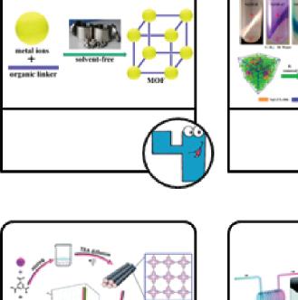
Figure 1.1 Simple description of 3D MOF chemistry. 2
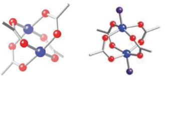
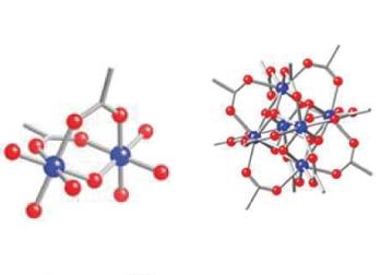
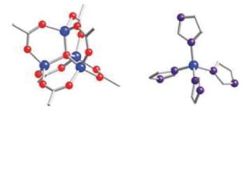
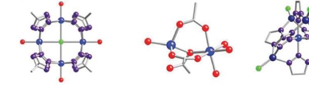
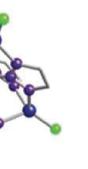
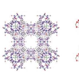
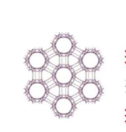
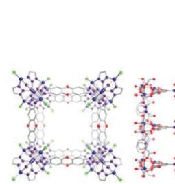
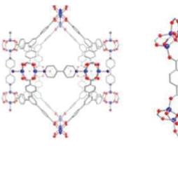
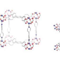
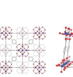
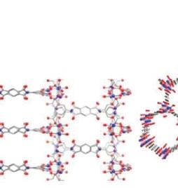
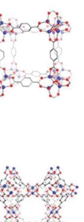
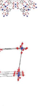
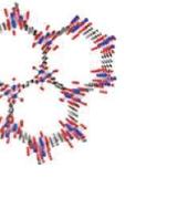
Figure 1.2 Some examples of metal nodes, organic linkers, and MOFs (definition of atom types: blue: metal; red: oxygen; purple: nitrogen; gray: carbon; and green: chlorine). 3
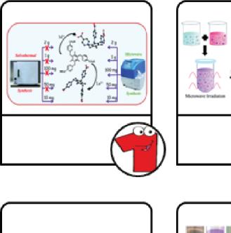
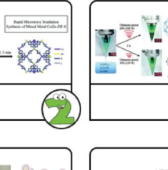
Figure 1.3 Some examples of MOFs synthesis methods. 7
Figure 2.1 Simple language to understand concept of complexity.
Figure 2.2 Overview of this book based on the effective factors in the construction MOFs with heterogeneous structures.
Figure 2.3 Classification of complexity key factors in MOFs (further details in text).
Figure 2.4 A cost-effective mixed-metal mixed-ligand MOF, which exhibits highly efficient photocatalytic H2 generation.
14
16
16
19
Figure 2.5 Defective linker concept for defect-engineered MOFs. 20
Figure 3.1 A photocatalyst MOF with three different ditopic linkers. 33
Figure 3.2 Structural analyses of a MOF-based photocatalyst with three different ditopic linkers. (a) Percent of BPDC-(HN2)2 incorporation in ReMOF-NH2 (X%). (b) PXRD patterns: Re-MOF, Re-MOF-NH2 (33%), Re-MOF-NH2 (80%) and Re-MOF simulated pattern. (c) SEM images: Re-MOF-NH2 (33%) and Re-MOF-NH2 (80%). (d) N2 adsorption isotherms: Re-MOF, Re-MOF-NH2 (33%) and Re-MOF-NH2 (80%).
viii List of Illustrations
(e) IR spectra: Re-MOF, Re-MOF-NH2 (33%) and Re-MOF-NH2 (80%).
Figure 3.3 (a) Copper-phosphonate CBU polyhedral. Octahedral Cu1 and square pyramidal Cu2: dark blue and light blue, respectively. PO3C tetrahedral: green. (b) The original structure of the considered isoreticular MOF.
Figure 3.4 Schematic representations of the happened processes in MOF with increased porosity. (a and b) Organic linker installation and linker labilization, respectively. (c) The produced hierarchically porous MOF through linker labilization (top). UV-vis analysis of linker exchange process. (a) Concentration of AZDC in supernatant as a function of incubation time in CBAB solutions with different concentrations. (b) Relationship between CBAB exchanged/ CBAB added, exchange ratio, and CBAB molarity. (c) PCN-160 crystals images with various exchange ratios.
Figure 3.5 Schematic representations of construction mechanism. (a) Formed micropores, (b and c) small and large mesopores, and (d) pores size distribution of the considered MOF (PCN-16034%) in the presence of acid in different amounts. (Top) (a) Representation of one kind of MOF in the presence of enzyme. (b) relative activity of the considered MOFs in the oxidative reaction of ABTS (2,2ʹ-azino-bis(3-ethylbenzothiazoline-6-sulphonic acid)) and o-PDA (o-phenylenediamine).
Figure 3.6 One kind of mixed-valence RuII/III MOF with mixed-linker.
Figure 3.7 Olefin hydrogenation mechanism.
Figure 3.8 Zeolite-like MOFs based on mixed linkers.
Figure 3.9 A mixed-ligand MOF with two ligands BTC (benzene-1,3,5-tricarboxylate) and BTRE (1,2-bis(1,2,4-triazol-4-yl)-ethane).
34
36
38
40
42
42
44
44
Figure 3.10 Stepwise preparation of {[Cu4(CDC)4(4,4ʹbipy)(H2O)2]3}n·xS. Copper: aqua; oxygen: red; nitrogen: blue; carbon; black. Hydrogen atoms have not been shown (top). Synthesis of the isostructural porphyrinic MOFs and obtained crystals photographs (bottom).
Figure 3.11 ADES-1: (a) coordination environment around Zn(II); (b) and (c) [Zn2(COO)2] SBU in 1D metal-carboxylate chain and double lined 2D network, respectively; (d) ABAB manner interlayer with lattice H2O.
Figure 3.12 ADES-2: (a) coordination environment around Cd(II); (b) and (c) [Cd2(COO)2] SBU in 1D metal-carboxylate chain and double lined 2D network, respectively; (d) Offset stacked 2D layers with the lattice H2O and π···π stacked L.
Figure 3.13 Direct synthesis mixed-ligands MOF film, RuBRuTB-UiO-67/TiO2/FTO through solvothermal method.
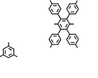
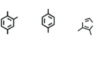
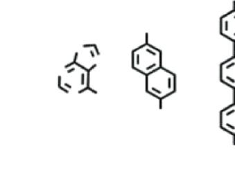
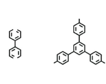
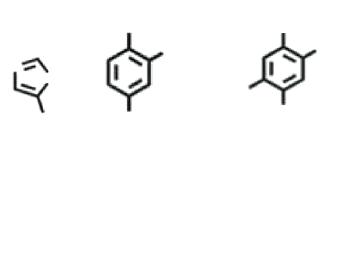
Figure 4.1 Some of the tritopic linkers.
Figure 4.2 The symmetry in organic linker. Tetratopic linkers with (a) symmetry C2h and (b) symmetry Cs.
Figure 4.3 Some of the tetratopic linkers.
Figure 4.4 A mixed-ligand MOF with tetratopic organic linkers.
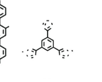
Figure 4.5 Some of the multi-topic linkers.
Figure 4.6 A kind of MOF with multi-hetero topic organic linker.
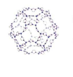
Figure 4.7 (a) Cu(II) Coordination environment. Symmetric nodes: (i) y, 1 - x, 1 - z; (ii) y, x, 1 – z; (iii) 1 - y, x, 1 – z; (iv) 1 – x, y, z; (v) x, 1 – y, z; (vi) -x, 1 – y, z; (vii) -x, y, z; (viii) y, x, -z; (ix) -y, x, -z; (x) y, -x, -z. (b) Distorted truncated octahedron cage: (trinuclear + tetranuclear) SBUs. (c) Illustration of three dimensional porous framework in the considered MOF.
46
47
47
50
58
59
60
61
62
64
65
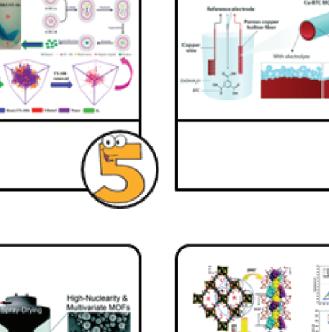
Figure 5.1 Two synthesis strategies to create MMʹ-MOFs. 72
Figure 5.2 Two synthetic methods to create 2D gird MMʹ-MOFs.
Figure 5.3 The incorporated BPDC, RuDCBPY, and PtDCBPY into Zr-MOF (UiO-67) through the solvothermal method. Red balls: SBUs. Gray rod: BPDC. Purple rod: RuDCBPY. Yellow rod: PtDCBPY. This figure is copied with the permission of the mentioned reference.
Figure 5.4 (a) Powder x-ray diffraction patterns, (b) IR spectra, and (c) TGA analysis of UIO-67black, Pt@ UIO-67red, and Ru-Pt@UIO-67blue. (d) Connollysurface-filling model demonstrates mother MOFs of UIO-67 (pore size: 8–10 Å).
Figure 5.5 (a–c) SEM and (d–j) HAADF-STEM images of the considered samples (top). UV-vis of bpdc, RuDCBPY (aqueous solution), and PtDCBPY (MeOH). (a, b) Diffuse reflectance of the considered samples (middle). (c) Powdery samples photographs under natural light (bottom).
Figure 5.6 The formation of coordination polymers from the corresponding metals [4 to 8]/[Cu(2,2ʹbpy)]2+[9]/[10] and metalloligand [LCu].
Figure 5.7 The epitaxial growth of the trimetallic and bimetallic hetero-(Ln)-MOFs from the crystal seed with one type of metal.
Figure 5.8 Transmetalation in porph@MOM-10 (a) and MSO-MOF (b). [Panel (b): metalation after demetalation of MOF].
Figure 5.9 (a) 3D structure of [Gd3Cu12I12(IN)9(DMF)4]n. nDMF. (structure I) (b) [Cu12I12] cluster. (c) Tri-nuclear [Gd3(IN)9(DMF)4] units (top). (a) 3D structure of [Gd4Cu4I3(CO3)2(IN)9(HIN)0.5(DMF) (H2O)]n.nDMF.nH2O. (structure I) (b) [Cu3I2] cluster. (c) Gd4(CO3)2 chains (bottom).
Figure 5.10 The solid-state luminescent properties of MOFs with diverse SBUs.
Figure 5.11 (a and b) MOF 1 structure showing Co3 SBU supported by Co1 and Co2 viewing from two
73
74
75
76
77
79
80
82
85
List of Illustrations xi
directions. (c) Three-dimensional network viewing along the [010] direction.
Figure 6.1 (a) Two types of chiral tetrahedral SBUs. (b) A perspective view of microporous framework: zinc, azury; carbon, gray; oxygen, red. Water molecules of lattice are eliminate for clarity (left). Adsorption isotherm of methane at 298 K, and H2 adsorption desorption isotherms (77 K, inset) activated at 100°C (blue) and 175°C (red) (right and top). Polarization (P) versus applied field (E) hysteresis loops from a single crystal sample (right and bottom).
Figure 6.2 (a) Schematic representation of a chiral MOF catalyst by PSM. (b) The chemical structures of the used chiral ligands based on tetracarboxylic acids.
Figure 6.3 Crystal structure of chiral MOF-1a. (a) Paddle-wheels clusters based on Cu and their connectivity with chiral L1a ligands. (b) L1a: blue distorted tetrahedro; Cu-paddle-wheel cluster: red square. (c) Connectivity of L1a organic ligands and Cu-paddle-wheel node. (d) Stick model. (e) Representation of a simplified connectivity (top). (a–h) Space-filling models of CMOF-1b to -4b with pores size (bottom).
Figure 6.4 (a and b) Views of connectivity around metallic centers in structure 2, highlighting D,L-enantiomeric Cd2+ ions. (c) The onedimensional zigzag coordination chain structure in 2. Cyan: Cd(1); pink: Cd(2) atom; red: oxygen atom; blue: nitrogen atom; gray: carbon atom; yellow: hydrogen atom. α-methyl groups of D-HCam organic ligands: green-colored balls (similar to Zn-analogous 3).
86
108
110
112
117
Figure 6.5 Total synthesis of CMOF with chiral axial ligand. 118
Figure 6.6 Different cavity sizes in CMOFs. 118
List of Illustrations
Figure 6.7 Stick/polyhedra models of CMOF-1-5 with the presence of interpenetration along with connectivity of ligands and SBUs.
Figure 7.1 An example of the chiral templating effect origin.
Figure 7.2 Synthesis method of Ni-PYI1, guest exchange, and the considered asymmetric catalysis.
Figure 7.3 Examples of the post-chiral modification of achiral MOF-NH2 as capillary columns for chiral GC.
Figure 7.4 (a–d) GC chromatograms based on chiral MOFbased columns to separate racemates under different conditions. (a) MIL-101-S-2-Ppa coated column A: 2-methyl-2,4-pentanediol (160°C, 2 ml min−1 N2); 1,2-pentanediol (160°C, 2 ml min−1 N2); citronellal (165°C, 2 ml min−1 N2).
(b) MIL-101-R-Epo coated column B: 2-butanol (150°C, 2 ml min−1 N2); 1-heptyn-3-ol (200°C, 2 ml min−1 N2); citronellal (180°C, 2 ml min−1 N2). (c) MIL-101-(+)-Ac-L-Ta coated column C: 1-amino-2-propanol (210°C, 2 ml min−1 N2); 2-amino-1-butanol (210°C, 2 ml min−1 N2); 1,2-pentanediol (210°C, 3 ml min−1 N2). (d) MIL101-L-Pro coated column D: Mandelonitrile (200°C, 1.8 ml min−1 N2); 1-phenylethylamine (180°C, 2 ml min−1N2); methyl-2chloropropionate (180°C, 2 ml min−1 N2).
Figure 7.5 The example of modified MOF with chiral species through post-chiral modification.
Figure 7.6 Asymmetry unit in Zn-DPYI crystal structure (left). Crystal structure of Zn-DPYI (right).
Figure 7.7 The preparation steps of one kind of chiral Zn-MOF through post-synthesis modification by using two chiral compounds with the opposite chirality.
Figure 8.1 A plot based on the number of published articles about the defect of MOFs.
Figure 8.2 MOF with interpenetration.
119
128
129
132
133
134
134
138
152
153
Figure 8.3 Different cases of MOFs with various mixed linkers. (a) The parent MOF, (b) the different mixed linker structurally, and (c and d) the large and truncated mixed organic linkers. 155
Figure 8.4 MIL to different forms: (a) without any defect, (b) dangling organic linker, and (c) linker vacancy. The orange polyhedral: cationic units. C atom: black. O atom: blue. 156
Figure 8.5 Defective UiO-66(Zr)-(OH)2 framework for CO2 capture.
Figure 9.1 (a) H4PANAD structure. (b) HHU-1 network with varying size pores (two brown atoms illustrate one ellipsoid-like pore). For clarity, H atoms have not been shown.
161
172
Figure 9.2 Heterogeneous pores due to missing node or ligand. 174
Figure 9.3 An example of MOF-based porous carbon (NHOPC) with multiporosity synthesis as a supercapacitor. 176
Figure 9.4 Examples of Cr-MILs as mesoMOFs with two types of mesocages. 178
Figure 10.1 Schematic representation of bio-MOF composite. 187
Figure 10.2 Heteroepitaxially grown hybrid IRMOF-3@1 and structures of IRMOF-1 and IRMOF-3 (zinc: purple; nitrogen: blue; oxygen: red; carbon: gray. Hydrogen atoms have not been shown). 188
Figure 10.4 Isostructural Eu/Tb mixed MOFs with different triplet energy levels. 192
List of Tables
Table 3.1 Examples of mixed ligands metal-organic frameworks. 29
Table 3.2 Determination of catalytic conditions for Biginelli reaction.
Table 5.1 Optimization of the carboxylation of phenylacetylene.
49
83
Table 5.2 Carboxylation of terminal alkynes with CO2. 84
Table 5.3 Crystallographic data and refinement parameters of the considered MOF.
Table 5.4 Various applications of mixed-metal MOFs.
Table 6.1 Diethylzinc additions to aromatic aldehydes.
Table 6.2 Alkynylzinc additions to aromatic aldehydes (similar conditions with Table 6.1).
Table 7.1 Asymmetric dihydroxylation of aryl olefins.
Table 7.2 Aldol reactions catalyzed by Zn-MOF1.
Table 7.3 Aldol reactions by using Zn-MOF1 and Zn-MOF2.
Table 7.4 Control reactions for asymmetric epoxidation of styrene.
Table 7.5 Asymmetric epoxidation of several olefins and methanolysis of styrene oxide.
Table 8.1 Some of the published papers about defects in metal-organic frameworks.
Table 8.2 Some of defective MOF-based materials.
Table 10.1 Carbon dioxide cycloaddition with various epoxides by using CZ-BDO.
87
88
113
114
130
135
136
140
142
151
157
190
List of Schemes
Scheme 2.1 The conversion of an achiral MOF to a chiral MOF by using an achiral organic linker. 19
Scheme 3.1 Structure of the used ligands. 35
Scheme 3.2 Structures of the used organic dyes. 48
Scheme 3.3 Biginelli reaction by using ADES-1. 48
Scheme 6.1 Synthesis conditions to produce chiral metalcamphorate coordination polymers 1–5. 115
Scheme 6.2 Coordination modes of D-Cam and D-HCam in polymeric structures 1–5. 116
Scheme 7.1 Synthesis method of chiral [MIL-101(Cr)-tart]. 137
Scheme 7.2 Interactions in the preparation of [MIL101(Cr)-tart]. 139
Scheme 7.3 The preparation steps of post-chiral modification NU-1000 by SALI method and then Mo-catalyst immobilization on chiral species. 143
Scheme 10.1 Suggested mechanism of carbon dioxide cycloaddition with epoxide by bimetal mixed MOFs. 191
Preface
The study of metal-organic frameworks (MOFs) as porous crystalline materials has risen rapidly over recent years due to their unique properties and various potential applications. Until now, thousands of MOFs have been prepared with wonderful new designs and further precision in the synthesis methods.
As known, MOFs chemistry is started with the main two components: inorganic and organic units. But, it is of interest to know that most of them have homogeneous structure with having one of each kind of component. Recently, MOFs with heterogeneous structures have been attracting strong attention due to their interesting structure and features. These kinds of materials in their body have more kinds of components that lead to structural complexities. The understanding of effective agents in the production of MOFs with heterogeneous structures is another key and important concept that is not easy. Given that how these kinds of heterogeneous porous MOFs are constructed is attractive, so, in this book, we focus on advances in research on MOFs with heterogeneous structures covering mixed components (metals/ligands), multi-heterotopic linkers, defect, heterogeneous pores, mixed MOFs, and, most importantly, chiral MOFs along with some examples. These different cases lead to diversity of parent architectures, and finally, the complexity and heterogeneity appear in them. Many reports have been presented about different kinds of MOFs but some of them are very complex therefore the attempt to their understanding should be increased. This book can help further understanding of these kinds of MOFs.
Ali Morsali and Kayhaneh Berijani Department of Chemistry, Tarbiat Modares University Tehran,
Introduction: A Brief Introduction About Metal-Organic Frameworks
Abstract
Metal-organic frameworks (MOFs) or porous coordination polymers (PCPs) are a subset of hybrid porous materials that have recently attracted considerable attention. Their structures are constructed from inorganic (such as metal clusters or atoms, rod-shaped clusters) and organic (such as carboxylates, azoles, nitriles) parts with different chemical nature. The features of both parts (node and linker) can determine MOF properties like network structure (net) topology, physical, mechanical and morphological features. MOFs with tunable pore size, different functionalization, high surface area and stability can be synthesized through the various synthesis methods. Depending on application of MOFs, design and their synthetic methods can be changed that are very important. Indeed, the rise of MOFs chemistry can be primarily related to their properties and performances. In this chapter, we present a brief introduction about MOFs such as types of metal nodes, organic linkers and synthesis strategies. So, based on the used components in MOFs, diverse frameworks can be designed and generated. As a result, tunability in their structure makes them attractive and important candidates for diverse purposes.
Over almost 20 years, many investigations have been performed about the porous materials field especially metal-organic frameworks (MOFs) as a subset of porous coordination polymers (PCPs). For the
first time, these compounds were defined by Yaghi and co-workers in 1995. The considerable attention to MOFs is due to their chemical and physical properties such as variety in building units and design, pore size, and cavity shape that lead to different frameworks with diverse applications. In the growth of these compounds and their introduction, several scientific groups are trying. The most important and famous MOFs are MOF-5 (zinc salt and H2BDC), HKUST-1 (copper salt and H3BTC), MIL-101 (chromium/iron salt and H2BDC), and MOF-74 (zinc salt and H2-DHBDC). As known, the reticular structures of MOFs can be made from two sections: inorganic nodes and organic linkers (sometimes with functional group). Simple description of 3D MOF chemistry has been shown in Figure 1.1.
Diverse building blocks can be used in the synthesis of any MOF, for example, metal units as node including lanthanide cations, transition metals, heavy transition metals and main metal ions, organic linkers like carboxylates linkers, and N-donor ligands that can be ditopic or polytopic. So, unlimited number of frameworks can be created with different features, geometries, and structures. Whereas, these components as building blocks can affect MOFs properties, so they should be carefully selected. In the following, we show some examples of SBUs (secondary building units), linkers, and MOFs although there are the various building units (Figure 1.2) [1, 2].
Figure 1.1 Simple description of 3D MOF chemistry [1].
It is worthy to note that stability and instability of MOFs are closely related to the used components and their coordination bonding (between metal moiety and organic linker). In the construction of these PCPs with crystalline networks, the coordination bonds are formed between building units. They have desirable features such as large surface area, adjustable pores, appropriate porosity, and crystalline structure with different topologies [3–5]. In addition, the body of MOFs, from metal nodes to linkers, can be functionalized with various functional groups through different strategies such as incorporation of the intended groups by post-synthesis modification (PSM) as straightforward approach. The ideal tunability in MOFs constituents leads to various platforms with different applications
1.2 Some examples of metal nodes, organic linkers, and MOFs (definition of atom types:
(Continued)
Metal Node
M = Cu, Zn M = Zn, Co, Ni, Cu M = Zn, Ti, V, Cr, Mn, Fe
Figure 1.2 (Continued) Some examples of metal nodes, organic linkers, and MOFs (definition of atom types: blue: metal; red: oxygen; purple: nitrogen; gray: carbon; and green: chlorine). (Continued)
Metal-Organic Frameworks
Figure 1.2 (Continued) Some examples of metal nodes, organic linkers, and MOFs (definition of atom types: blue: metal; red: oxygen; purple: nitrogen; gray: carbon; and green: chlorine).
ZIF-71
M-BT T
HKUST-1
Bio -MOF
Pillared Paddlewheel
UiO-66
MIL-53
MFU-4/ SNU-51
CPO-27 MOF-74
even in the industrial scale as catalysis, gas storage, supercapacitors, medical uses, separation, sensing, and so on. In fact, owing to the facile ability to functionalize such materials, MOFs have found suitability for a range of applications. Certainly, there are some difficulties and limitations to prepare the plausible nets of MOFs such as temperature, solvent, stability, geometry building blocks, kind of the used metal/ligand, and their solubility. Nowadays, new ideas and valuable efforts have been aimed to the successful synthesis of new MOFs with remarkable designs and useful properties, because MOFs have the desirable potential due to the flexibility in choosing the structural components. Until now, different approaches to synthesize porous MOFs have been generally reported such as solvothermal or sonochemical syntheses. But, day to day, the development in new or optimized synthetic methodologies accelerates the creation of new structures with different features. As an example, Hwang et al. reported the different synthetic methods in Fe‐BTC hydrothermal synthesis based on change in time or temperature reaction, or Yang et al. presented conditions of hydrothermal synthesis in the generation of HKUST‐1 based on change in time and solvent. Some synthesis methods have been introduced in Figure 1.3. In all of them, the optimal conditions of synthesis methods have been investigated with their advantages and disadvantages. However, MOFs can be easily manipulated and modified by the adjustment of the components and synthesis conditions [6–15]. Indeed, their consistuents enable the preparation of different frameworks with various sizes through a broad spectrum of synthetic methods like solvothermal (such as hydrothermal synthesis: it refers to synthesis through chemical reactions in an aqueous solution above the boiling point of water), electrochemical method (direct or indirect synthesis; Unlike indirect synthesis, in which electrochemistry is only a step in an overall synthesis method, direct route allows synthesis rate control by electrochemical means) [16–19], sonochemical synthesis (using powerful ultrasound radiation (20 kHz–10 MHz)), [20, 21] mechanochemical synthesis (a processing method of solids in which mechanical and chemical phenomena are coupled on a molecular scale) and so on [22–24]. As mentioned, depending on the synthesis conditions and compositions, properties of MOF can be changed toward new and modified features. So, structural flexibility and diversity of MOFs that
can be originated from synthetic methods can promote and improve frameworks and their applications. For example, the combination of 1,4-benzenedicarboxylate and Zn leads to 1D linear structure. It is interesting that 2D layered structure and 3D network can be also produced by using these starting materials through interactions such as hydrogen bond and π-π stacking [25, 26]. So, due to a great number of metal nodes and organic linkers, designed new well-defined MOFs through different syntheses can be created. Most porous MOFs have homogeneous structures without any heterogeneity or complexity in their structure. The term of “complexity” in materials has received a great deal of attention in scientific fields. However, complexity in
Figure 1.3 Some examples of MOFs synthesis methods.
8 MOFs with Heterogeneous Structures
systems has a long history in science. In this book, we introduce some effective factors in the production of heterogeneous structures of MOFs by their structural complexity and heterogeneity. Certainly, book chapters can provide creativity for new research and describe a number of significant and different up-to-date strategies about the generation of complex MOFs.
1.2 Conclusion
Until now, many investigations have been performed in MOFs field from synthesis approaches to analytical characterizations along with theoretical calculations. According to the capabilities of MOFs and their derived materials, investigation and use of them have been increased in the different fields such as optical and electrochemical sensors, catalysis, gas storage/separation, drug delivery, and ion-conduction. Indeed, the rise of chemistry about MOFs can be ascribed to the relationship between physical and chemical features of MOFs with their structure/composition like pore size, surface area, active sites, stability, and interaction degree. Most frameworks based on MOF are in homogeneous form, but recently, considerable efforts have been devoted to the creation of robust, stable MOFs with heterogeneous structures. So, establishment of several rational strategies for generating complex MOFs with developing new process conditions has attracted much more attention. In relation to MOFs with heterogeneous structures, the next chapters discuss the introduction of the kinds of complexities and their progresses in MOFs.
References
1. Moosavi, S.M., Nandy, A., Jablonka, K.M., Ongari, D., Janet, J.P., Boyd, P.G., Lee, Y., Smit, B., Kulik, H., Understanding the diversity of the metal-organic framework ecosystem. Nat. Commun., 11, 4068, 2020.
2. Furukawa, H., Cordova, K.E., O’Keeffe, M., Yaghi, O.M., The chemistry and applications of metal-organic frameworks. Science, 341, 6149, 1230444, 2013.
3. Furukawa, H., Ko, N., Go, Y.B., Aratani, N., Choi, S.B., Choi, E., Yazaydin, A.O., Snurr, R.Q., O’Keeffe, M., Kim, J., Yaghi, O.M., Ultrahigh porosity in metal-organic frameworks. Science, 329, 424–428, 2010.
4. Chen, S.S., Hu, C., Liu, C.H., Chen, Y.H., Ahamad, T., Alshehri, S.M., Huang, P.H., Wu, K.C.W., De Novo synthesis of platinumnanoparticle-encapsulated UiO-66-NH2 for photocatalytic thin film fabrication with enhanced performance of phenol degradation. J. Hazard. Mater., 397, 122431, 2020.
5. Ghasempour, H. and Morsali, A., Function-Topology Relationship in Catalytic Hydrolysis of Chemical Warfare Simulant inTwo Zr-MOFs. Chem.–Eur. J, 2020, 26, 17437–17444, 2020.
6. Berijani, K., Morsali, A., Hupp, J.T., An Effective Strategy for Creating Asymmetric MOFs for Chirality Induction: A Chiral Zr-based MOF for Enantioselective Epoxidation. Catal. Sci. Technol., 9, 3388–3397, 2019.
7. Ghasempour, H., Wang, K.Y., Powell, J.A., ZareKarizi, F., Lv, X.L., Morsali, A., Zhou, H.C., Metal–organic frameworks based on multicarboxylate linkers. Coord. Chem. Rev., 426, 213542, 2021.
9. Razavi, S.A.A., Berijani, K., Morsali, A., Hybrid nanomaterials for asymmetric purposes: green enantioselective C–C bond formation by chiralization and multi-functionalization approaches. Catal. Sci. Technol., 2020, 10, 8240–8253, 2020.
10. Li, Z., Liu, P., Ou, C., Dong, X., Porous Metal–Organic Frameworks for Carbon Dioxide Adsorption and Separation at Low Pressure. ACS Sustain. Chem. Eng., 8, 41, 15378–15404, 2020.
11. Valekar, A.H., Lee, M., Yoon, J.W., Kwak, J., Hong, D.Y., Oh, K.R., Cha, G.Y., Kwon, Y.U., Jung, J., Chang, J.S., Hwang, Y.K., Catalytic transfer hydrogenation of furfural to furfuryl alcohol under mild conditions over Zr-MOFs: Exploring the role of metal node coordination and modification. ACS Catal., 10, 6, 3720–3732, 2020.
12. Zhang, M., Ding, X., Zhan, Y., Wang, Y., Wang, X., Improving the flame retardancy of poly (lactic acid) using an efficient ternary hybrid flame retardant by dual modification of graphene oxide with phenylphosphinic acid and nano MOFs. J. Hazard. Mater., 384, 121260, 2020.
13. Kalaj, M. and Cohen, S.M., Postsynthetic Modification: An Enabling Technology for the Advancement of Metal–Organic Frameworks. ACS Cent. Sci., 6, 7, 1046–1057, 2020.
14. Xu, C., Ai, Y., Zheng, T., Wang, C., Acoustic manipulation of breathing MOFs particles for self-folding composite films preparation. Sens. Actuators A: Phys., 315, 112288, 2020.
15. Peng, J., Li, Y., Sun, X., Huang, C., Jin, J., Wang, J., Chen, J., Controlled Manipulation of MOFs Layers to Nanometer Precision inside large Meso-channels of Ordered Mesoporous Silica for Enhanced Removal of Bisphenol A from Water. ACS Appl. Mater. Interfaces, 11, 4, 4328–4337, 2019.
17. Lestari, W.W., Winarni, I.D., Rahmawati, F., Electrosynthesis of MetalOrganic Frameworks (MOFs) Based on Nickel (II) and Benzene 1, 3, 5-Tri Carboxylic Acid (H3BTC): An Optimization Reaction Condition. In IOP Conf. Ser.: Mater. Sci. Eng., 172, 1, 012064, 2017.
18. Ji, L., Hao, J., Wu, K., Yang, N., Potential-Tunable Metal–Organic Frameworks: Electrosynthesis, Properties, and Applications for Sensing of Organic Molecules. J. Phys. Chem. C, 123, 4, 2248–2255, 2019.
19. Kumar, R.S., Kumar, S.S., Kulandainathan, M.A., Efficient electrosynthesis of highly active Cu3(BTC)2-MOF and its catalytic application to chemical reduction. Micropor. Mesopor. Mater., 168, 57–64, 2013.
20. Yu, K., Lee, Y.R., Seo, J.Y., Baek, K.Y., Chung, Y.M., Ahn, W.S., Sonochemical synthesis of Zr-based porphyrinic MOF-525 and MOF545: Enhancement in catalytic and adsorption properties. Micropor. Mesopor. Mater., 316, 110985, 2021.
21. Wiwasuku, T., Othong, J., Boonmak, J., Ervithayasuporn, V., Youngme, S., Sonochemical synthesis of microscale Zn(ii)-MOF with dual Lewis basic sites for fluorescent turn-on detection of Al3+ and methanol with low detection limits. Dalton Trans., 49, 29, 10240–10249, 2020.
22. Chen, D., Zhao, J., Zhang, P., Dai, S., Mechanochemical synthesis of metal–organic frameworks. Polyhedron, 162, 59–64, 2019.
23. Klimakow, M., Klobes, P., Thünemann, A.F., Rademann, K., Emmerling, F., Mechanochemical synthesis of metal−organic frameworks: a fast and facile approach toward quantitative yields and high specific surface areas. Chem. Mater., 22, 18, 5216–5221, 2010.
Introduction About MOFs 11
24. Singh, N.K., Hardi, M., Balema, V.P., Mechanochemical synthesis of an yttrium based metal–organic framework. Chem. Commun., 49, 10, 972–974, 2013.
25. Rodrigues, M.O., de Paula, M.V., Wanderley, K.A., Vasconcelos, I.B., Alves Jr, S., Soares, T.A., Metal organic frameworks for drug delivery and environmental remediation: A molecular docking approach. Int. J. Quantum Chem., 112, 20, 3346–3355, 2012.
26. Suh, M.P., Park, H.J., Prasad, T.K., Lim, D.-W., Hydrogen storage in metal–organic frameworks. Chem. Rev., 112, 782–835, 2012.