Polymer Composites for Electrical Engineering
Edited by
Xingyi Huang
Shanghai Key Laboratory of Electrical Insulation and Thermal Aging, Shanghai
Jiao Tong University, Shanghai, China
Toshikatsu Tanaka
Waseda University, Tokyo, Japan
This edition first published 2022 © 2022 John Wiley & Sons Ltd
All rights reserved. No part of this publication may be reproduced, stored in a retrieval system, or transmitted, in any form or by any means, electronic, mechanical, photocopying, recording or otherwise, except as permitted by law. Advice on how to obtain permission to reuse material from this title is available at http://www.wiley.com/go/permissions.
The right of Xingyi Huang and Toshikatsu Tanaka to be identified as the authors of the editorial material in this work has been asserted in accordance with law.
Registered Offices
John Wiley & Sons, Inc., 111 River Street, Hoboken, NJ 07030, USA
John Wiley & Sons, Ltd., The Atrium, Southern Gate, Chichester, West Sussex, PO19 8SQ, UK
Editorial Office
The Atrium, Southern Gate, Chichester, West Sussex, PO19 8SQ, UK
For details of our global editorial offices, customer services, and more information about Wiley products visit us at www.wiley.com.
Wiley also publishes its books in a variety of electronic formats and by print-on-demand. Some content that appears in standard print versions of this book may not be available in other formats.
Limit of Liability/Disclaimer of Warranty
While the publisher and authors have used their best efforts in preparing this work, they make no representations or warranties with respect to the accuracy or completeness of the contents of this work and specifically disclaim all warranties, including without limitation any implied warranties of merchantability or fitness for a particular purpose. No warranty may be created or extended by sales representatives, written sales materials or promotional statements for this work. The fact that an organization, website, or product is referred to in this work as a citation and/or potential source of further information does not mean that the publisher and authors endorse the information or services the organization, website, or product may provide or recommendations it may make. This work is sold with the understanding that the publisher is not engaged in rendering professional services. The advice and strategies contained herein may not be suitable for your situation. You should consult with a specialist where appropriate. Further, readers should be aware that websites listed in this work may have changed or disappeared between when this work was written and when it is read. Neither the publisher nor authors shall be liable for any loss of profit or any other commercial damages, including but not limited to special, incidental, consequential, or other damages.
Library of Congress Cataloging-in-Publication Data Applied for:
[HB ISBN: 9781119719601]
Cover Design: Wiley
Cover Image: © Nikifor Todorov
Set in 9.5/12.5pt STIXTwoText by Straive, Pondicherry, India
10 9 8 7 6 5 4 3 2 1
Contents
List of Contributors xv Preface xix
1 Polymer Composites for Electrical Energy Storage 1
Yao Zhou
1.1 Introduction 1
1.2 General Considerations 1
1.3 Effect of Nanofiller Dimension 3
1.4 Orientation of Nanofillers 7
1.5 Surface Modification of Nanofillers 11
1.6 Polymer Composites with Multiple Nanofillers 13
1.7 Multilayer-structured Polymer Composites 16
1.8 Conclusion 19
References 21
2 Polymer Composites for Thermal Energy Storage 29
Jie Yang, Chang-Ping Feng, Lu Bai, Rui-Ying Bao, Ming-Bo Yang, and Wei Yang
2.1 Introduction 29
2.2 Shape-stabilized Polymeric Phase Change Composites 32
2.2.1 Micro/Nanoencapsulated Method 33
2.2.2 Physical Blending 35
2.2.3 Porous Supporting Scaffolds 36
2.2.4 Solid–Solid Composite PCMs 37
2.3 Thermally Conductive Polymeric Phase Change Composites 39
2.3.1 Metals 40
2.3.2 Carbon Materials 41
2.3.3 Ceramics 41
2.4 Energy Conversion and Storage Based on Polymeric Phase Change Composites 42
2.4.1 Electro-to-Heat Conversion 42
2.4.2 Light-to-Heat Conversion 45
2.4.3 Magnetism-to-Heat Conversion 47
2.4.4 Heat-to-Electricity Conversion 48
2.5 Emerging Applications of Polymeric Phase Change Composites 48
2.5.1 Thermal Management of Electronics 49
2.5.2 Smart Textiles 50
2.5.3 Shape Memory Devices 51
2.6 Conclusions and Outlook 51
Acknowledgments 52
References 52
3 Polymer Composites for High-Temperature Applications 63 Sen Niu, Lixue Zhu, Qiannan Cai, and Yunhe Zhang
3.1 Application of Polymer Composite Materials in High-Temperature Electrical Insulation 63
3.1.1 High-Temperature-Resistant Electrical Insulating Resin Matrix 63
3.1.1.1 Silicone Resins 64
3.1.1.2 Polyimide 64
3.1.1.3 Polyether Ether Ketone 65
3.1.1.4 Polybenzimidazole 65
3.1.1.5 Polyphenylquinoxaline 65
3.1.1.6 Benzoxazine 66
3.1.2 Modification of Resin Matrix with Reinforcements 66
3.1.2.1 Mica 66
3.1.2.2 Glass Fiber 66
3.1.2.3 Inorganic Nanoparticles 67
3.1.3 Modifications in the Thermal Conductivity of Resin Matrix 67
3.1.3.1 Mechanism of Thermal Conductivity 68
3.1.3.2 Intrinsic High Thermal Conductivity Insulating Material 68
3.1.3.3 Filled High Thermal Conductivity Insulating Material 69
3.2 High-Temperature Applications for Electrical Energy Storage 70
3.2.1 General Considerations for High-Temperature Dielectrics 70
3.2.2 High-Temperature-Resistant Polymer Matrix 71
3.2.3 Polymer Composites for High-Temperature Energy Storage Applications 71
3.2.4 Surface Modification of Nanocomposite for High-Temperature Applications 72
3.2.5 Sandwich Structure of Nanoparticles for High-Temperature Applications 75
3.3 Application of High-Temperature Polymer in Electronic Packaging 77
3.3.1 Synthesis of Low Dielectric Constant Polymer Materials Through Molecular Structure Design 80
3.3.1.1 Fluorine- Containing Low Dielectric Constant Polymer 80
3.3.1.2 Low Dielectric Constant Polymer Material Containing Nonpolar Rigid Bulk Group 81
3.3.2 High-Temperature-Resistant Low Dielectric Constant Polymer Composite Material 82
3.3.2.1 Low Dielectric Constant Polyoxometalates/Polymer Composite 83
3.3.2.2 Low Dielectric Constant POSS/Polymer Composite 85
3.4 Application of Polymer Composite Materials in the Field of High-Temperature Wave-Transmitting and Wave-Absorbing Electrical Fields 86
3.4.1 Wave-Transmitting Materials 88
3.4.1.1 The High-Temperature Resin Matrix 88
3.4.1.2 Reinforced Materials 89
3.4.2 Absorbing Material 89
3.4.2.1 The High-Temperature Resin Matrix 90
3.4.2.2 Inorganic Filler 90
3.5 Summary 91
References 92
4 Fire-Retardant Polymer Composites for Electrical Engineering 99
Zhi Li, En Tang, and Xue-Meng Cao
4.1 Introduction 99
4.2 Fire-Retardant Cables and Wires 100
4.2.1 Fundamental Overview 100
4.2.2 Understanding of Fire-Retardant Cables and Wires 101
4.2.2.1 Polyethylene Composites 101
4.2.2.2 Ethylene-Vinyl Acetate (EVA) Copolymer 103
4.2.2.3 Polyvinyl Chloride Composites 105
4.2.2.4 Other Polymers 108
4.3 Fire-Retardant Polymer Composites for Electrical Equipment 109
4.3.1 Fundamental Overview 109
4.3.2 Understanding of Fire-Retardant Polymer Composites for Electrical Equipment 110
4.3.2.1 HIPS and ABS Composites 110
4.3.2.2 PC/ABS Composites 112
4.3.2.3 PC Composites 115
4.3.2.4 PBT Composites 116
4.4 Fire-Retardant Fiber Reinforced Polymer Composites 117
4.4.1 Fundamental Overview 117
4.4.2 Understanding of Fire-Retardant Fiber Reinforced Polymer Composites 118
4.4.2.1 Reinforced PBT and PET Composites 118
4.5 Conclusion and Outlook 118
References 119
5 Polymer Composites for Power Cable Insulation 123
Yoitsu Sekiguchi
5.1 Introduction 123
5.2 Trend in Nanocomposite Materials for Cable Insulation 125
5.2.1 Overview 125
5.2.2 Polymer Materials as Matrix Resin 125
5.2.3 Fillers 128
5.2.4 Nanocomposites 130
5.2.4.1 XLPE Nanocomposites 131
5.2.4.2 PP Nanocomposites 131
5.2.4.3 Nanocomposite with Cluster/Cage Molecule 131
5.2.4.4 Copolymer and Polymer Blend 131
5.3 Factors Influencing Properties 138
5.4 Issues in Nanocomposite Insulation Materials Research 139
5.5 Understanding Dielectric and Insulation Phenomena 140
5.5.1 Electromagnetic Understanding 140
5.5.2 Understanding Space Charge Behavior by Q(t) Method 141 References 146
6 Semi-conductive Polymer Composites for Power Cables 153 Zhonglei Li, Boxue Du, Yutong Zhao, and Tao Han
6.1 Introduction 153
6.1.1 Function of Semi-conductive Composites 153
6.1.2 Development of Semi-conductive Composites 154
6.2 Conductive Mechanism of Semi-conductive Polymer Composites 155
6.2.1 Percolation Theory 157
6.2.2 Tunneling Conduction Theory 157
6.2.3 Mechanism of Positive Temperature Coefficient 158
6.3 Effect of Polymer Matrix on Semi-conductivity 159
6.3.1 Thermoset Polymer Matrix 159
6.3.2 Thermoplastic Polymer Matrix 162
6.3.3 Blended Polymer Matrix 163
6.4 Effect of Conductive Fillers on Semi-conductivity 165
6.4.1 Carbon Black 165
6.4.2 Carbonaceous Fillers with One- and Two-Dimensions 166
6.4.3 Secondary Filler for Carbon Black Filled Composites 167
6.5 Effect of Semi-conductive Composites on Space Charge Injection 169
6.6 Conclusions 172
References 173
7 Polymer Composites for Electric Stress Control 179
Muneaki Kurimoto
7.1 Introduction 179
7.2 Functionally Graded Solid Insulators and Their Effect on Reducing Electric Field Stress 179
7.3 Practical Application of ε-FGMs to GIS Spacer 181
7.4 Application to Power Apparatus 182 References 188
8 Composite Materials Used in Outdoor Insulation 191 Wang Xilin, Jia Zhidong, and Wang Liming
8.1 Introduction 191
8.2 Overview of SIR Materials 192
8.2.1 RTV Coatings 193
8.2.2 Composite Insulators 195
8.2.3 Liquid Silicone Rubber (LSR) 196
8.2.4 Aging Mechanism and Condition Assessment of SIR Materials 197
8.3 New External Insulation Materials 198
8.3.1 Anti-icing Semiconductor Materials 199
8.3.2 Hydrophobic CEP 201
8.4 Summary 202
References 203
9 Polymer Composites for Embedded Capacitors 207
Shuhui Yu, Suibin Luo, Riming Wang, and Rong Sun
9.1 Introduction 207
9.1.1 Development of Embedded Technology 207
9.1.2 Dielectric Materials for Commercial Embedded Capacitors 210
9.2 Researches on the Polymer-Based Dielectric Nanocomposites 213
9.2.1 Filler Particles 213
9.2.2 Epoxy Matrix 216
9.2.2.1 Modification to Improve Dielectric Properties 219
9.2.2.2 Modification to Improve Mechanical Properties 221
9.3 Fabrication Process of Embedded Capacitors 224
9.4 Reliability Tested of Embedded Capacitor Materials 229
9.5 Conclusions and Perspectives 230
References 230
10 Polymer Composites for Generators and Motors 235
Hirotaka Muto, Takahiro Umemoto, and Takahiro Mabuchi
10.1 Introduction 235
10.2 Polymer Composite in High-Voltage Rotating Machines 236
10.3 Ground Wall Insulation 237
10.3.1 Mica/Epoxy Insulation 237
10.3.2 Electrical Defect in the Insulation of Rotating Machines and Degradation Mechanism 238
10.3.3 Insulation Design and V-t Curve 239
10.4 Polymer Nanocomposite for Rotating Machine 240
10.4.1 Partial Discharge Resistance and a Treeing Lifetime of Nanocomposite as Material Property 241
10.4.1.1 PD Resistance 241
10.4.1.2 Electrical Treeing Lifetime 242
10.4.2 Breakdown Lifetime Properties of Realistic Insulation Defect in Rotating Machine 244
10.4.2.1 Voltage Endurance Test of Void Defect 245
10.4.2.2 Voltage Endurance Test in Mica/Epoxy Nanocomposite-Layered Structure 247
10.4.2.3 V-t Curves in Coil Bar Model with Mica/Epoxy Nanocomposite Insulation 248
10.5 Stress-Grading System of Rotating Machines 252
10.5.1 Silicon Carbide Particle-Loaded Nonlinear-Resistive Materials 252
Contents x
10.5.2 End-turn Stress-Grading System of High-Voltage Rotating Machines 253 References 255
11 Polymer Composite Conductors and Lightning Damage 259 Xueling Yao
11.1 Lightning Environment and Lightning Damage Threat to Composite-Based Aircraft 259
11.1.1 The Lightning Environment 259
11.1.1.1 Formation of Lightning 259
11.1.2 Lightning Test Environment of Aircrafts 261
11.1.2.1 Zone 1 262
11.1.2.2 Zone 2 263
11.1.2.3 Zone 3 263
11.1.2.4 Current Component A – First Return Strike 264
11.1.2.5 Current Component Ah – Transition Zone First Return Strike 264
11.1.2.6 Current Component B – Intermediate Current 264
11.1.2.7 Current Component C – Continuing Current 264
11.1.2.8 Component C* – Modified Component C 264
11.1.2.9 Current Component D – Subsequent Strike Current 266
11.1.3 Waveform Combination in Different Lightning Zones for Lightning Direct Effect Testing 269
11.1.4 Application of CFRP Composites in Aircraft 269
11.2 The Dynamic Conductive Characteristics of CFRP 271
11.2.1 A Review of the Research on the Conductivity of CFRP 271
11.2.2 The Testing Methods 272
11.2.2.1 Specimens 272
11.2.2.2 The Test Fixture 273
11.2.2.3 Lightning Impulse Generator and Lightning Waveforms 274
11.2.3 The Experimental Results of the Dynamic Impedance of CFRP 275
11.2.3.1 The Nondestructive Lightning Current Test 275
11.2.3.2 The Applied Lightning Current Impulse and the Response Voltage Impulse 278
11.2.3.3 Equivalent Conductivity of CFRP Laminates Under Different Lightning Impulses 280
11.2.3.4 Equivalent Conductivity of CFRP Laminates with Different Laminated Structures 282
11.2.4 The Discussion of the Dynamic Conductive Characteristics of CFRP 282
11.2.4.1 The Conduction Path of the CFRP Laminate Under a Lightning Current Impulse 282
11.2.4.2 Dynamic Conductance of CFRP Laminate 284
11.2.4.3 The Inductive Properties of CFRP Laminates 286
11.2.4.4 Equivalent Conductivity of CFRP Laminates Subjected to Lightning Current Impulses with Higher Intensity 288
11.3 The Lightning Strike-Induced Damage of CFRP Strike 289
11.3.1 Introduction of the Lightning Damage of CFRP 289
11.3.2 Single Lightning Strike-Induced Damage 290
11.3.2.1 Experimental Setup for Single Lightning Strike Test 290
11.3.2.2 Experimental Results of Single Lightning Strike-Induced Damage 292
11.3.2.3 Evaluation for Single Lightning Strike-Induced Damage 297
11.3.3 Multiple Lightning Strikes-Induced Damage 300
11.3.3.1 Experimental Method for Multiple Consecutive Lightning Strike Tests 300
11.3.3.2 Experimental Results of Multiple Lightning Damage 303
11.3.3.3 Multiple Lightning Damage Areas and Depths of CFRP Laminates 308
11.3.3.4 Analysis for Multiple Lightning Damage of CFRP Laminates 309
11.3.3.5 Evaluation for Multiple Lightning Damage of CFRP Laminates 313
11.4 The Simulation of Lightning Strike-Induced Damage of CFRP 319
11.4.1 Overview of Lightning Damage Simulation Researches 319
11.4.2 Establishment of the Coupled Thermal-Electrical Model 321
11.4.2.1 Finite Element Model 321
11.4.2.2 Simulated Lightning Component A 322
11.4.2.3 Pyrolysis Degree Calculation 322
11.4.2.4 Dynamic Conductive Properties 322
11.4.2.5 Pyrolysis-Dependent Material Parameters 323
11.4.3 Simulation Physical Fields of Lightning Current on CFRP Laminates 323
11.4.3.1 Temperature and Pyrolysis Fields 323
11.4.3.2 Mechanical Analysis 325
11.4.4 Simulated Lightning Damage Results 325
11.4.4.1 Numerical Criterion for Lightning Damage 325
11.4.4.2 In-Plane Lightning Damage Evaluation 327
11.4.4.3 In-Depth Lightning Damage Evaluation 331 References 331
12 Polymer Composites for Switchgears 339
Takahiro Imai
12.1 Introduction 339
12.2 History of Switchgear 340
12.3 Typical Insulators in Switchgears 342
12.3.1 Epoxy-based Composite Insulators 342
12.3.2 Insulator-Manufacturing Process 343
12.3.2.1 Vacuum Casting Method 344
12.3.2.2 Automatic Pressure Gelation Method 344
12.3.2.3 Vacuum Pressure Impregnation Method 345
12.4 Materials for Epoxy-based Composites 345
12.4.1 Epoxy Resins 345
12.4.2 Hardeners 346
12.4.3 Inorganic Fillers and Fibers 347
12.4.4 Silane Coupling Agents 348
12.4.5 Fabrication of Epoxy-based Composites 349
12.5 Properties of Epoxy-based Composites 351
12.5.1 Necessary Properties of Epoxy-based Composites for Switchgears 351
12.5.2 Resistance to Thermal Stresses 352
12.5.2.1 Glass Transition Temperature 352
12.5.2.2 Coefficient of Thermal Expansion (CTE) 354
12.5.3 Resistances to Electrical Stresses 356
12.5.3.1 Short-term Insulation Breakdown 356
12.5.3.2 Long-term Insulation Breakdown (V-t Characteristics) 357
12.5.3.3 Relative Permittivity and Resistivity 359
12.5.4 Resistances to Ambient Stresses 360
12.5.4.1 Resistance to SF6 Decomposition Gas 360
12.5.4.2 Water Absorption 361
12.5.5 Resistances to Mechanical Stresses 362
12.5.5.1 Flexural and Tensile Strength 362
12.5.5.2 Creep 363
12.5.6 International Standards for Evaluation of Composites 363
12.6 Advances of Epoxy-based Composites for Switchgear 365
12.6.1 Nanocomposites 365
12.6.2 High Thermal Conductive Composites 366
12.6.3 Biomass Material-Based Composites 367
12.6.4 Functionally Graded Materials 368
12.6.5 Estimate of Remaining Life of Composites 370
12.7 Conclusion 372
References 373
13 Glass Fiber-Reinforced Polymer Composites for Power Equipment 377 Yu Chen
13.1 Overview 377
13.2 Glass Fiber-Reinforced Polymer Composites 378
13.2.1 Fibers 378
13.2.1.1 Chemical Description 378
13.2.1.2 Classification of Glass Fibers 380
13.2.1.3 Properties of Glass Fiber 380
13.2.1.4 Glass Fabrics 380
13.2.1.5 Advantages and Disadvantages 381
13.2.1.6 Common Manufacturing Methods 383
13.2.1.7 Applications of Glass Fiber in Various Industries 384
13.2.2 Polymers 386
13.2.2.1 Epoxy 386
13.2.2.2 Polyester (Thermosetting) 386
13.2.2.3 Phenolic 387
13.2.3 Manufacturing Methods 388
13.2.4 Specifications of Several Kinds of GFRP Materials 393
13.2.4.1 Rigid Laminated Sheets 393
13.2.4.2 Industrial Rigid Round Laminated Rolled Tubes 394
13.2.4.3 Insulated Pipe 394
13.2.4.4 Insulated Pull Rod 394
13.3 Application of Glass Fiber-Reinforced Polymer Composites 396
13.3.1 Laminated Sheets 396
13.3.2 Composite Long Rod Insulators 398
13.3.3 UHV-Insulated Pull Rod for GIS 400
13.3.4 Composite Pole 403
13.3.5 Aluminum Conductor Composite Core in an Overhead Conductor 404
13.3.6 Composite Station Post Insulators 405
13.3.7 Composite Hollow Insulators 407
13.3.8 Composite Crossarms 407
Bibliography 414
Index 419
List of Contributors
Lu Bai
College of Polymer Science and Engineering, Sichuan University, State Key Laboratory of Polymer Materials Engineering, Chengdu, Sichuan, P. R. China
Rui-Ying Bao
College of Polymer Science and Engineering, Sichuan University, State Key Laboratory of Polymer Materials Engineering, Chengdu, Sichuan, P. R. China
Qiannan Cai
Key Laboratory of High Performance Plastics (Jilin University), Ministry of Education. College of Chemistry, Jilin University, Changchun, P. R. China
Xue-Meng Cao
China-Spain Collaborative Research Center for Advanced Materials, School of Materials Science and Engineering, Chongqing Jiaotong University, Chongqing, China
Yu Chen
School of Electrical Engineering, Xi’an Jiaotong University, Xi’an, China
Boxue Du
Key Laboratory of Smart Grid of Education Ministry, School of Electrical
and Information Engineering, Tianjin University, Tianjin, China
Chang-Ping Feng
College of Polymer Science and Engineering, Sichuan University, State Key Laboratory of Polymer Materials Engineering, Chengdu, Sichuan, P. R. China
Tao Han
Key Laboratory of Smart Grid of Education Ministry, School of Electrical and Information Engineering, Tianjin University, Tianjin, China
Takahiro Imai
Infrastructure Systems Research and Development Center, Toshiba Infrastructure Systems & Solutions Corporation, Toshiba-cho, Fuchu-shi, Tokyo, Japan
Muneaki Kurimoto
Nagoya University, Furo-cho, Chikusa-ku, Nagoya, Japan
Zhi Li
China-Spain Collaborative Research Center for Advanced Materials, School of Materials Science and Engineering, Chongqing Jiaotong University, Chongqing, China
List of Contributors
Zhonglei Li
Key Laboratory of Smart Grid of Education Ministry, School of Electrical and Information Engineering, Tianjin University, Tianjin, China
Wang Liming
Engineering Laboratory of Power Equipment Reliability in Complicated Coastal Environments, Tsinghua Shenzhen International Graduate School, Tsinghua University, Shenzhen, Guangdong, China
Suibin Luo
Shenzhen Institute of Advanced Electronic Materials, Shenzhen Institutes of Advanced Technology, Chinese Academy of Sciences, Shenzhen, China
Takahiro Mabuchi
Advanced Technology Research and Development Center, Mitsubishi Electric Corporation, Amagasaki-shi, Tokyo, Japan
Hirotaka Muto
Advanced Technology Research and Development Center, Mitsubishi Electric Corporation, Amagasaki-shi, Tokyo, Japan
Sen Niu
Key Laboratory of High Performance Plastics (Jilin University), Ministry of Education. College of Chemistry, Jilin University, Changchun, P. R. China
Yoitsu Sekiguchi
Sumitomo Electric Industries, Ltd., Osaka, Japan
Rong Sun
Shenzhen Institute of Advanced Electronic Materials, Shenzhen Institutes of Advanced Technology, Chinese Academy of Sciences, Shenzhen, China
En Tang
China-Spain Collaborative Research Center for Advanced Materials, School of Materials Science and Engineering, Chongqing Jiaotong University, Chongqing, China
Takahiro Umemoto
Advanced Technology Research and Development Center, Mitsubishi Electric Corporation, Amagasaki-shi, Tokyo, Japan
Wang Xilin
Engineering Laboratory of Power Equipment Reliability in Complicated Coastal Environments, Tsinghua Shenzhen International Graduate School, Tsinghua University, Shenzhen, Guangdong, China
Jie Yang
College of Polymer Science and Engineering, Sichuan University, State Key Laboratory of Polymer Materials Engineering, Chengdu, Sichuan, P. R. China
Ming-Bo Yang
College of Polymer Science and Engineering, Sichuan University, State Key Laboratory of Polymer Materials Engineering, Chengdu, Sichuan, P. R. China
Wei Yang
College of Polymer Science and Engineering, Sichuan University, State Key Laboratory of Polymer Materials Engineering, Chengdu, Sichuan, P. R. China
Shuhui Yu
Shenzhen Institute of Advanced Electronic Materials, Shenzhen Institutes of Advanced Technology, Chinese Academy of Sciences, Shenzhen, China
List of Contributors
Riming Wang
Shenzhen Institute of Advanced Electronic Materials, Shenzhen Institutes of Advanced Technology, Chinese Academy of Sciences, Shenzhen, China
Xueling Yao
School of Electrical Engineering, Xi’an Jiaotong University, Xi’an, China
Yunhe Zhang
Key Laboratory of High Performance Plastics (Jilin University), Ministry of Education. College of Chemistry, Jilin University, Changchun, P. R. China
Yutong Zhao
Key Laboratory of Smart Grid of Education Ministry, School of Electrical and Information Engineering, Tianjin University, Tianjin, China
Jia Zhidong
Engineering Laboratory of Power Equipment Reliability in Complicated Coastal Environments, Tsinghua Shenzhen International Graduate School, Tsinghua University, Shenzhen, Guangdong, China
Yao Zhou
Department of Materials Science and Engineering, The Pennsylvania State University, University Park, PA, USA
Lixue Zhu
Key Laboratory of High Performance Plastics (Jilin University), Ministry of Education. College of Chemistry, Jilin University, Changchun, P. R. China
Preface
Power grid is an indispensable infrastructure in modern society. With the increasingly severe climate change, the transmission of clean energy becomes more and more important, which puts forward higher requirements for the safe operation of power grid and power supply quality. On the other hand, the sending end of clean energy is far away from the receiving end of big cities and industrial areas, so it is necessary to develop Ultra-High Voltage (UHV), long-distance and large capacity transmission technology, as well as distributed generation technology to form modern smart micro grids.
To effectively improve the performance of power grid, especially the acceptance of clean energy by UHV power grid, advanced smart power equipment is needed. The performance of power equipment made of traditional materials is restricted by the electrical characteristics of materials, so it is difficult to meet the development needs of smart grid. Therefore, it is necessary to develop emerging high-performance power equipment materials.
Although metal materials, ceramic materials, and polymer materials are widely used in power equipment, composite materials are more widely used. This is mainly because polymer composites not only have the characteristics of easy processing, lightweight, and low cost of polymers but also have the versatility of other components, which account for an increasing proportion in power equipment. In recent years, with the wide use of clean energy and the development of UHV flexible direct current (DC) transmission technology, some emerging polymer composites (especially nanocomposites) have appeared and been used in engineering practice. Therefore, polymer composites for electrical engineering have been developed rapidly.
This book consists of 13 chapters, which are all contributed by well-recognized experts in electrical engineering or composite materials. Chapters 1 and 2 review the electrical and thermal energy storage of polymer composites, respectively, and Chapters 3 and 4 deal with the thermal properties of polymer composites in electrical engineering, including high temperature endurance and fire-retardant performance. Chapters 5, 6, 9, 10, and 12 focus on the applications of polymer composites in power cables, capacitors, motors, generators, and switchgears. The polymer composites for electric stress control and outer door insulation applications are covered in Chapters 7 and 8, respectively. Chapter 11 provides a detailed overview on design, analysis, and performance of carbon fiber reinforced polymer composites in lightning environment. Chapter 13 reviews the preparation, processing, and application of glass fiber reinforced polymer composites in electrical engineering.
Preface xx
As such, this book is well-structured with basics and application to transfer sufficient coordinated knowledge not only to experts in electrical engineering and material science but also to university students who intend to work in this field in near future.
We greatly thank all contributors for bringing this wonderful book to the community, which is the first comprehensive book focusing on the design, fabrication, processing, analysis, and applications of polymer composites in electrical engineering. Xingyi Huang, one of the coeditors, would like to thank Shanghai Key Laboratory of Electrical Insulation and Thermal Aging and National Natural Science Foundation of China for their long-time support.
Polymer Composites for Electrical Energy Storage
Yao Zhou
Department of Materials Science and Engineering, The Pennsylvania State University, University Park, PA, USA
1.1 Introduction
Electrical energy storage in dielectric materials that involves the movement and separation of opposite charges between the two electrodes under the applied electric field is ubiquitous in electrical engineering. The electrostatic capacitors are widely employed in the power electronic devices in various applications, including grid-connected wind farm and photovoltaic, hybrid electric vehicle, medical defibrillator, electric power transmission, etc. [1–4]. Polymer dielectrics have been widely adopted in electrostatic capacitors because of their high breakdown strength, light weight, ease of processing, low cost, and excellent flexibility [5–10]. However, the relatively low dielectric constant restricts the application of polymer dielectrics because of the low discharged energy density [11]. To overcome this issue, a polymer composite approach has been proposed to combine the advantages of polymers and inorganic nanofillers to attain both high dielectric constant and high breakdown strength, as well as low energy loss [12–14].
Over the past decades, great achievements have been made in developing high performance polymer composites for electrical energy storage application. A variety of material structure designs and processing strategies have been proposed to increase the energy density of the polymer composites. This chapter provides a comprehensive understanding of the fundamentals and recent development in the field of polymer composites for electrical energy storage. The strategies of achieving high electrical energy storage performance such as controlling the nanofiller dimension and morphology, controlling the nanofiller distribution and orientation, modifying the nanofiller/polymer interface, introducing multiple nanofillers, and constructing multilayer-structured composites are particularly discussed.
1.2 General Considerations
In general, the stored electrical energy density (Us) in the dielectric materials can be expressed as
Polymer Composites for Electrical Engineering, First Edition. Edited by Xingyi Huang and Toshikatsu Tanaka. © 2022 John Wiley & Sons Ltd. Published 2022 by John Wiley & Sons Ltd.
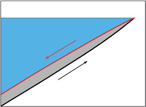
where E is the applied electric field and D is the electric displacement [15]. To measure the stored energy density, discharged energy density (Ud), and charge/discharge efficiency (η) of the dielectrics, the electric displacement (D) is measured as a function of applied electric field (E) during the charging and discharging processes, which is also called as the D-E loop. The schematic of typical D-E loop of the dielectric material is shown in Figure 1.1. The stored energy density can be calculated by integrating the area bounded by the charging curve, the D-axis, and the horizontal line y = Dmax. Similarly, the discharged energy density can be calculated by integrating the area bounded by the discharging curve, the D-axis, and the horizontal line y = Dmax. The energy loss (Ul) during the charge/discharge circle can be represented by the area bounded by the charging and discharging curves. Apparently, the stored energy density equals to the discharged energy density plus the energy loss, that is, Us = Ud + Ul. The charge/discharge efficiency is defined as η = Ud/Us × 100%. For linear dielectrics, the electric displacement increases linearly with the applied electric field, i.e. D = ε0εrE, where ε0 is the vacuum dielectric constant (8.85 × 10⁻¹² F/m) and εr is the relative dielectric constant of the dielectric material [16–18]. As a result, the stored energy density of linear dielectrics can be simplified as
It is suggested from Eqs. (1.1) and (1.2) that the energy density of dielectric materials can be improved by increasing at least one of the two parameters, i.e. the dielectric constant (εr) and the electrical breakdown strength (Eb). This is because the dielectric constant determines the electric displacement, while the electrical breakdown strength determines the maximum electric field that can be applied on the dielectric material. For polymer dielectric materials, the dielectric constant is relatively lower than their ceramic counterparts [19–21], so inorganic nanofillers with high dielectric constant are introduced to
Figure 1.1 Schematic of typical D-E loop of dielectric materials.
improve the dielectric constant of polymer dielectrics. In terms of improving the breakdown strength, highly insulated nanofillers are incorporated into the polymer dielectrics.
For capacitive energy storage in dielectric materials, the stored energy density cannot be fully discharged at the removal of the applied electric field because of various energy losses, such as polarization loss, conduction loss, and hysteresis loss [22]. In most cases, the energy loss would be converted into waste heat, which accelerates the dielectric aging and even causes thermal runaway of the dielectric materials [23, 24]. Therefore, the charge/discharge efficiency is another key parameter for dielectric materials. Since the energy loss is converted into waste heat, which is harmful to the operation of dielectric materials, it is more meaningful to concurrently improve the energy density and the charge/discharge efficiency of the dielectric materials, rather than simply increasing the energy density. In order to increase the charge/discharge efficiency, the energy loss, especially conduction loss under high electric field, should be suppressed. To achieve the inhibition of conduction loss, some highly insulated nanofillers have been introduced into the polymer dielectrics.
Simultaneous enhancement of dielectric constant and breakdown strength is highly desired in the development of high performance polymer composites for electrical energy storage. However, in most cases, the increase in dielectric constant would result in the decrease of breakdown strength, which restricts the improvement of the energy density. So achieving high dielectric constant while maintaining high breakdown strength is still a great challenge. Because of the large mismatch of the electrical parameters between the inorganic nanofillers and polymer matrix, the electric field at the nanofiller/polymer interface is greatly enhanced, which results in the reduced breakdown strength. Moreover, the dispersion of inorganic nanofillers into polymer matrix is always a challenge in the development of polymer composites because of the high surface energy of nanofillers and the different surface physical and chemical properties between the nanofillers and polymer matrix. As a result, nanofiller aggregation is observed in polymer composites. The aggregation of nanofillers would introduce numerous defects in the polymer matrix, which would decrease the electrical breakdown strength and increase the conduction loss. To address these issues, various strategies have been proposed to develop high performance polymer composites for electrical energy storage, including controlling the nanofiller dimension and morphology, controlling the nanofiller distribution and orientation, modifying the nanofiller/polymer interface, introducing multiple nanofillers, and constructing multilayered composites.
1.3 Effect of Nanofiller Dimension
To increase the capacitive energy storage performance of the polymer composites, various inorganic nanofillers have been used to utilize the interfacial polarization and the high dielectric constant of the nanofillers, as well as the inhibition of conduction loss and electrical breakdown. Nanofillers with high dielectric constant, such as titanium oxide (TiO2), barium titanate (BaTiO3, BT), strontium titanate (SrTiO3), barium strontium titanate (BaxSr1 xTiO3, BST), lead zirconate titanate (PbZrxTi1 xO3, PZT), and calcium copper titanate (CaCu3Ti4O12, CCTO), have been used to improve the dielectric constant and
energy density of the polymer composites [25–30]. Moreover, nanofillers with moderate dielectric constant but highly insulating performance, such as magnesium oxide (MgO), aluminum oxide (Al2O3), and silicon oxide (SiO2), have been used to enhance the breakdown strength and suppress the conduction loss [31–33].
The dimension of the nanofillers can significantly influence the performance of the polymer composites. There are mainly three categories of the nanofillers: 0D fillers, 1D fillers, and 2D fillers. 0D fillers have nanoscale dimensions in all three directions, such as spherical nanoparticles. 1D fillers have nanoscale dimensions in two directions, such as nanowires and nanofibers. 2D fillers have nanoscale dimension in only one direction, such as nanoplates and nanosheets.
Compared with 0D nanofillers, 1D nanofillers are more efficient to increase the dielectric constant of polymer composites at relatively low nanoparticle content because of the lower percolation threshold of the high-aspect-ratio 1D nanofillers compared with 0D nanofillers [34]. For example, Tang et al. showed that the use of high-aspect-ratio BT nanowires can enhance the dielectric constant of poly(vinylidene fluoridetrifluoroethylene-chlorofluoroethylene) [P(VDF-TrFE- CFE)] terpolymer more efficiently than the BT nanoparticles [35]. The dielectric constant of P(VDF-TrFE- CFE)/BT nanowire composite can reach up to 69.5 at 17.5 vol% of BT nanowires, while the dielectric constant of P(VDF-TrFE- CFE)/BT nanoparticle composite is only around 52 at 30 vol% of BT nanoparticles. As the result of enhanced dielectric constant, the P(VDF-TrFE- CFE)/BT nanowire composites exhibit a high discharged energy density of 10.48 J/cm3, which is 45.3% higher compared with that of the P(VDF-TrFE- CFE) terpolymer of 7.21 J/cm3.
Shen et al. compared the electrical breakdown propagation in poly(vinylidene fluoride) (PVDF)/BT nanoparticle and PVDF/BT nanofiber composites based on the phase-field simulation [36]. As shown in Figure 1.2, the breakdown phase grows from the nucleation within the composites when the electric field increases beyond the threshold (i.e. 165 kV/mm). In the PVDF/BT nanoparticle composite, the breakdown phase tends to grow at the vulnerable filler/polymer interface and then passes through the fillers near the breakdown path. While in the PVDF/BT nanofiber composite, the breakdown phase propagation is rather different. It is found that the breakdown phase in the nanofiber-based composite tends to penetrate through the nanofibers until the electric field reaches a higher threshold. As a result, the nanofiber-based composite exhibits higher electrical breakdown strength compared with the nanoparticle-based composite. The quantitative breakdown phase growth behavior indicates that the breakdown phase starts to increase when the electric field reaches 140 kV/mm. Compared with nanofiber-based composite, nanoparticle-based composite shows a higher increase rate of the breakdown phase. The breakdown phase in the nanoparticle-based composite gets saturated when the electric field approaches 200 kV/mm, indicating that the nanoparticle-based composite is totally breakdown. In stark contrast, the nanofiber-based composite gets totally breakdown when the electric field reaches 225 kV/mm. The difference in the electrical breakdown behavior comes from the different electric field distribution. The electric field in the nanoparticle-based composite concentrates at the two shoulders along the electric field direction. In the nanofiber-based composite, the electric field concentrates at the vertices of the nanofibers. So the breakdown phase is easier to get through the nanoparticles. Therefore, the nanoparticle-based composite exhibits lower breakdown strength.

Figure 1.2 The breakdown phase propagation simulation based on phase field model in composites filled with 10 vol% of (a, b) BT nanoparticles and (c, d) BT nanofibers, (e) the evolution of breakdown phase under applied electric field. Insets in (e) show the electric field distribution in corresponding polymer composites. Source: Shen et al. [36]. Reproduced with permission of John Wiley & Sons.
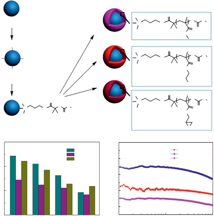
Compared with 0D and 1D nanofillers, 2D nanofillers can impede the charge carrier transport and thus suppress the conduction loss because of the special lamellar structure [37–40]. Moreover, the 2D nanofillers can substantially improve the electrical breakdown strength of the polymer composites. Zhu et al. compared the electrical and capacitive energy storage performance of PVDF/TiO2 composites filled with 5 wt% of 0D, 1D, and 2D TiO2 nanofillers [41]. It is found that the 2D TiO2 nanofillers can not only increase the
1 Polymer Composites for Electrical Energy Storage
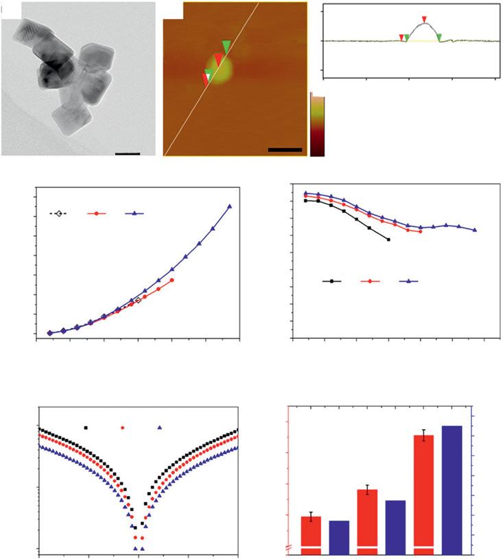
dielectric constant but also suppress the dielectric loss, which is desirable for electrical energy storage application (Figure 1.3). Because the 2D TiO2 nanofillers can effectively suppress the charge carrier transport, the leakage current of the composite with 2D TiO2 nanofillers is only a half of that of the composite with 0D TiO2 nanofillers. The composite with 2D TiO2 nanofillers also exhibits higher electrical breakdown strength (i.e. 566 MV/m) in comparison to that of the composite with 0D (i.e. 295 MV/m) and 1D (i.e. 382 MV/m)
Figure 1.3 (a) TEM image of 2D TiO2 nanofillers, (b) atomic force microscopy (AFM) image of 2D TiO2 nanofillers and corresponding surface morphology of the selected line, (c) discharged energy density, (d) charge/discharge efficiency, (e) leakage current density, and (f) electrical breakdown strength of the PVDF/TiO2 composites with 5 wt% of 0D, 1D, and 2D TiO2 nanofillers. Source: Zhu et al. [41]. Reproduced with permission of American Chemical Society.
TiO2 nanofillers, representing an increase of 92 and 48%, respectively. As the result of increased breakdown strength and dielectric constant, as well as the suppressed conduction loss, the composite with 2D TiO2 nanofillers shows the highest discharged energy density of 13 J/cm3 at 570 MV/m, which is about 236 and 382% that of the composite with 0D (i.e. 5.5 J/cm3 at 400 MV/m) and 1D (i.e. 3.4 J/cm3 at 300 MV/m) TiO2 nanofillers, respectively. Moreover, the charge/discharge efficiency of the composite with 2D TiO2 nanofillers is also the highest among the three kinds of composites because of the suppressed conduction loss.
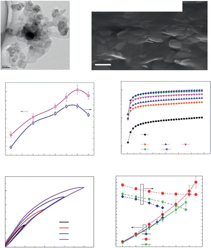
Apart from the 2D nanofillers with high dielectric constant, such as TiO2 nanoplates, 2D nanofillers with high insulating performance, such as hexagonal boron nitride nanosheets (BNNSs), aluminum oxide (Al2O3) nanoplates, and montmorillonite (MMT) nanosheets, have been widely used in polymer composites for electrical energy storage because of their unique ability to improve the breakdown strength of the polymer composites [42–44]. For example, owing to the wide bandgap (~6 eV) and excellent breakdown strength (~800 MV/m) of BNNS, the P(VDF-TrFE- CFE)/BNNS composite can reach up to a high electrical breakdown strength of 610 MV/m at the BNNS filler content of 12 wt% (Figure 1.4), which represents an enhancement of 70% as compared with that of the pristine P(VDF-TrFE- CFE) polymer of 362 MV/m [23]. Moreover, the P(VDF-TrFE- CFE)/BNNS composite shows an order of magnitude improvement in the high-field electrical resistivity over the pristine polymer. These results indicate that the highly insulated 2D nanofillers can function as an efficient barrier layer to impede the electrical conduction and breakdown. Because of the increased breakdown strength and electrical resistivity, the P(VDF-TrFE- CFE)/BNNS composite shows a maximum discharged energy density of 20.3 J/cm3, which is 121% over that of the P(VDF-TrFE- CFE) polymer, i.e. 9.3 J/cm3. In addition to the enhanced discharged energy density, the charge/discharge efficiency of P(VDF-TrFE- CFE)/BNNS composite is also significantly enhanced, i.e. 83% at 300 MV/m and 80% at 600 MV/m.
1.4 Orientation of Nanofillers
Considering the superiority of high-aspect-ratio nanofillers over 0D nanofillers, constructing anisotropic dielectric polymer composites with aligned nanofillers can fully utilize the high-aspect-ratio nanofillers to tailor the dielectric properties and electrical energy storage performance of the polymer composites. For example, it is shown that when the 1D nanofillers are aligned in parallel to the electric field direction, the enhancement of the dielectric constant is more obvious. While for increasing the electrical breakdown strength, nanofillers aligned perpendicular to the electric field direction are more effective [3]. These phenomena are closely related to the morphology of the nanofillers and the electric field distribution in the polymer composites. Considering that 2D nanofillers are usually used to increase the electrical breakdown strength of the polymer composites, it is obvious that the perpendicularly aligned 2D nanofillers are more effective to impede the charge transport and electrical breakdown propagation.
Using the high-throughput phase-field simulation, Shen et al. demonstrated the effect of 1D and 2D nanofiller alignment on the electrical breakdown strength of the polymer composites filled with 10 vol% nanofillers [36]. The breakdown phase growth is substantially
Solution-cast P(VDF-TrFE-CFE)
P(VDF-TrFE-CFE)/BNNSs Melt-stretched P(VDF-TrFE-CFE)
Figure 1.4 (a) TEM image of BNNSs, (b) cross-section scanning electron microscopy (SEM) image of the P(VDF-TrFE-CFE)/BNNS composite, (c) Weibull breakdown strength and shape parameter as functions of BNNS fraction, (d) electrical resistivity of P(VDF-TrFE-CFE)/BNNS composite with different contents of BNNSs under 10 MV/m, (e) D-E loops of P(VDF-TrFE-CFE)/BNNS composite with 12 wt% of BNNSs, and (f ) discharged energy density and charge/discharge efficiency of pristine P(VDF-TrFE-CFE) and P(VDF-TrFE-CFE)/BNNS composite with 12 wt% of BNNSs.
Source: Li et al. [23]. Reproduced with permission of The Royal Society of Chemistry.
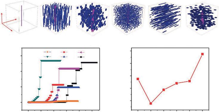
different in the polymer composites with different nanofiller morphologies and their alignment (Figure 1.5). The polymer composite with vertically aligned nanofibers shows the lowest breakdown strength owing to the condensed electric field distribution that promotes the growth of the breakdown phase. Among the five simulated structures, only the polymer
Figure 1.5 3D simulations of microstructure effects on breakdown, (a) breakdown phase morphology in the nanocomposites with different microstructures; (b) evolutions of the breakdown phase volume fraction under applied electric fields; (c) extracted breakdown strengths for corresponding nanocomposites. Source: Shen et al. [36]. Reproduced with permission of John Wiley & Sons.
composite with parallel nanosheets exhibits the higher electrical breakdown strength than that of the pure polymer because of the dispersed electric field. These results indicate that the volume fraction of the nanofillers should not be higher than 10 vol% where high electrical breakdown strength is desired.
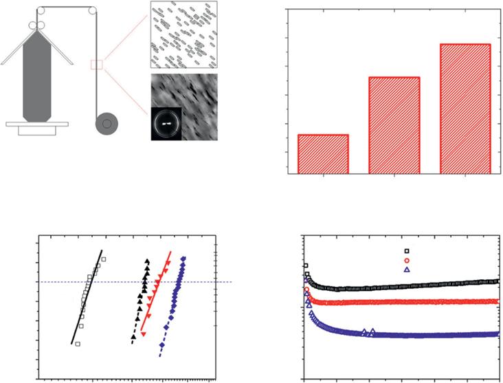
Various material processing methods have been proposed to align the nanofillers in polymer composites, including dielectrophoresis, film stretching assembly, electrospinning, template-assisted fabrication, using nanorod array, and freeze casting [45–50]. Li et al. prepared polymer composites with 2D MMT nanofillers aligned in the polyethylene (PE) matrix by film blowing [51]. The film blowing process can effectively align the 2D MMT nanofillers parallel to the film surface, and the orientation degree of the nanofillers can be readily controlled by changing the shear rate of the film blowing (Figure 1.6). By changing the shear rate, three PE/MMT composites with different MMT nanofiller orientation factors are obtained. The orientation of the MMT nanofillers is observed by transmission electron microscopy (TEM) and further quantified by two-dimensional wide angle X-ray diffraction (WAXD). The orientation factors for the three composites are 0.70, 0.78, and 0.83, respectively. It is shown that the electrical breakdown strength of the PE/MMT composites significantly increases with the orientation of the 2D MMT nanofillers. The electrical breakdown strength for the composites with low, medium, and high filler orientation factors are 440, 490, and 560 MV/m, respectively, which is substantially higher than that of the pristine PE polymer of 300 MV/m. The oriented 2D MMT nanofillers can act as barriers to add the tortuosity of the electrical breakdown pathway and thus impede the propagation of electrical breakdown. The orientation of the 2D MMT
Blown film extrusion:
Figure 1.6 (a) Schematic of film blowing process to align the MMT nanofillers along the flow direction, with MMT surface parallel to film surface; (b) orientation factor of the MMT nanofillers in the composite films prepared by different shear rate in film blowing; (c) Weibull distribution and characteristic dielectric breakdown strength; and (d) electrical conductivity under 55 MV/m for the composite films with different MMT nanofiller orientation factor. Source: Li et al. [51]. Reproduced with permission of American Chemical Society.
nanofillers is also beneficial to suppress the conduction current and increase the electrical resistivity of the polymer composites. The electrical resistivity of the composite with the highly oriented MMT is four times higher than that of the composite with the lowest filler orientation factor.
Xie et al. proposed a physical-assisted casting method to fabricate the P(VDF- CTFE)/BT nanowire composites with the BT nanowires aligned in the Z direction and X–Y direction [52]. The Z-aligned nanowires are more efficient in improving the dielectric constant of the polymer composites. However, the composite with Z-aligned nanowires shows the lowest electrical breakdown strength. In the Z-aligned composite, the nanowires are aligned parallel to the direction of the applied electric field, so the inter-filler distance is relatively small, which makes the breakdown channels traveling along the nanowires at relatively low electric field. Whereas, the X–Y aligned nanowires can act as barriers for the high-energy charge carriers, which increase the electrical breakdown strength of the polymer composites.