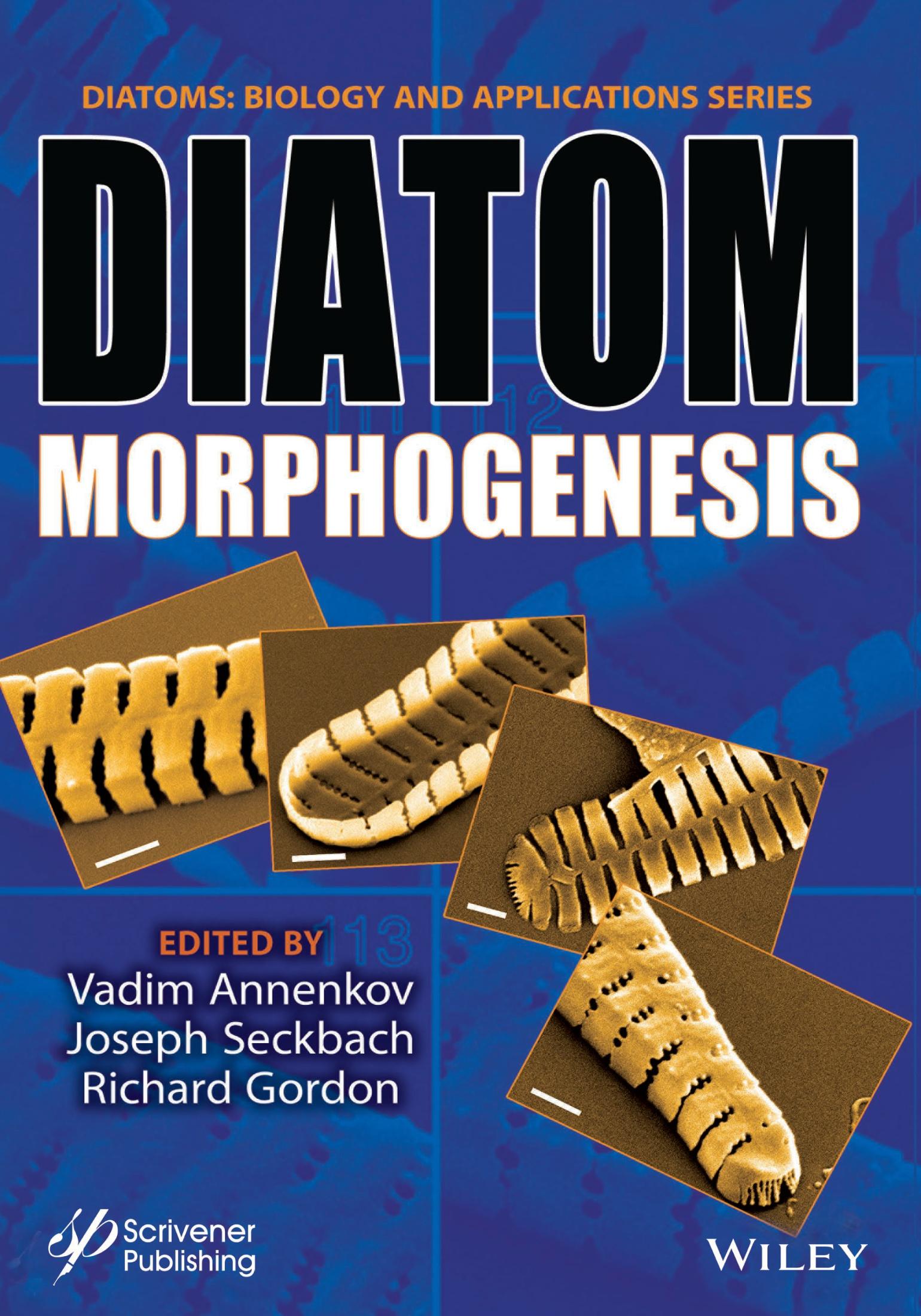
Diatom Morphogenesis
Edited by Vadim Annenkov,
Limnological Institute, Siberian Branch of Russian Academy of Sciences
Joseph Seckback
The Hebrew University of Jerusalem, Israel and
Richard Gordon
Gulf Specimen Marine Laboratory & Aquarium, Panacea, FL, USA and Wayne State University, Detroit, MI, USA
This edition first published 2022 by John Wiley & Sons, Inc., 111 River Street, Hoboken, NJ 07030, USA and Scrivener Publishing LLC, 100 Cummings Center, Suite 541J, Beverly, MA 01915, USA © 2022 Scrivener Publishing LLC
For more information about Scrivener publications please visit www.scrivenerpublishing.com.
All rights reserved. No part of this publication may be reproduced, stored in a retrieval system, or transmitted, in any form or by any means, electronic, mechanical, photocopying, recording, or otherwise, except as permitted by law. Advice on how to obtain permission to reuse material from this title is available at http://www.wiley.com/go/permissions.
Wiley Global Headquarters
111 River Street, Hoboken, NJ 07030, USA
For details of our global editorial offices, customer services, and more information about Wiley products visit us at www. wiley.com.
Limit of Liability/Disclaimer of Warranty
While the publisher and authors have used their best efforts in preparing this work, they make no representations or warranties with respect to the accuracy or completeness of the contents of this work and specifically disclaim all warranties, including without limitation any implied warranties of merchant-ability or fitness for a particular purpose. No warranty may be created or extended by sales representatives, written sales materials, or promotional statements for this work. The fact that an organization, website, or product is referred to in this work as a citation and/or potential source of further information does not mean that the publisher and authors endorse the information or services the organization, website, or product may provide or recommendations it may make. This work is sold with the understanding that the publisher is not engaged in rendering professional services. The advice and strategies contained herein may not be suitable for your situation. You should consult with a specialist where appropriate. Neither the publisher nor authors shall be liable for any loss of profit or any other commercial damages, including but not limited to special, incidental, consequential, or other damages. Further, readers should be aware that websites listed in this work may have changed or disappeared between when this work was written and when it is read.
Library of Congress Cataloging-in-Publication Data
ISBN 978-1-119-487951
Cover image: Colored scanning electron micrographs (SEMs) of a morphogenetic sequence of the diatom Fragillaria capucina var. mesolepta by Dr. Mary Ann Tiffany, Biology Department, San Diego State University, USA Sample taken from Lake Murray (a freshwater San Diego Reservoir) on 3/18/2000.
Cover design by Russell Richardson
Set in size of 11pt and Minion Pro by Manila Typesetting Company, Makati, Philippines
2.2.8
3.3
5 Geometric Models of Concentric and Spiral Areola Patterns of Centric Diatoms
Anton M. Lyakh
5.1 Introduction
5.2 Set of Common Rules Used in the Models
5.3 Concentric Pattern of Areolae
5.4 Spiral Patterns of Areolae
5.4.1 Unidirectional Spiral Pattern
5.4.2 Bidirectional Spiral Pattern
5.4.3 Common Genesis of Unidirectional and Bidirectional Spiral Patterns
5.5 Conversion of an Areolae-Based Model Into a Frame-Based Model
5.6 Conclusion
6 Diatom Pore Arrays’ Periodicities and Symmetries in the Euclidean Plane: Nature Between Perfection and Imperfection
Mohamed M. Ghobara, Mary Ann Tiffany, Richard Gordon and Louisa Reissig
6.1 Introduction
6.2 Materials and Methods
6.2.1
6.2.2 Two-Dimensional Fast Fourier Analysis and Autocorrelation Function Analysis
6.2.3
6.2.4 Accuracy of 2D ACF-Based Calculations
6.2.5 The Perfection of the Unit Cell Parameters Between Different Parts (Groups of Pore Arrays) of the Same Valve and the Same Micrograph
6.3 Results and Discussion
6.3.1 Toward Standardization of the Methodology for the Recognition of 2D Periodicities of Pore Arrays in Diatom Micrographs 126
6.3.1.1 Using Two-Dimensional Fast Fourier Transform Analysis 126
6.3.1.2 Using Two-Dimensional Autocorrelation Function 131
6.3.1.3 The Accuracy of Lattice Parameters’ Measurements Using the Proposed 2D ACF Analysis 134
6.3.2 Exploring the Periodicity in Our Studied Micrographs and the Possible Presence of Different Types of 2D Lattices in Diatoms 137
6.3.2.1 Irregular Pore Scattering (Non-Periodic Pores) 137
6.3.2.2 Linear Periodicity of Pores in Striae (1D Periodicity) 138
6.3.2.3 The Different 2D Lattices in Diatom Pore Arrays 140
6.3.3 How Perfectly Can Diatoms Build Their 2D Pore Arrays? 146
6.3.3.1 Variation of the 2D Lattice Within the Connected Pore Array of the Valve 146
6.3.3.2 Comparison of 2D Lattice Parameters and Degree of Perfection of Distinct Pore Array Groups in the Same Micrograph and Valve but With Different Rotational or Reflection Symmetry 148
6.3.3.3 The Perfection of 2D Lattices of Diatom Pore Arrays Compared to Perfect (Non-Oblique) 2D Bravais Lattices 148
6.3.4 Planar Symmetry Groups to Describe the Whole Diatom Valve Symmetries and Additionally Describe the Complicated 2D Periodic Pore Arrays’ Symmetries
7 Quantified Ensemble 3D Surface Features Modeled as a Window on Centric Diatom Valve Morphogenesis
Janice L. Pappas
7.1 Introduction
7.1.1
7.1.2
7.1.3
7.1.4 3D Surface Feature Geometry and Morphological Attributes
7.1.5 Centric Diatom Taxa Used as Exemplars in 3D Surface Models for Morphogenetic Analysis
7.1.6 Morphogenetic Descriptors of Centric Diatoms in Valve Formation as Sequential Change in 3D Surface Morphology
7.1.7 Purposes of This Study
7.2 Methods
7.2.1 Measurement of Ensemble Surface Features and 3D Surface Morphology: Derivation and Solution of the Jacobian, Hessian, Laplacian, and Christoffel Symbols 168
7.2.1.1 The Jacobian of 3D Surface Morphology
7.2.1.2
7.2.1.3 First and Second Fundamental Forms and Surface Characterization of the Monge Patch 169
7.2.1.4 3D Surface Characterization via Gauss and Weingarten Maps and the Fundamental Forms 170
7.2.1.5 Peaks, Valleys, and Saddles of Surface Morphology and the Hessian 170
7.2.1.6 Smoothness as a Characterization of Surface Morphology and the Laplacian 171
7.2.1.7 Point Connections of 3D Surface Morphology and Christoffel Symbols 171
7.2.1.8 Protocol for Using Centric Diatom 3D Surface Models and Their Ensemble Surface Features in
7.4.1 Ensemble Surface Features and Physical Characteristics of
7.4.2 Factors Affecting
7.4.3 Diatom Growth Patterns—Buckling and Wave Fronts
7.4.4 Valve Formation, Ensemble Surface Features, and Self-Similarity
7.4.5 Diatom Morphogenesis: Cytoplasmic Inheritance and Phenotypic Plasticity
7.4.6 Phenotypic Variation and Ensemble Surface Features:
8 Buckling: A Geometric and Biophysical Multiscale Feature of Centric Diatom Valve Morphogenesis
Janice L. Pappas and Richard Gordon
8.1 Introduction
8.2
8.3 Background: Multiscale Diatom Morphogenesis
8.3.1 Valve Morphogenesis—Schemata of Schmid and Volcani and of Hildebrand, Lerch, and Shrestha
8.3.2 Valve Formation—An Overview at the Microscale
8.3.3 Valve Formation—An Overview at the Meso- and Microscale
8.3.4 Valve Formation—An Overview at the Meso- and Nanoscale
8.4 Biophysics of Diatom Valve Formation and Buckling 201
8.4.1 Buckling as a Multiscale Measure of Valve Formation
8.4.2 Valve Formation—Cytoplasmic Features and Buckling 202
8.4.3 Buckling: Microtubule Filaments and Bundles 203
8.4.4 Buckling: Actin Filament Ring 204
8.5 Geometrical and Biophysical Aspects of Buckling and Valve Formation 205
8.5.1 Buckling: Geometry of Valve Formation as a Multiscale Wave Front 205
8.5.2 Buckling: Valve Formation and Hamiltonian Biophysics 207
8.5.3 Buckling: Valve Formation and Deformation Gradients 208
8.5.4 Buckling: Multiscale Measurement With Respect to Valve Formation 210
8.5.5 Buckling: Krylov Methods and Association of Valve Surface Buckling With Microtubule and Actin Buckling 210
8.6 Methods 211
8.6.1 Constructing and Analyzing 3D Valve Surface and 2D Microtubule and Actin Filament Models 211
8.6.2
9 Are Mantle Profiles of Circular Centric Diatoms a Measure of Buckling Forces During
9.2.1
9.3.1
9.4.1
Circular Centric 2D Profiles and 3D Surfaces
11.4.4
Johannes
12.2
12.4 Frustule
13.3
13.5
13.8
13.9
13.10
13.11
16.5
16.5.1
16.5.2
Preface
Diatoms comprise a large, unicellular eukaryotic algal group that thrives mainly in aqueous environments: in fresh water, and in ponds, lakes and oceans. They may be attached to benthic substrates, in moist habitats or in floating debris and on macrophytes, and as phytoplankton; they form a substantial basis of aquatic food webs. They are ubiquitous, being distributed among various ecological locations. Among this group are some extremophiles with varying features, such as living in high temperatures, surviving desiccation, or in ice and at extreme ranges of pH. Some 20%–30% of the oxygen we breath is produced by diatom photosynthesis.
Vegetative cells of diatoms are diploid (2N), and meiosis can take place, producing male and female gametes fusing to zygotes which grow to auxospores.
One of their specific features is that their chemical composition includes siliceous (glassy) cell walls (frustules). Their exoskeleton is made of two halves called “valves” that fit inside one another, secured by silica “girdle bands”.
Diatoms’ fine structure is very impressive as revealed by transmission electron microscope, scanning microscope, and atomic force micrographs. The appearance of their cells is strikingly unique, and their shells are beautiful attractive shapes, with 60,000 to 200,000 species.
Why Valve Morphogenesis is Important?
Because there is so much detail in their silica wall shapes, spanning 8 orders of magnitude, diatoms are model organisms for single-cell morphogenesis. The problem of single cell morphogenesis has a long history, as yet unsolved, and perhaps diatoms rather than desmids and ciliates will now lead the way, especially given their 200 million years fossil record. This may further be because diatoms serve as a source of biofuel, food supplements and lipids and serve as significant material for nanotechnology. Thus, they are of very wide interest.
This volume focuses on the morphogenesis of diatoms, namely, the formation of their shape and the initial developmental steps.
The chapters were contributed by experts on morphological diatoms. The authors stem from the USA, Russia, Denmark, Germany, Greece, Israel, and Portugal.
Introduction for a Tutorial on Diatom Morphology
Kalina Manoylov1* and Mohamed Ghobara2
1Dept. of Biological & Environmental Sciences, Georgia College and State University, Milledgeville, GA, United States
2Department of Physics, Freie Universitat Berlin, Berlin, Germany
Abstract
Diatoms are an exceptionally successful group of unicellular microalgae with a large contribution of global primary production in aquatic environments and contributing a significant amount of oxygen to both hydro- and atmospheres. They are fascinating throughout their life and even after death, thanks to their unique cell walls made from ornamented silica. The diatoms include centric species, which may have radial or polar symmetry, and pennates, which include araphid, monoraphid, and biraphid species. Several applications have utilized diatomite, i.e., the fossil form of diatom frustules. To date, many diatoms’ secrets have been understood; however, there are still more hidden. Thus, there is a need for more research on diatom basic biology and applications. Seeking this goal, more people should be encouraged to work on diatoms. Often novice researchers are overwhelmed by the terminology associated with the diverse morphology, the discrepancy between expected features for published descriptions, and the actual observation of those complex 3D organisms, which can be a barrier for more progress. Here, we provide a brief introduction to the beginners with a guide to approach the complex diatom morphology focusing on the tools that can be used for its study.
Keywords: Diatom morphology, tutorial, LM and SEM, frustule morphology
1.1 Diatoms in Brief
Diatoms are unicellular, eukaryotic, microscopic algae (range from 1.5 µm to 5 mm in length, or diameter [1.9]), which maintain large population numbers and contribute considerably to the carbon and oxygen cycle on a global scale [1.8]. This ecologically successful group of algae is present in all aquatic habitats e.g. [1.1, 1.2] and even extends to humid terrestrial places. In aquatic habitats, diatoms are present in the photic zone, i.e., the region of water that light strongly penetrates, as well as in the benthic zone, i.e., the lowest level of water adjacent to the bottom with dim light conditions, depending on water column height and water’s turbidity. Diatoms can exist as planktonic
*Corresponding author: kalina.manoylov@gcsu.edu
Vadim Annenkov, Joseph Seckback and Richard Gordon (eds.) Diatom Morphogenesis, (3–18) © 2022 Scrivener Publishing LLC
(i.e., suspended in the water column), benthic (i.e., living near the bottom), epiphytic (i.e., adhered to aquatic plants [1.19], Figures 1.2c–d), or epizoic (i.e., adhered to a wide range of marine organisms such as crustaceans, mollusks, and vertebrates [1.19, 1.38]), or epilithic (i.e., attached completely or partially to submerged rocks). The adhesion ability of some diatoms is related to their mucilage secretion from specialized areas within their rigid cell walls (such as examples shown in Figures 1.1d and 1.2c–d). Some diatoms can form colonies in different arrangements such as chains and ribbons (examples shown in Figures 1.1 and 1.2).
Diatoms are a unique group of microalgae for several reasons, but one of the most notable and unique differences is the glass cell walls they possess [1.45]. This cell wall is called the “frustule” and is composed of amorphous hydrated silica that gives it unique properties. In general, the frustule is composed of two pieces that fit together like a petridish, meaning that the lower part of the frustule, called the hypotheca, sits inside of the upper part of the frustule, called the epitheca. The frustule volume extends by adding strips of silica called girdle bands (cingulum) to the mantle, i.e., the curved edge of the valve. It should be noted that there are plenty of frustule morphologies that vary between taxa.
Diatoms reproduce both asexually (visible in Figure 1.6) and sexually. Most of the time, they reproduce asexually via binary fission through adding new hypovalves to the parent valves. Those new hypovalves are synthesized inside the silica deposition vesicle (SDV). Only after the new hypovalves have completely synthesized and the protoplast cleavage, as well as the exocytosis of siliceous parts, has occurred, the final splitting apart will occur, leaving two daughter diatoms in place. Because the SDV forms inside of each new cell
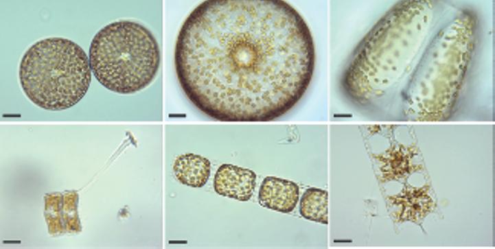
Figure 1.1 Living diatoms as observed under LM, brightfield. (a) Two living cells of Actinoptychus senarius (Ehrenberg) Ehrenberg at the valve view. (b) The valve view of a single living cell of Coscinodiscus wailesii Gran and Angst. (c) The girdle view of a single living cell of Coscinodiscus granii L.F. Gough. (d) Two living cells of Achnanthes brevipes C. Agardh at the girdle view attached to each other with a prolonged stalk for the attachment to the substrate. (e) A living colony of Stephanopyxis turris (Greville) Ralfs with visible linking spines. (f) A living colony of Odontella longicruris (Greville) M.A. Hoban with discoid chloroplasts. Copyright reserved Mary Ann Tiffany, used with her permission. The identification was carried out by Mary Ann Tiffany. All the scale bars are 50 µm.
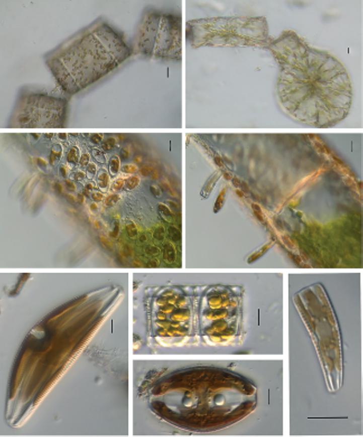
Figure 1.2 Live centric (a, b) and pennate (c–h) diatoms. (a, b) Pleurosira laevis (Ehrenberg) Compère shown from girdle view, frustules with numerous girdle bands in straight filaments with discoid chloroplasts, chains connected with mucilage pads released from ocelli; in (b), visible diameter size restoration within the chain; (c, d) Epiphytic diatoms on Cladophora glomerata (Linnaeus) Kützing, in (c) focus on Cocconeis spp. With visible one flat C-shaped plastid; in (d) focus on Rhoicosphenia spp.; (e) Cymbella sp. partial valve and girdle views, visible chloroplast bridge connecting the chloroplast plates; (f) Eunotia cf. camelus Ehrenberg in girdle view with visible discoid chloroplasts; (g) Amphora ovalis (Kützing) Kützing with H shaped chloroplast; (h) Rhoicosphenia sp. girdle view with visible lobes of the plastid. Scale bars, 10 µm. These micrographs were obtained and identified by KMM.
before splitting into two, each new cell creates a new interior of the petri-dish structure. What this means is that the cell that originally contained the upper part of the petri dish (the epitheca) remains the same size, whereas the cell that originally contained the lower part of the petri-dish (the hypotheca) becomes smaller, since it has now built a smaller hypovalve to fit into it. Repeated cell division, therefore, leads to some part of the resulting
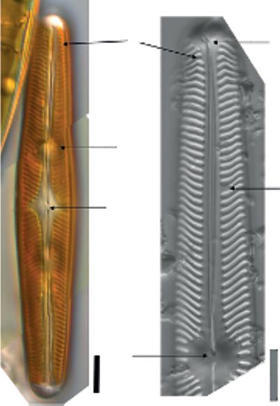
Figure 1.3 Specific diatom morphology gleaned from images with whole and partial valves views of Navicula oblonga (Kützing) Kützing; (a) live linear-lanceolate cell with visible two plates like brown chloroplasts, visible linear striae, and proximal raphe ends deflected slightly toward the secondary side. (b) Valve view after cleaning, axial area is linear, widening toward the central area and about twice the width of the raphe. The central area orbicular. The raphe is lateral, becoming filiform near the proximal ends, which are simple. Central striae do not reach valve edge. These micrographs were obtained and identified by KMM.
Details shown:
1. Central area is more or less orbicular and two to three times wider than the axial area. Proximal raphe ends are simple and barely wider than the raphe. Striae are finely lineate and the individual areolae are difficult to distinguish.
2. Round, subsidiary vacuoles on each side of the nucleus visible behind the glass cell wall and chloroplasts; axial area outlines by lineate striae.
3. Terminal bent striae (terminal striae convergent at the margins and bent back toward the central area). Striae are radiate next to the axial area.
4. Voigt discontinuity identifies the secondary side of the valve morphogenesis. Ontogeny in diatoms varies with morphology; in Naviculoid diatoms, the secondary side shows the completion of silica deposition around the raphe.
5. Distal raphe positioned on the broad, rounded apices and curved toward the primary side of the valve in the opposite direction when compared to the proximal raphe ends. Scale bars, 10 µm.
population becoming smaller and smaller. Were asexual reproduction the only method by which diatoms reproduces, this could lead the population eventually to become vulnerable to dying out, but diatoms are ingenious and have gotten around this problem. At some point, sexual reproduction is initiated by a number of steps, including meiotic divisions to produce male and female gametes. These cells can find each other, fuse to form a zygote and create a structure known as an auxospore, out of which a new large cell of the diatom
species will form, restoring its optimal size, which also depends on the environmental circumstances surrounding the auxospores. Some new research proposes chemical communication with pheromones between the male and female gametes [1.20].
Frustule morphogenesis, deposits SDVs and needs more research with new tools. However, it has been established that the silica morphogenesis of centric species will begin at the center of the valve, and it begins by creating a primary rib in pennate species [1.21]. Completion of the sternum around the raphe slit morphologically can be identified with the Voight discontinuity (Figure 1.3b). From that onset within the mother frustule, the silica will continue to form outward to complete the shape as well as inward to create more layers, with the oldest silica being on the most outside layer [1.46]. The silicic acid (or its anions) is taken from the environment, condensed, associated with proteins synthesized by the endoplasmic reticulum and packaged in a globular vesicle in the Golgi apparatus. Then finally, these vesicles (silica deposition vesicles) are transported by microtubules, likely in a genetically predetermined pattern, and delivered to the new valve interface. These are not the only groups that pull silicic acid (an inorganic compound contains silicon) out of the water and use it to make a frustule, but diatoms do it uniquely.
Diatom frustules are porous with multilayer, multiscalar porosity, a property that is unique for each species, giving frustules their beautiful ornamentation [1.17]. The major bigger pores within the valves are called “areolae” and usually arranged in rows known as “striae”, which could be either branched or not. In the most general way, diatoms can be divided into centric and pennate diatoms, which are classified based on the valve symmetry. Centric diatoms are radially symmetric and lack raphes. Pennate diatoms usually have bilateral symmetry and there can be no, one, or two raphes. Pennate diatoms can further be classified based on variations in the position of the raphe on valve. The raphe is used for motility [1.4] and attachment [1.12]. Sometimes, the frustules are also covered in spines, which can allow some species to hook together and form chains (Figure 1.1e).
The frustule’s morphological features of diatoms are required for identification. Specialized terminology has been collected in [1.5–1.7, 1.15, 1.16], and a general guide to the literature is in [1.10]. Characters continue to be discovered and new descriptive terminologies are proposed [1.23].
1.2 Tools to Explore Diatom Frustule Morphology
The beauty of diatoms was missed until the early, curious microscopists started observing ambiguous glassy microorganisms under their optical microscopes in the 18th century [1.22, 1.38]. Although the light microscope (LM) helped us to reveal the diatoms’ world, diatom frustules also helped the microscopists in developing and testing the quality and resolution of their optical microscopes [1.24, 1.25]. Since the nineteenth century, several works have been published on diatoms, its morphology, and taxonomy by remarkable workers including Kützing, Schmidt, Ehrenberg, Grunow, Hustedt, Krammer, Lange-Bertalot, and more (see references in Round et al. [1.38]). They described both living cells and clean frustules extensively using LM. The unique structure of diatom frustules under LM, with a variety of shapes and symmetries, has captured a wide interest; however, most of the diatom’s real art, at the nanoscale, was kept hidden. The limitations for observing frustule ultrastructure, especially details below 200 nm, were solved after the invention of the electron microscope [1.26].
In 1936, the transmission electron microscope (TEM) was used to capture the first micrograph of a diatom frustule [1.26, 1.27], using it as a test object for the quality and resolution of TEM. After that TEM was used to explore diatom ultrastructure. Following, the scanning electron microscope (SEM) was invented and used extensively as a more effective tool for exploring frustules morphology and ultrastructure [1.24, 1.28, 1.36, 1.38].
The details observed using the SEM and TEM reflected the beauty of diatoms when many hidden details became observable. For instance, some bright striae under an optical microscope appear as arrays of fine pores under the electron microscope (Figure 1.5a). It was, to some extent, a kind of revolution for diatom classification and taxonomy with the morphological details that became available down to 15 nm with SEM and below 10 nm with TEM (Figure 1.5b). Nowadays, the observation of diatom frustule morphology and ultrastructure using LM, SEM, and TEM became routine work for people working on ecology, environment, forensic, nanotechnological, and other applications that concern frustule ultrastructure, monitoring diatom species, and taxonomy.
Although 2D information can be collected from LM and TEM and the 3D-shape appeared under SEM, the information about the surface topology, internal ultrastructure, and siliceous element relationships within diatom frustules was missing. Therefore, more tools were evolved and involved in the exploration and understanding of the 3D complex ultrastructure of the frustule, which could be the reason for their various natural features, including unique photonic, mechanical, and hydrokinetic properties [1.9, 1.45]. The new tools include the atomic force microscope (AFM) and the focused ion beam SEM (FIBSEM) [1.32, 1.34, 1.35, 1.41].
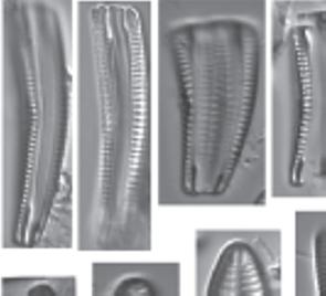
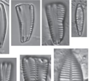
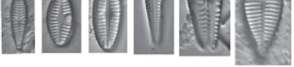
Figure 1.4 Cleaned diatoms in valve (g, h–j, m–r, u, v) and girdle views (a–f, k, l, s, t, w, x). (a–e, g) Rhoicosphenia spp., frustules are clavate and strongly flexed, one valve is concave with long raphe branches and the other valve convex with shortened raphe, different depth pseudosepta visible; (f, k, l) Gomphonema spp. showing valve heterogeneity; (h) Gomphonella olivacea (Hornemann) Raben. (i) Planothidium lanceolatum (Bréb. Ex Kütz.) Lange-Bert, rapheless valve shown with asymmetrical central area containing depression; (j) Geissleria cascadensis (Sovereign) Stancheva and S. A. Spaulding, valves elliptic, with cuneate apices, coarse areolae, three pairs of annulae are present at each apex; (m) Planothidium delicatulum (Kütz.) Round and Bukht. Rapheless valve shown, lacking a central area and two middle striae spaced distantly. (Continued)
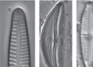
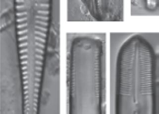
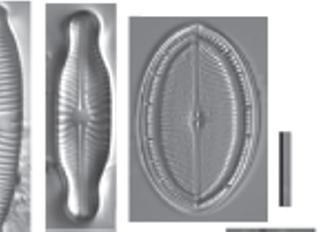
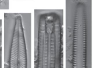
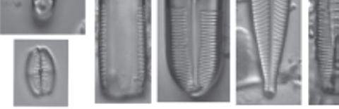
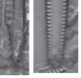
Figure 1.4 (Continued) Cleaned diatoms in valve (g, h–j, m–r, u, v) and girdle views (a–f, k, l, s, t, w, x). (n) Gomphonema sp. valve heteropolar wider in the middle, axial area narrow, central area irregular outlined by two shortened striae and opposite to a single striae finishing with an isolated pore, striae parallel toward the headpole, radiate toward the foot pole; (o) Amphora ovalis, dorsal fascia visible and dorsal striae interrupted transapically by intercostal ribs; (p) Gomphonema micropus Reichardt lanceolate valve with headpole widely drawn out and wider than foot pole, striae radiate, central area unilaterally rectangular with shortened central stria, on the opposite side longer striae finishing with a stigmoid; (q) Navicula genovefae Fusey valve linear-lanceolate with rostrate broadly rounded apices, punctate striae radiate and curved, becoming nearly parallel at the apices, less dense around the well-defined central area; (r) Cocconeis placentula Ehrenb. Valves elliptic, striae radiate and interrupted by a hyaline ring positioned close to the valve margin, siliceous bridges (imbriae extending from valvocopula) visible; (s) Amphora pediculus (Kütz.) Grunow focus from dorsal site of two frustules; (t, u) Caloneis sp. on girdle view striae continue on valve mantle, on the linear valve view with rounded apices, axial area is narrow, broadening to a transverse fascia; (v) Navicula cryptocephala Kütz. Valve lanceolate with protracted apices and visible large, circular central area; (w) Mastogloia pseudosmithii Sylvia S. Lee, E. E. Gaiser, Van de Vijver, Edlund, and S. A. Spaulding, evenly sized partecta (chambers on the valvocopula) on both valves; (x) Navicula cf. tripunctata (O.F. Müll.) Bory. Scale bar, 10 µm. These micrographs were obtained and identified by KMM.
In 1992, the first observation of diatoms using an AFM has been done [1.33]. In general, AFM is used as an advanced tool to explore diatom ultrastructure providing information in the Z-direction, with the ability to understand the surface topology of the frustule parts with a nanoresolution. For instance, AFM observations of Coscinodiscus sp. clean valves revealed a distinct dome topology for the cribellum, which was not observed before [1.34]. At the beginning of the current century, AFM was used in several works for understanding the nanoscale ultrastructure and topology of frustule surfaces in a 3D manner. Today, AFM is also used to explore the organic envelope, micromechanical properties, and to
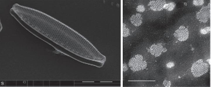
Figure 1.5 (a) SEM of a single cleaned partially open frustule, two overlapping valves, of Nitzschia palea (Kützing) W. Smith, and scale bar is 5 µm. The rows of pores (striae) that observed here cannot be observed under LM for this species. (b) TEM of a close-up in Navicula sp. valve showing the hymenate pore occlusions that will not be observed under SEM; scale bar is 200 nm. These micrographs were obtained and identified by MG.
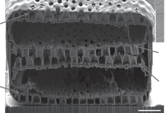
Figure 1.6 A cross-section at the center of Coscinodiscus sp. cell collected and treated while binary fission process was in progress, fabricated and captured by FIB-SEM. Reproduced from Xing et al. [1.42] under a Creative Commons Attribution 4.0 International license.
understand the biomineralization processes of diatom frustules [1.35]. Luís et al. [1.35] can be considered a good review for starting AFM studies on diatom frustules.
Furthermore, diatom valves seem to have a complex inner ultrastructure that cannot be understood completely by observing the internal and external view of a given valve surface using the previously mentioned tools. Although the multilayer, multiscalar porosity can be observed easily using such techniques, the internal anatomy and relations of the siliceous elements of the frustule cannot be understood [1.41]. It was usual to wish that the observation of a broken valve or girdle band at the right site and right angle would help, otherwise, the complex inner structure remained unseen [1.41].
Epivalve of the parent cell
Hypovalve of the parent cell
Thus, another advanced method was required for understanding the inner structures and spatial relationships of the siliceous elements of a given diatom frustule. The FIB-SEM was introduced as a solution for such a problem by cutting the diatom frustule parts at nanoresolution to reveal the inner complex ultrastructure of a given valve or frustule (Figure 1.6) [1.41]. Suzuki et al. [1.40] was the first work introduced using FIB-SEM for making a cross-section in diatoms. Only a few articles are available using FIB-SEM and the field is still growing. The acquired data using FIB-SEM could be used to reconstruct
Table 1.1 A summary of the major tools used to study diatom frustule morphology and its ultrastructure.
The date of first known observation of diatoms using the tool
Anonymous, 1703 [1.22] Krause, 1936 [1.27]
Up-to-date resolution The maximum resolution of the common compound optical microscope can be around 200 nm. Recently, the resolution was enhanced (down to 97 nm) using special kind of lenses [1.37].
When we should use?
Observation of the presence or absence of diatoms in a sample. Identification of diatoms on the genus level. Enumeration of diatom frustules for different purposes.
Up-to-date, the highest TEM resolution could be down to 50 picometer or even lower [1.29].
Mid of 1960s [1.24] Linder et al., 1992 [1.33] Suzuki et al., 2001 [1.40]
The details less than 15 nm was not resolved under most of SEMs. Recently, an outbreak has been achieved, and the resolution of SEM could be below 1 nm [1.39].
Recently, the resolution can be below 1 nm.
Having SEM as the microscope part of the device. Thus, the resolution is dependent on this SEM.
Observation of the fine porosity (mesopores) present in some genera, like raphid pennates (Figure 1.5b).
Observation of thin crosssections in a valve or a girdle band. Observation of the cytoplasmic components of thin crosssections of living cells (living cells anatomy).
Observation of the outer ultrastructure including most porosity. Observation of the overall 3D ultrastructure of the frustule or different parts. Identification at the species and subspecies level.
Observation of the 3D topology of a diatom frustule or its components. Measuring forces related with both living diatoms and its cleaned frustules.
Understanding the inner ultrastructure of diatom frustule or its parts by cutting cross-sections through it.
Observation of the siliceous elements structural relations within the frustule. Observation of the whole 3D ultrastructure of the frustule via the 3D reconstruction. (Continued)
Table 1.1 A summary of the major tools used to study diatom frustule morphology and its ultrastructure. (Continued)
The disadvantages The observations for most of the ultrastructure details will be limited. Either the girdle view or the valve view will be available.
Only the tiniest parts of the valve, like pore occlusions, will be observed. The high energy electron beam may damage some sensitive samples, so it should be used wisely.
The samples must be coated with a conductive layer, which in turn could change the nano texture of the frustule silica and probably pore sizes, thus the thickness and smoothness of the conductive layer should be optimized and be thin as possible without getting nanoparticles on the top.
The high energy electron beam may also damage some sensitive samples The regular resolution keep the pore occlusions of very fine porosity (below 10 nm) hidden.
The frustules must fix to the substrate before measuring.
A very sensitive tool with complicated precautions to follow to get the desired results. This technique sometimes needs more sophisticated preparation of the samples and more sophisticated work to reconstruct the frustule or its parts, however it worth. Related with the presence of the device, which usually is not available for all research groups.
the overall 3D geometry of diatoms to carry out further computational simulations necessary for diatom nanotechnology applications.
Finally, all the techniques mentioned were summarized in Table 1.1 to help beginners and students choose between different tools on-demand.
1.3 Diatom Frustule 3D Reconstruction
Toward the complete understanding of the 3D structure of a given diatom frustule, a comprehensive 3D model can be created from the data collected from different characterization techniques. This approach, which is designated as the 3D reconstruction of diatom frustules, can be used for different purposes but is mainly for computer modeling. Oncoming tools for the 3D reconstruction of diatom frustules are FIB-SEM [1.32, 1.42] and digital holographic microscopy (DHM) combined with SEM [1.30]. The combination of DHM and SEM or AFM might give the ability to model and visualize microscopic 3D objects with a high resolution in all directions [1.30]. Hildebrand et al. [1.32] introduced the ability for the 3D reconstruction of subcellular architecture using FIB-SEM with new insights into the architecture and synthesis process of both the siliceous and organic components inside the