All rights reserved. No part of this publication may be reproduced, stored in a retrieval system, or transmitted, in any form or by any means, electronic, mechanical, photocopying, recording or otherwise, except as permitted by law. Advice on how to obtain permission to reuse material from this title is available at http://www.wiley.com/go/permissions.
The right of Frank Gress, Thomas Savides, Brenna Casey, and Everson L. A. Artifon to be identified as the authors of the editorial material in this work has been asserted in accordance with law.
Registered Offices
John Wiley & Sons, Inc., 111 River Street, Hoboken, NJ 07030, USA
John Wiley & Sons Ltd, The Atrium, Southern Gate, Chichester, West Sussex, PO19 8SQ, UK
Editorial Office
9600 Garsington Road, Oxford, OX4 2DQ, UK
For details of our global editorial offices, customer services, and more information about Wiley products visit us at www.wiley.com.
Wiley also publishes its books in a variety of electronic formats and by print‐on‐demand. Some content that appears in standard print versions of this book may not be available in other formats.
Limit of Liability/Disclaimer of Warranty
The contents of this work are intended to further general scientific research, understanding, and discussion only and are not intended and should not be relied upon as recommending or promoting scientific method, diagnosis, or treatment by physicians for any particular patient. In view of ongoing research, equipment modifications, changes in governmental regulations, and the constant flow of information relating to the use of medicines, equipment, and devices, the reader is urged to review and evaluate the information provided in the package insert or instructions for each medicine, equipment, or device for, among other things, any changes in the instructions or indication of usage and for added warnings and precautions. While the publisher and authors have used their best efforts in preparing this work, they make no representations or warranties with respect to the accuracy or completeness of the contents of this work and specifically disclaim all warranties, including without limitation any implied warranties of merchantability or fitness for a particular purpose. No warranty may be created or extended by sales representatives, written sales materials or promotional statements for this work. The fact that an organization, website, or product is referred to in this work as a citation and/or potential source of further information does not mean that the publisher and authors endorse the information or services the organization, website, or product may provide or recommendations it may make. This work is sold with the understanding that the publisher is not engaged in rendering professional services. The advice and strategies contained herein may not be suitable for your situation. You should consult with a specialist where appropriate. Further, readers should be aware that websites listed in this work may have changed or disappeared between when this work was written and when it is read. Neither the publisher nor authors shall be liable for any loss of profit or any other commercial damages, including but not limited to special, incidental, consequential, or other damages.
Library of Congress Cataloging‐in‐Publication Data
Names: Gress, Frank G., editor. | Savides, Thomas J., editor. | Casey, Brenna, editor. | Artifon, Everson L. A., editor.
Title: Atlas of endoscopic ultrasonography / edited by Frank G. Gress, Thomas John Savides, Brenna Casey, Everson L. A. Artifon.
Description: Second edition. | Hoboken, NJ : Wiley-Blackwell, 2022. | Includes bibliographical references and index.
Identifiers: LCCN 2021015783 (print) | LCCN 2021015784 (ebook) | ISBN 9781119523000 (hardback) | ISBN 9781119523093 (adobe pdf) | ISBN 9781119523031 (epub)
Subjects: MESH: Endoscopy, Digestive System | Digestive System Diseases–diagnostic imaging | Digestive System–diagnostic imaging | Ultrasonography | Atlas
LC record available at https://lccn.loc.gov/2021015783
LC ebook record available at https://lccn.loc.gov/2021015784
Cover Design: Wiley
Cover Images: Courtesy of Dalton Chaves, Courtesy of Anthony Teoh, Courtesy of Cynthia Behling, Courtesy of David L. Diehl, MD, Courtesy of Wilson Kwong, Courtesy of Spencer Cheng, Courtesy of Julio Iglesias Garcia, Courtesy of Toltech
Set in 9/12pt Meridien by Straive, Pondicherry, India 10 9 8 7 6 5 4 3 2 1
Contributors, vii
Preface, xi
About the Companion Website, xii
Part 1 Normal EUS Anatomy, 1
1 Normal Human Anatomy, 3
John C. Deutsch
2 Esophagus: Radial and Linear, 10
James L. Wise and John C. Deutsch
3 Normal Mediastinal Anatomy by EUS and EBUS, 14
Juan Corral, Sebastian Fernandez‐Bussy, and Michael B. Wallace
4 Stomach: Radial and Linear, 19
Joo Ha Hwang
5 Bile Duct: Radial and Linear, 22
Kapil Gupta
6 EUS of the Normal Pancreas, 25
Richard A. Erickson and James T. Sing, Jr.
7 Liver, Spleen, and Kidneys: Radial and Linear, 30
Nalini M. Guda and Marc F. Catalano
8 Anatomy of the Anorectum: Radial and Linear, 33
Christoph F. Dietrich
Part 2 Upper and Lower GI EUS, 37
9 Esophageal Cancer, 39
Armen Eskandari and Syed M. Abbas Fehmi
10 EUS for Achalasia, 46
Michael Chang
11 Malignant Mediastinal Lesions, 49
M. Babitha Reddy, David H. Robbins, and Mohamad A. Eloubeidi
12 Benign Mediastinal Lesions, 51
M. Babitha Reddy, David H. Robbins, and Mohamad A. Eloubeidi
13 Gastric Cancer, 53
Douglas O. Faigel and Sarah A. Rodriguez
14 Gastric and Esophageal Subepithelial Masses, 58
Muhammad Tahir and Andrew J. Bain
15 Anorectal Neoplasia, 67
Manoop S. Bhutani and Everson L.A. Artifon
16 Anal Sphincter Disease: Fecal Incontinence and Fistulas, 72
Raymond S. Tang and Thomas J. Savides
17 Endometriosis, 78
José Celso Ardengh, Juan Pablo Román Serrano, Samuel Galante Romanini, Juliana Silveira Lima de Castro, and Isabela Trindade Torres
University of California San Diego La Jolla, CA, USA
Suresh T. Chari, MD
MD Anderson Cancer Hospital
Houston, TX, USA
Dalton Marques Chaves
Gastrointestinal Endoscopy Unit
University of Sao Paulo
Sao Paulo-Brazil
Filipe Tomishige Chaves
Gastrointestinal Endoscopy Unit
University of Sao Paulo Sao Paulo-Brazil
Antonio R. Cheesman, MD
Division of Gastroenterology
Icahn School of Medicine at Mount Sinai
New York, NY, USA
Spencer Cheng, MD, phD
Department of Gastroenterology
Gastrointestinal Endoscopy Unit
University of São Paulo
São Paulo, Brazil
Juan Corral, MD
Division of Gastroenterology and Hepatology
Mayo Clinic College of Medicine Jacksonville, FL, USA
Juliana Silveira Lima de Castro, MD
Staff of Endoscopy Service
Hospital Nove de Julho Sao Paulo, Brazil
Daniel de la Iglesia‐García, MD
Department of Gastroenterology and Hepatology
Health Research Institute
University Hospital of Santiago de Compostela Santiago de Compostela, Spain
John C. Deutsch, MD
Essentia Health Care Systems
Duluth, MN, USA
John M. DeWitt, MD, FACG, FACp, FASGE
Associate Professor of Medicine
Co‐Director, Endoscopic Ultrasound Clinical Program
Division of Gastroenterology and Hepatology
Indiana University Medical Center Indianapolis, IN, USA
J. Enrique Dominguez‐Muñoz,
MD, pHD
Department of Gastroenterology and Hepatology
Health Research Institute
University Hospital of Santiago de Compostela Santiago de Compostela, Spain
Vinay Dhir, MD, DNB
Director Clinical Research and Chief of Endosonography
Institute of Advanced Endoscopy Mumbai, India
David L. Diehl, MD, FASGE Professor of Medicine
Geisinger Medical Center and Geisinger Commonwealth School of Medicine Danville, PA, USA
Christoph F. Dietrich, MD
Professor, Second Department of Internal Medicine
Caritas‐Krankenhaus
Bad Mergentheim, Germany
Christopher J. DiMaio, MD
Director of Therapeutic Endoscopy
Icahn School of Medicine at Mount Sinai
New York, NY, USA
Mohamad A. Eloubeidi, MD, MhS, FASGE, FACp, FACG, AGAF
Professor of Medicine
American University of Beirut School of Medicine Beirut, Lebanon
Richard A. Erickson, MD, FACp, FACG, AGAF
Director, Division of Gastroenterology
Scott and White Clinic and Hospital Professor of Medicine
Texas A&M Health Science Center Temple, TX, USA
Armen Eskandari, MD
Division of Gastroenterology and Hepatology
University of California San Diego La Jolla, CA, USA
Douglas O. Faigel, MD, FACG, FASGE, AGAF
Professor of Medicine
Mayo Clinic College of Medicine Scottsdale, AZ, USA
Syed M. Abbas Fehmi, MD
Clinical Assistant Professor of Medicine
Division of Gastroenterology and Hepatology
University of California San Diego La Jolla, CA, USA
M. Phillip Fejleh, MD
Division of Gastroenterology
University of California San Diego Health Sciences La Jolla, CA, USA
Sebastian Fernandez‐Bussy, MD
Division of Pulmonary Medicine and Critical Care Mayo Clinic College of Medicine Jacksonville, FL, USA
David G. Forcione, MD
Associate Director of Interventional Endoscopy
Massachusetts General Hospital
Harvard Medical School Boston, MA, USA
Larissa Fujii‐Lau, MD
University of Hawaii Honolulu, HI, USA
Carlos K. Furuya JR., pHD, MD
Assistant Professor of Medicine
Department of Gastroenterology
Gastrointestinal Endoscopy Unit
University of São Paulo
São Paulo, Brazil
Mohamed Gasmi, MD
Digestive endoscopy and gastroenterology
department
North Hospital, Marseille, France
Jean‐Michel Gonzalez, MD, phD
Head of Endoscopy Unit
Digestive endoscopy and gastroenterology
department
North Hospital, Marseille, France
Adam J. Goodman, MD
Associate Professor of Medicine
NYU Langone Health
New York, NY, USA
Frank G. Gress, MD, MBA
Department of Medicine
Division of Gastroenterology and Hepatology
Icahn School of Medicine at Mount
Sinai and Mount Sinai South Nassau Hospital Oceanside, NY, USA
Nalini M. Guda, MD, FASGE
Clinical Associate Professor of Medicine
University of Wisconsin, School of Medicine and Public Health
Pancreatobiliary Services
St. Luke’s Medical Center Milwaukee, WI, USA
Kapil Gupta, MD, Mph
Associate Director, Pancreatic and Biliary Diseases
Interventional Endoscopy
Division of Gastroenterology
Cedars‐Sinai Medical Center Los Angeles, CA, USA
Rintaro Hashimoto, MD, pHD
Department of Gastroenterology
University of California Irvine, CA, USA
Sammy Ho, MD
Assistant Professor of Medicine
Director of Pancreaticobiliary Services and Endoscopic Ultrasound
Division of Gastroenterology
Montefiore Medical Center/AECOM Bronx, NY, USA
Joo Ha Hwang, MD, pHD
Stanford University Palo Alto, CA, USA
Edson Ide, pHD, MD
Department of Gastroenterology
Gastrointestinal Endoscopy Unit
University of São Paulo São Paulo, Brazil
viii
Julio Iglesias‐Garcia, MD, pHD
Department of Gastroenterology and Hepatology
Health Research Institute
University Hospital of Santiago de Compostela Santiago de Compostela, Spain
Ann Marie Joyce, MD
Assistant Professor of Medicine
Tufts University School of Medicine Burlington, MA, USA
Michel Kahaleh, MD, AGAF, FACG, FASGE
Distinguished Professor of Medicine
Clinical Director of Gastroenterology Chief of Endoscopy
Director Pancreas Program
Rutgers Robert Wood Johnson Medical School New Brunswick, NJ, USA
Masayuki Kitano, MD, pHD
Second Department of Internal Medicine Wakayama Medical University Wakayama, Japan
Kumar Krishnan, MD
Interventional Endoscopy
Harvard Medical School
Massachusetts General Hospital Boston, MA, USA
Wilson T. Kwong, MD, MS
Assistant Professor of Medicine
Division of Gastroenterology
University of California San Diego Health Sciences La Jolla, CA, USA
Sandeep Lakhtakia, MD, MNAMS, DM
Consultant
Asian Institute of Gastroenterology Hyderabad, India
Alberto Larghi, MD, pHD
Digestive Endoscopy Unit
Fondazione Policlinico A. Gemelli IRCCS Rome, Italy
Jose Lariño‐Noia, MD
Department of Gastroenterology and Hepatology
Health Research Institute
University Hospital of Santiago de Compostela Santiago de Compostela, Spain
Linda S. Lee, MD
Division of Gastroenterology, Hepatology and Endoscopy
Brigham and Women’s Hospital
Harvard Medical School Boston, MA, USA
Michael J. Levy, MD
Consultant
Mayo Clinic Rochester, MN, USA
Mauricio K. Minata, MSC, MD
Digestive Endoscopy Unit
University of São Paulo SP, Brazil
Matthew T. Moyer, MD, MS, FASGE
Associate Professor of Medicine
Division of Gastroenterology and Hepatology Penn State Hershey Medical Center Hershey, PA, USA
V. Raman Muthusamy, MD, FACG, FASGE
Director, Gastroenterology Fellowship Program Health Sciences Associate Clinical Professor of Medicine
Division of Gastroenterology
Department of Medicine
University of California Irvine, CA, USA
Satish Nagula, MD
Director of Endoscopic Ultrasound Icahn School of Medicine at Mount Sinai New York, NY, USA
Yunseok Namn, MD
Stony Brook University Hospital Renaissance School of Medicine at Stony Brook University Stony Brook, NY, USA
M. Babitha Reddy, DO, Mph Gastroenterology Fellow Lenox Hill Hospital New York, NY, USA
Mihai Rimbas, MD, pHD Department of Gastroenterology Colentina Clinical Hospital; Internal Medicine Department Carol Davila University of Medicine Bucharest, Romania
David H. Robbins, MD, MSC Associate Director Lenox Hill Hospital New York, NY, USA
Sarah A. Rodriguez, MD
Assistant Professor of Medicine
Oregon Health and Science University Portland, OR, USA
Samuel Galante Romanini, MD
Staff of Endoscopy Service
Hospital Nove de Julho
Sao Paulo, Brazil
Gemma Rossi, MD
Pancreas Translational and Clinical Research Center
Division of Pancreato‐Biliary Endoscopy and Endosonography
San Raffaele Scientific Institute IRCCS
Vita‐Salute San Raffaele University Milan, Italy
Sohini Sameera, MD
Rutgers Robert Wood Johnson Medical School New Brunswick, NJ, USA
Thomas J. Savides, MD
Division of Gastroenterology
University of California San Diego
La Jolla, CA, USA
Sam M. Serouya, MD
Assistant Professor of Medicine
NYU Langone Grossman School of Medicine
New York, NY, USA
Juan Pablo Román Serrano, MD
Staff of Endoscopy Service
Hospital Nove de Julho
Sao Paulo, Brazil
James T. Sing JR., DO, FACG, AGAF
Assistant Professor of Medicine
Texas A&M University Health Science Center
Director, Endoscopy
Department of Medicine
Scott and White Clinic and Hospital
Texas A&M University Health Science Center
Temple, TX, USA
Muhammad Tahir, MD
Roswell Park Comprehensive Cancer Center Buffalo, NY, USA
Raymond S. Tang, MD
Clinical Professional Consultant
Institute of Digestive Disease
The Chinese University of Hong Kong
Prince of Wales Hospital
Shatin, New Territories
Hong Kong, China
Anthony Yuen Bun Teoh, MBCHB, FRCSED, FhKAM (SURGERY)
Department of Surgery
Prince of Wales Hospital
The Chinese University of Hong Kong
Shatin, Hong Kong
Contributors
Pancreato‐Biliary Endoscopy and Endosonography Division
Pancreas Translational and Clinical Research Center
San Raffaele Scientific Institute IRCCS
Vita‐Salute San Raffaele University Milan, Italy
Isabela Trindade Torres, MD
Staff of Endoscopy Service
Hospital Nove de Julho Sao Paulo, Brazil
Shyam Varadarajulu, MD
Director of Endoscopy
University of Alabama at Birmingham School of Medicine Birmingham, AL, USA
x Sabrina Gloria Giulia Testoni, MD
Michael B. Wallace, MD, Mph
Division of Gastroenterology and Hepatology
Mayo Clinic College of Medicine
Jacksonville, FL, USA
James L. Wise, MD
Essentia Health Care Systems
Duluth, MN, USA
Richard C.K. Wong, MD, FASGE, FACG, AGAF, FACp Professor of Medicine
Case Western Reserve University; Medical Director, Digestive Health Institute Endoscopy Unit
University Hospitals Case Medical Center Cleveland, OH, USA
Yasunobu Yamashita, MD, pHD
Second Department of Internal Medicine
Wakayama Medical University Wakayama, Japan
Sam Yoselevitz, MD
Clinical Associate of Medicine
Tufts University School of Medicine
Burlington, MA, USA
Preface
Learning to perform and interpret endoscopic ultrasound (EUS) requires both didactic learning and repetitive exposure to images usually accomplished through procedural volume. We provided detailed aspects of the didactic portion of learning in the Gress and Savides textbook Endoscopic Ultrasonography. We then created the Gress, Savides, Bounds and Deutsch Atlas of Endoscopic Ultrasonography to provide aspiring endosonographers access to numerous images and videos to assist them with improving their pattern recognition of pathologic conditions.
In this second edition of the Atlas, we are grateful that the renowned Brazilian endoscopist Everson Artifon has joined our team, along with our previous editor Brenna Casey who has continued with the Atlas. Our previous editor, John Deutsch, has retired and fortunately his timeless and superb chapters related to learning EUS anatomy are retained.
In this edition, we are excited to have expanded our international panel of world class endosonographers as contributing authors to provide a variety of styles and
approaches to EUS. Our authors include some of the “first‐generation” pioneers of endoscopic ultrasound as well as the next generation of interventional EUS pioneers who are improving the imaging abilities of new and enhanced EUS technology and expanding the breadth of interventional techniques. We are especially pleased to offer many new sections on “How to do” aspects of interventional and therapeutic EUS procedures.
We hope this Atlas will appeal to a wide spectrum of endosonographers, from those who are beginning their training to those who are looking to expand their horizons with therapeutic techniques.
Finally, we want to thank our families, colleagues, editors, authors, and especially Jenny Seward from our publisher, Wiley, for all their support without whom this Atlas could not be possible.
Frank Gress MD Thomas Savides MD
About the Companion Website
This book is accompanied by a companion website: www.wiley.com/go/gress/atlas
• Videos showing procedures described in the book. (All videos are referenced in the text at the end of each chapter.)
• All figures from the book available for downloading
Normal EUS Anatomy
Normal Human Anatomy
John C. Deutsch
Essentia Health Care Systems, Duluth, MN, USA
Introduction
The Visible Human Project at the University of Colorado has generated large volumes of human anatomy data. The original information is captured by slowly abrading away frozen human cadavers in a transaxial manner and capturing the anatomy by digital imaging. The digital data is compiled and then over the years is manipulated by scientists at the University’s Center for Human Simulation to allow access to identified cross‐sections in any plane as well as to models which can be lifted from the data set. Details regarding the Visible Human Project and its applications to gastroenterology and endosonography have been previously described.
This atlas is fortunate to be able to use the interactive anatomy resources developed by Vic Spitzer, Karl Reinig, David Rubenstein, and others to create movies that help explain what takes place during endoscopic ultrasound (EUS) evaluations. Since EUS is a “real‐time” examination, it seems reasonable to present this section primarily as “real‐time” videos. The videos can be viewed over and over, allowing endosonographers to look not only at the highlighted structures, but also at structures they might visualize during EUS that are not specifically identified on the selected video.
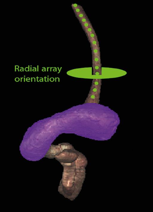
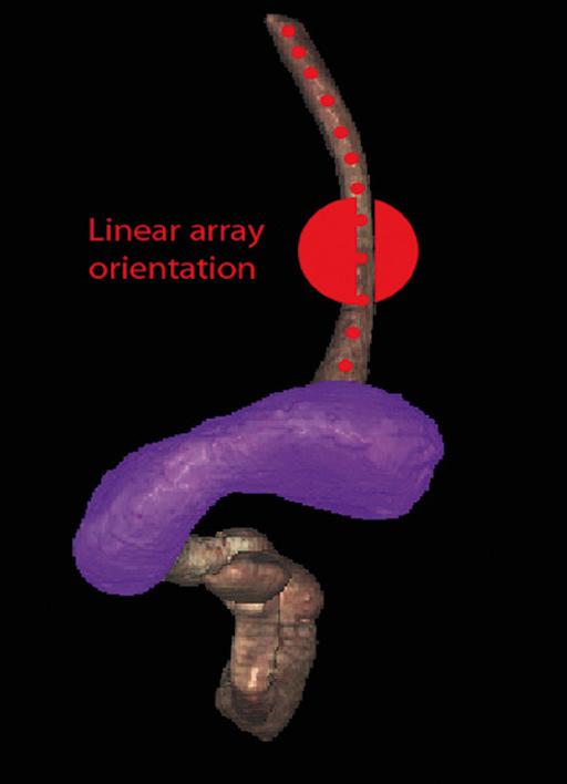
This chapter uses the terms “radial array orientation” to describe planar anatomy which would be found perpendicular to a line going through the digestive tract (as would be generated by a radial array echoendoscope, Figure 1.1) and “linear array orientation” for planar anatomy generated parallel to a line going through the digestive tract (as would be generated by a linear array echoendoscope, Figure 1.2).
Normal EUS anatomy from the esophagus
Radial array orientation (Video 1.1)
Video 1.1 starts with Visible Human Models of the left atrium (purple), trachea and bronchi (light blue), aorta and pulmonary arteries (red), vena cava (dark blue), and the esophagus (brown). A plane is shown passing through the esophagus. This plane contains the transaxial cross‐sectional anatomy images which then follow, starting in the oropharynx and going caudally. The upper esophageal sphincter (UES) is identified. As the images proceed distally, the trachea and esophagus can be followed to a point where the brachiocephalic left carotid and left subclavian arteries are evident just above the aortic arch. Below the aortic arch is the aortopulmonary window. The azygos arch can be seen exiting the superior vena cava (SVC). This occurs just above the tracheal bifurcation. The esophagus (labeled as “E”) is surrounded by the descending aorta, the vertebrae, and the trachea. The thoracic duct (not labeled) is visible between the aorta and vertebrae, inferior to the esophagus. Going distally, the pulmonary artery becomes prominent. The region between the right mainstem bronchus (RMB) and left mainstem bronchus (LMB) is the subcarinal space. The video progresses to a level where the left atrium surrounds the superior aspect of the esophagus and then the video ends as the esophagus passes the gastroesophageal junction.
An image plane cross‐section taken from a radial array orientation at the level of the subcarinal space is shown in Figure 1.3.
Linear array orientation (Video 1.2)
Video 1.2 starts with the same models as above (the left atrium [purple], trachea and bronchi [light blue], aorta and
Artifon.
pulmonary arteries [red], vena cava [dark blue], and the esophagus [brown]). The plane shows potential ways that cross‐sectional anatomy can be generated. The video then shows a sagittal image with the descending aorta inferior to the esophagus, much as what is done during linear array EUS. In this orientation the pulmonary artery (PA) and left atrium are superior. The image plane is rotated to bring the left atrium and pulmonary artery to the inferior side of the esophagus. The models are then shown again, and the plane is moved in the caudal and cephalad directions, much as during EUS.
Normal EUS anatomy from the stomach
Radial array orientation (Video 1.3)
Endoscopic ultrasound of the stomach differs from EUS at other sites since the stomach does not constrain the endoscope tightly. It is important to follow anatomical structures (such as in a station approach) to avoid getting lost.
The video shows models of the stomach, esophagus, duodenum, gallbladder, pancreas (brown), the aorta, splenic
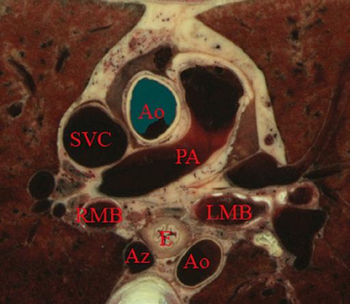
Figure 1.3 Transaxial cross‐section of digital anatomy taken at the level of the subcarinal space. Ao, aorta (both ascending, superior in the image, and descending, inferior in the image, are shown); Az, azygos vein; PA, pulmonary artery; RMB and LMB, right and left mainstem bronchi; SVC, superior vena cava.
Figure 1.1 Visible Human Model of esophagus, stomach, and duodenum. The green circle shows a plane perpendicular to the axis and is similar to a plane developed during radial array endosonography.
Figure 1.2 Visible Human Model of esophagus, stomach, and duodenum. The red circle shows a plane parallel to the axis and is similar to a plane developed during linear array endosonography.
artery, hepatic artery and left gastric artery (red), adrenal glands (pink), and splenic, superior mesenteric veins (dark blue) as viewed from behind. A plane is passed that is similar to the image plane generated during radial array EUS. The resultant cross‐sectional anatomy starts at the level of the gastroesophageal junction, with the aorta and inferior vena cava (IVC) labeled. The aorta (which is collapsed) is followed, which brings the pancreas and left adrenal gland into view. The first artery that comes off the aorta in the abdomen is the celiac artery. There is a trifurcation into the splenic, hepatic, and left gastric arteries (LGA), although the LGA is generally smaller and difficult to see. It is shown in the video at the “x” just before the bifurcation into the celiac and hepatic arteries as identified.
The superior mesenteric artery (SMA) comes off the aorta just distal to the celiac artery. Various endoscope maneuvers can be used to bring the portal confluence into view, and then the splenic vein can be used as a guide to visualize the pancreas body, left adrenal, kidney, and spleen. The diaphragm can be easily imaged between the kidney and the vertebrae.
Linear array orientation (Video 1.4)
The linear array exam also follows the aorta to the stomach, but, as shown Video 1.4, the image plane across the pancreas is generally obtained through a sweeping motion. The first major gastric landmark is the origin of the celiac artery and SMA from the aorta (Figure 1.4). The superior mesenteric vein (SMV), portal vein, and splenic vein can be used as guides to go back and forth across the pancreas and in the
process, the left adrenal, kidney, and spleen can be seen. The splenic artery runs roughly parallel to the splenic vein, but is generally tortuous.
Normal EUS anatomy from the duodenum
Radial array orientation (Video 1.5)
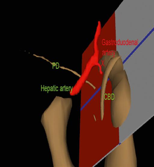
The radial array EUS examination through the duodenum follows a constrained path, but the endoscope can be rotated to put various structures into the inferior aspect of the image plane, as shown in the models of the duodenum, pancreas (brown), portal and superior mesenteric veins (blue), aorta (red), and SMA (silver). There are many structures of interest in a rather small area, and most of the images obtained are from the posterior view, with the liver to the right and the pancreas to the left of the image screen. After leaving the pylorus, the pancreas can be oriented with the tail pointed either to the left or inferiorly, and the splenic vein runs in the same direction as the pancreas. Going through the duodenal bulb, the gastroduodenal artery (GDA) often appears. Without Doppler, the GDA can be confused with the common bile duct (CBD) since these structures are nearly parallel in orientation and are very close to each other. As the apex of the duodenal bulb is reached, the image plane captures a longitudinal view of the CBD and the portal vein. As the descending duodenum is reached, the bile duct is seen in cross‐section and the IVC comes into view. As the third part of the duodenum is reached, the image plane rotates in such a way as to give a longitudinal cut through the IVC and then passes underneath the junction of the SMA with the aorta. Branches of the SMV can be found and the renal vein is visible in the “armpit” formed at the insertion of the SMA into the aorta. A special area is then highlighted in Video 1.5. Models show how the gastroduodenal artery and the hepatic artery (in red) relate to the CBD (in orange).
Figure 1.5 shows a model with an image plane and Figure 1.6 shows the resultant planar anatomy, which forms the stack sign – a phenomenon in which the portal vein, CBD, and main pancreatic duct are captured in the same field.
Linear array orientation (Video 1.6)
The linear array exam of the duodenum is an excellent way to see the CBD and pancreatic head. The anatomy is difficult to understand since the endoscope image is tipped into the C‐sweep of the duodenum, and then the image plane is swept in various angles, resulting in a cross‐sectioning of the CBD and pancreatic duct (PD). The image planes employed can be appreciated from observing the models in the video. The cross‐sections obtained can be positioned to first give a longitudinal view of the CBD and both longitudinal views and cross‐sections of the portal vein and SMV.
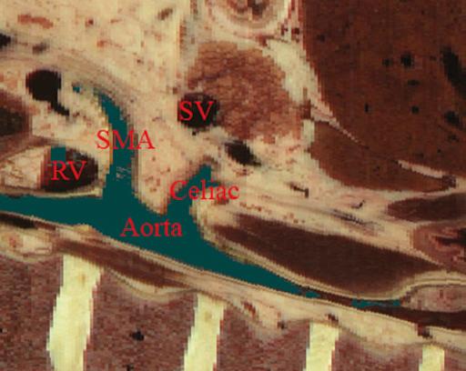
Figure 1.4 Sagittal cross‐section of digital anatomy at the level of the gastroesophageal junction, similar to a view seen during linear array endoscopic ultrasound (EUS). The celiac and superior mesenteric arteries (SMA) are shown at their insertion into the aorta. The renal vein (RV) is shown adjacent to the SMA and the splenic vein is shown adjacent to the pancreas.
Image plane that generates “stack sign”
Image plane that generates “stack sign”
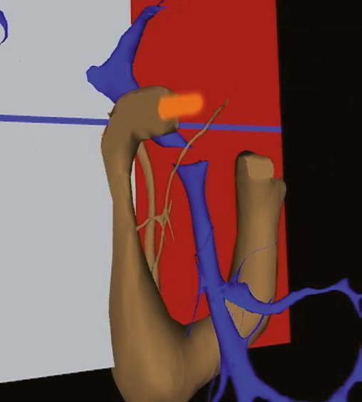
Figure 1.5 Visible Human Model of an image plane that is in the location in which radial array endoscopic ultrasound (EUS) generates the “stack sign”, in which the portal vein, common bile duct (CBD), and pancreatic duct are in the same field. A probe in orange is shown going into the proximal duodenum. The superior mesenteric vein (SMV) is also shown.
Figure 1.6 The cross‐sectional anatomy within the plane shown in Figure 1.3. The common bile duct (CBD), pancreatic duct (PD), and portal vein are all in the same field (“stack sign”).
Figure 1.7 Visible Human Model with a plane that is in a location similar to what can be generated during linear array endoscopic ultrasound (EUS), showing the relative position of the gastroduodenal artery, pancreatic duct (PD), hepatic artery, and common bile duct (CBD).
As seen in the first part of Video 1.6, if the endoscope is in the second part of the duodenum, the bile duct goes to the ampulla away from the transducer and the liver is towards the transducer. If the endoscope is in the duodenal bulb, as shown in the second part of the video, the liver is away from the transducer.
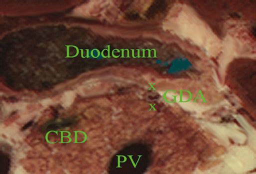
The GDA drapes over the portal vein and can be found most readily using Doppler. Figure 1.7 shows a model and Figure 1.8 the resultant cross‐section where the GDA can be found.
Normal EUS anatomy from the rectum
Radial array orientation, male (Video 1.7)
Video 1.7 shows models of various male pelvic structures, starting with the rectum and sigmoid colon, the aorta, and the iliac arteries with internal and external branches. The SMA is included to show the anterior direction of the models. The prostate, bladder, coccyx, and sacrum are added sequentially. A second set of models is then shown which contains the rectum, sigmoid colon, prostate, bladder, coccyx, sacrum, external iliac arteries (red), veins (blue), as well as three‐dimensional models of the internal and external anal sphincters. The sphincters and sigmoid colon are then removed.
Planar anatomy in the radial array orientation from the male rectum is then shown, starting distally and moving proximally. The anal sphincters are labeled, followed by the
Figure 1.8 Cross‐sectional anatomy generated within the plane shown in Figure 1.5. The gastroduodenal artery (GDA) and common bile duct (CBD) are shown with the pancreatic head. The portal vein (PV) is shown near the portal confluence.
prostate, urethra, levator ani, and coccyx. The sacrum and seminal vesicles are then shown, followed by the right internal iliac artery.
Radial array orientation, female (Video 1.8)
Video 1.8 starts distally at the end of the anal canal. The internal and external sphincters are shown, and residual stool is present in the rectum. Moving proximally, the vagina and urethra are shown, followed by the cervix and bladder.
Linear array orientation, male (Video 1.9)
Video 1.9 starts with a sagittal plane through the pelvis with the body facing the left. The prostate, rectum, anal canal, and bladder are identified. The plane is rotated, and the seminal vesicles and internal anal sphincter are labeled. The coccyx and sacrum are apparent at the start and end of the video but are unlabeled.
Linear array orientation, female (Video 1.10)
Video 1.10 starts with a sagittal plane through the pelvis with the body facing the left and slightly face down. The anal canal, rectum, uterus, and bladder are identified. Stool is present in the rectal vault. The plane is rotated, and towards the end of the video the internal anal sphincter (IS) and external anal sphincter (ES) are identified.
Vascular videos
Arterial (Video 1.11)
Video 1.11 shows models of some of the main arteries that are visualized during endosonography. A close‐up view shows the celiac artery with its branches (hepatic, splenic, and left gastric arteries). The gastroduodenal and pancreaticoduodenal arteries are shown coming off the hepatic artery. The internal and
external iliac arteries are then identified, followed by identification of the arteries associated with the aortic arch (left subclavian, left carotid, brachiocephalic) and the branches of the brachiocephalic (right subclavian and right carotid). Various organs are then placed in the model starting with the esophagus, then pancreas, stomach, and duodenum.
Venous (Video 1.12)
Some of the major veins visualized during endosonography are shown. At first, the vena cava and right atrium are identified, after which, the renal veins and azygos veins are added. The portal system with the portal vein, SMV, splenic vein, and inferior mesenteric vein (not labeled) are placed in blue. The systemic veins are then colored and removed. The pancreas is placed on the portal vein and its branches, showing how the head runs parallel to the SMV and the tail runs parallel to the splenic vein.
Endobronchial ultrasound anatomy (Video 1.13)
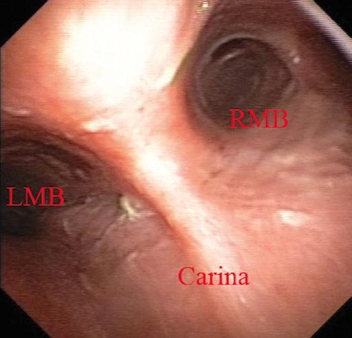
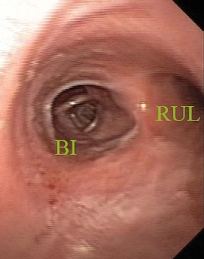
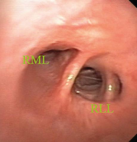
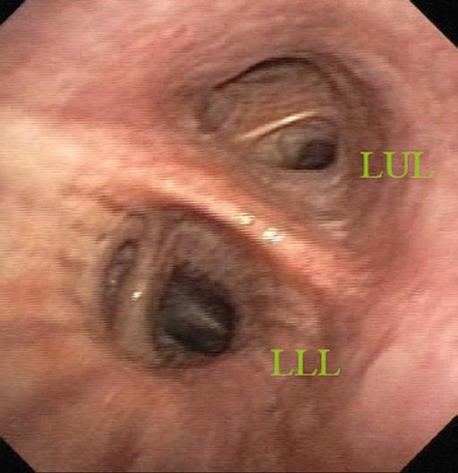
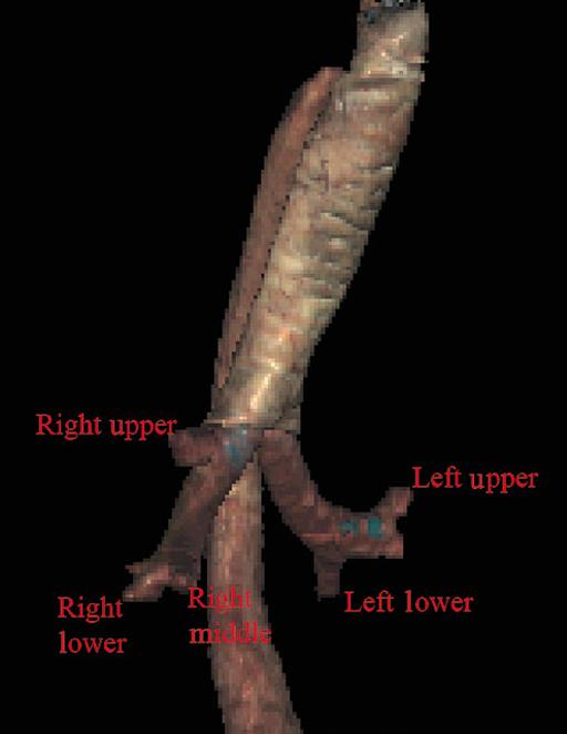
Extratracheal anatomy is similar to extraesophageal anatomy and many of the structures seen in the extratracheal spaces are the same as what is seen in the extraesophageal spaces. The endoluminal views of the trachea are oriented so that the membranous trachea is inferior and is splayed wider than the cartilaginous trachea at the level of the carina, putting the right mainstem bronchus (RMB) to the right and the left mainstem bronchus (LMB) to the left (Figure 1.9). As one goes right the bronchus immediately branches superiorly towards the right upper lobe (RUL), and continues straight as bronchus intermedius (BI) (Figure 1.10), which then branches towards the right middle lobe (RML) and right lower lobe (RLL) of the lung (Figure 1.11). Going left from the carina, one goes down the relatively long left mainstem bronchus until it branches towards the left upper lobe (LUL) and left lower lobe (LLL) of the lung (Figure 1.12). An overview of the bronchial tree is shown in Figure 1.13. Video 1.13 starts with the cervical trachea. All images are in a linear array orientation as endobronchial ultrasound (EBUS) is exclusively linear. The esophagus is inferior and the brachiocephalic artery and vein are superior. The video begins with rotation of the image plane. The superior part of the plane moves left and the inferior part moves right. This moves the esophagus out of view and brings the left subclavian artery and left carotid artery into the inferior part of the image. Eventually, the esophagus is seen in the superior part of the image and, with continued motion, the esophagus again appears inferior to the trachea. At this point, the image plane moves caudally to the carina. The right pulmonary artery, brachiocephalic artery (BA), and left brachiocephalic vein (LBV) are labeled. The plane is again rotated to splay the right (RMB) and left (LMB) mainstem bronchi apart. The plane is then moved to better visualize the right mainstem bronchus, showing the branch to the right upper lobe (RUL), the azygos arch (AzArch), the bronchus intermedius (BI).
This same plane shows the relation of the aortic arch (AoArch) and left pulmonary artery to the left mainstem bronchus (LMB). As the plane goes down the right mainstem bronchus/bronchus intermedius (RMB) towards its next bifurcation, the azygos arch (AzAr), right pulmonary artery (RPA), and right pulmonary vein (RPV) are shown.
The plane is brought back to the carina to visualize the left mainstem bronchus (LMB), and the azygos arch (AzAr), aortic arch (AoAr), left pulmonary artery (LPA), and vein (LPV) are identified. The branching to the left upper lobe (LUL) and left lower lobe (LLL) are shown, and the
and left pulmonary artery are labeled.
Figure 1.12 Endobronchial view of bifurcation of the left mainstem bronchus towards the left upper lobe (LUL) and left lower lobe (LLL).
aorta (Ao)
Figure 1.10 Endobronchial view of the first branch of the right mainstem bronchus towards the right upper lobe (RUL) and the bronchus intermedius (BI).
Figure 1.11 Endobronchial view of the bifurcation of the bronchus intermedius towards the right middle lobe (RML) and the right lower lobe (RLL).
Figure 1.9 Endobronchial view of the carina, showing the right (RMB) and left (LMB) mainstem bronchi.
Chapter video clips
Video 1.1 Esophageal‐related models and cross‐sectional anatomy: radial orientation.
Video 1.2 Esophageal‐related models and cross‐sectional anatomy: linear orientation.
Video 1.3 Gastric‐related models and cross‐sectional anatomy: radial orientation.
Video 1.4 Gastric‐related models and cross‐sectional anatomy: linear orientation.
Video 1.5 Duodenal‐related models and cross‐sectional anatomy: radial orientation.
Video 1.6 Duodenal‐related models and cross‐sectional anatomy: linear orientation.
Video 1.7 Male rectum‐related models and cross‐sectional anatomy: radial orientation.
Video 1.8 Male rectum‐related cross‐sectional anatomy: linear orientation.
Video 1.9 Female rectum‐related cross‐sectional anatomy: radial orientation.
Video 1.10 Female rectum‐related cross‐sectional anatomy: linear orientation.
Video 1.11 Arterial models.
Video 1.12 Venous models.
Video 1.13 Bronchial anatomy in a linear orientation.
Figure 1.13 A Visible Human Model of the bronchial tree.
Esophagus: Radial and Linear
James L. Wise and John C. Deutsch
Essentia
Health Care Systems, Duluth, MN, USA
Layers of the esophageal wall
Staging the depth of involvement of tumors and the layer of origin of subepithelial masses is an important component of competency in endoscopic ultrasonography (EUS). An intimate knowledge of the normal layers of the esophageal wall is critical for this to be done accurately. The wall of the esophagus has four readily appreciable layers by EUS using standard operating frequencies (5–12 MHz). The layers are seen in concentric, alternating rings of hyperechoic and hypoechoic structures emanating out distally from the tip of the endoscope. Starting with the layers closest to the scope tip, they are as follows:
• Interface echo between the superficial mucosa and water (hyperechoic).
• Deep mucosa (hypoechoic).
• Submucosa plus the acoustic interface between the submucosa and muscularis propria (hyperechoic).
• Muscularis propria minus the acoustic interface between the submucosa and muscularis propria (hypoechoic).
If a higher resolution frequency probe is used, greater number of layers could be visualized as detailed in Chapter 4. The esophagus lacks an obvious fifth layer as there is no serosa.
In our opinion, visualization and discernment of the layers of the esophageal wall is usually best accomplished using radial compared to linear instruments.
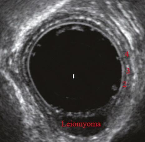
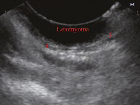
Figure 2.1 shows the esophageal walls using radial and linear instruments. To help separate the layers, these images include a muscularis mucosae leiomyoma that was subsequently resected. Images show subepithelial hypoechoic lesion in echolayer II as well as in the other defined layers of the esophageal wall.
Normal radial extraesophageal anatomy (Video 2.1)
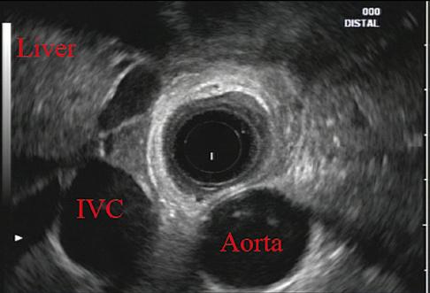
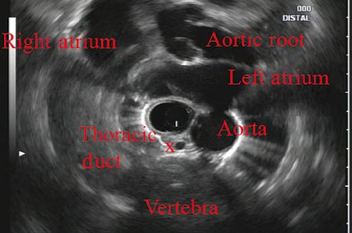
Standard examination of the esophagus and mediastinum begins with advancing the radial instrument to the gastroesophageal (GE) junction at or near the squamocolumnar junction. At this level the aorta is seen as an anechoic circular structure in the 5 o’clock position. The descending aorta is kept in this position as all radial mediastinal imaging will then correlate quite nicely with cross‐sectional imaging. Other structures visible at the level of the GE junction are the inferior vena cava (IVC) seen between 7 and 9 o’clock and the liver between 6 o’clock and 12 o’clock surrounding the IVC (Figure 2.2).
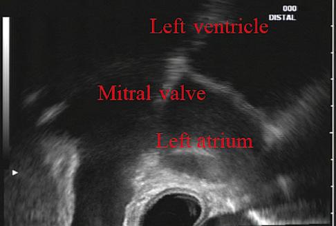
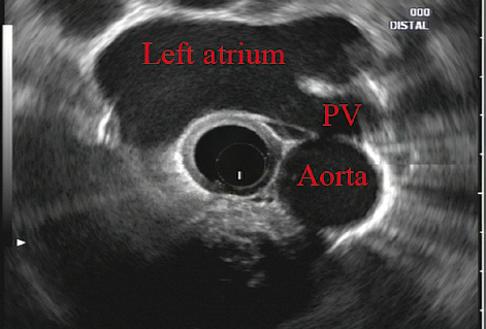
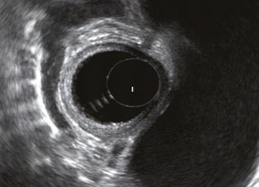
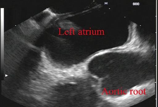
As the scope is withdrawn, the vena cava moves clockwise and superiorly into the right atrium. The spine soon comes into view adjacent to the descending aorta at 6 o’clock. Further withdrawal upward to usually around 30–35 cm reveals the anechoic chamber of the left atrium in the 12 o’clock position (Figure 2.3). With this field, relatively slight movement of the scope will reveal the mitral valve (Figure 2.4), aortic root, and the aortic valve (Figure 2.5). In the inferior portion of the field the descending aorta, the spine, the thoracic duct, and a relatively prominent azygos vein can be seen.
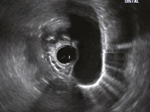
As the scope is withdrawn the bronchi come together at the carina. At or just proximal to this level the azygos arch (Figure 2.6) can be identified traveling superiorly and laterally into the superior vena cava. This is also the area of the aortopulmonary (AP) window at approximately 2 o’clock.
The endoscope can be pushed down from here or pulled up slightly from the position of the left atrium to reach the subcarinal space. Of interest in the subcarinal space are the right and left mainstem bronchi seen emanating out as ribbed‐like
Atlas of Endoscopic Ultrasonography, Second Edition. Edited by Frank
Figure 2.3 Radial array image at the level of the left atrium. PV, pulmonary vein.
Figure 2.4 Radial array image at the level of the mitral valve.
Figure 2.5 Radial array image at the level of the aortic root.
(a) (b)
Figure 2.1 (a) Radial array image of esophageal wall with small echolayer II leiomyoma. (b) Linear array image of esophageal wall with small echolayer II leiomyoma.
air‐filled structures. As many have suggested, these can be imagined to have the appearance of two headlights.
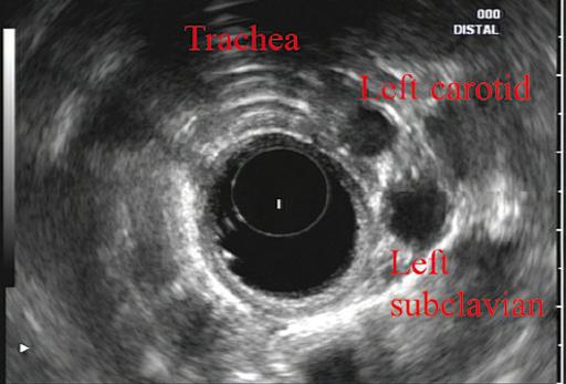
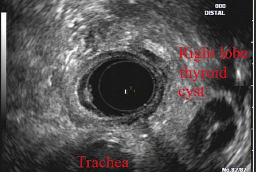
More proximally from the area at the AP window the aorta elongates and forms the aortic arch (Figure 2.7). This usually creates a semicircle on the entire right side of the image correlating to the left‐sided arch. However, with usual orientation the aorta should not cross the midline. The left carotid and left subclavian artery can easily be seen to leave the aortic arch as small round structures on the right side of the image (Figure 2.8). The brachiocephalic artery can sometimes be seen as well superior to the carotid on the right. As the scope is withdrawn the thyroid comes into view. For example, on the right of Figure 2.9 a prominent thyroid can be seen with a cystic structure within it.
Normal linear thoracic anatomy
The linear scope is advanced to the GE junction by following the descending aorta from the level of the arch downward
(Figure 2.10). In order to follow this path, the scope is usually torqued clockwise 90–180 degrees and, as the aorta is followed down, the scope is gently rotated counterclockwise to stay on the aorta. As seen in Video 2.2, the thyroid is visualized briefly and the scope is then advanced to the level of the GE junction.
The origin of the celiac artery (Figure 2.11) is identified and then the scope can be withdrawn. This is the standard reference point for the beginning of the exam during withdrawal. Examination of the extraesophageal and thoracic structures is more time consuming than the radial approach as this echoendoscope’s narrow focal point has to be torqued back a further 180 degrees to cover the same field of examination. This is done by withdrawing the scope at increments with constant back and forth torque.
As the scope is withdrawn 3–5 cm back from the GE junction, the scope will need to be rotated 180 degrees off the aorta to see the left atrium and cardiac structures. The cardiac structure can be discerned quite readily using the linear scope. The mitral valve is just adjacent to the aortic root,
Figure 2.8 Radial array image at the level of the left carotid and subclavian arteries.
Tracheal bifurcation
Azygos arch
Thoracic duct X Aortic arch
Figure 2.6 Radial array image at the level of the azygos arch.
Figure 2.9 Radial array image at the level of the thyroid.
Azygos vein
Tracheal bifurcation x Aortic arch
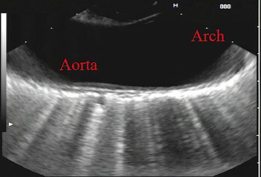
Figure 2.7 Radial array image at the mid aortic arch.
which is just at clockwise rotation from the mitral valve. The aortic valve can be visualized at various angles with appropriate endoscopic manipulation given its position relative to the esophagus (Figure 2.12).
Withdrawing from the level of the left atrium by 1–2 cm reveals the subcarinal space. This is the area between the pulmonary artery and the left atrium. The bifurcation of the trachea by definition occurs at this level as well.
The AP window is just proximal to this area by several centimeters’ orientation and is slightly clockwise torque from the subcarinal space. The space between the aortic arch and the pulmonary artery make up this region. This is below the level of the aortic arch by a few centimeters. There is a small node seen on the image which could be
readily sampled via endoscopic ultrasound‐guided fine needle aspiration (EUS‐FNA) (Figure 2.13).
The azygos arch is also visualized around this area, just at or slightly below the aortic arch. The azygos vein can be followed distally along the spine, as in the accompanying Video 2.2. Occasionally intercostal veins are visible.
Chapter video clips
Video 2.1 Radial array examination of the extraesophageal spaces.
Video 2.2 Linear array examination of the extraesophageal spaces.
Figure 2.10 Linear array image at the mid aorta.
Aorta
GE junction
Celiac
Figure 2.11 Linear array image at the level of the celiac artery.
Figure 2.13 Linear array image at the aortopulmonary window (APW). PA, pulmonary artery.
Figure 2.12 Linear array image at the aortic root.
Normal Mediastinal Anatomy by EUS and EBUS
Juan Corral1, Sebastian Fernandez‐Bussy2, and Michael B. Wallace1
1 Division of Gastroenterology and Hepatology, Mayo Clinic College of Medicine, Jacksonville, FL, USA
2 Division of Pulmonary Medicine and Critical Care, Mayo Clinic College of Medicine, Jacksonville, FL, USA
Introduction
The mediastinum is a common anatomical location for lymph node (LN) metastases in lung cancer as well as many other malignant and inflammatory conditions. The presence and specific location of mediastinal LN metastases in non‐small cell lung cancer (NSCLC) dictates therapy with surgery for localized disease, combination therapy when contralateral LNs are involved, and palliative therapy when contralateral LNs and metastases are encountered. Unfortunately, cross‐sectional imaging with computed tomography (CT), magnetic resonance imaging (MRI), or positron emission tomography (PET) alone is not adequate to confirm a diagnosis; thus, a tissue sample is preferred. Recently, it has been suggested that the use of endoscopic ultrasound‐guided fine needle aspiration (EUS‐FNA) associated with endobronchial ultrasound‐guided transbronchial fine needle aspiration (EBUS‐TBNA) can adequately sample LNs in the mediastinum, avoiding the need for a futile surgery.
The purpose of this chapter is to provide the basic anatomical information as well as technical maneuvers used to investigate the mediastinum successfully.
Anatomical definitions
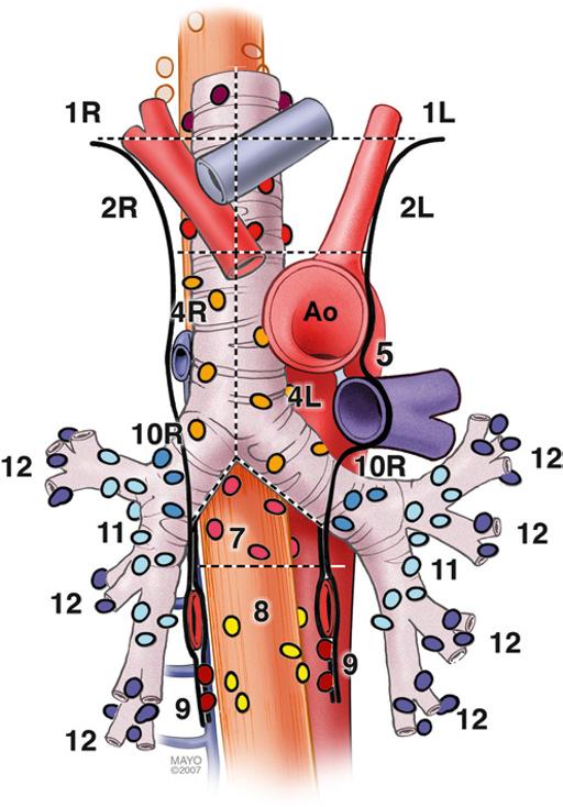
The LNs in the mediastinum were classified in different stations based on surgical and anatomical landmarks for the purpose of staging lung cancer but this schema is now widely used in other chest diseases (Figure 3.1). The LNs with their respective stations and corresponding anatomical locations are described in Table 3.1.
EUS‐FNA is usually best suited to sample LNs adjacent to the esophagus which runs posterior to the trachea. Because
Atlas of Endoscopic Ultrasonography, Second Edition. Edited by Frank
of ultrasound artifacts created by the air‐filled trachea, lesions immediately anterior to the trachea are not well seen. EUS‐accessible stations include 2L, 2R, 4L, 4R, 5, 7, 8, 9, and, sometimes depending on the size, station 6. On the other hand, EBUS‐TBNA can target LNs either anterior or lateral to the trachea to the level of the carina, and alongside the left and right bronchial tree including stations 2L, 2R, 4L, 4R, 7, 10, and 11. Although both procedures overlap in stations 2 L/R, 4 L/R, and 7, in other stations they are complementary, and in combination allow nearly complete mediastinal access.
Equipment
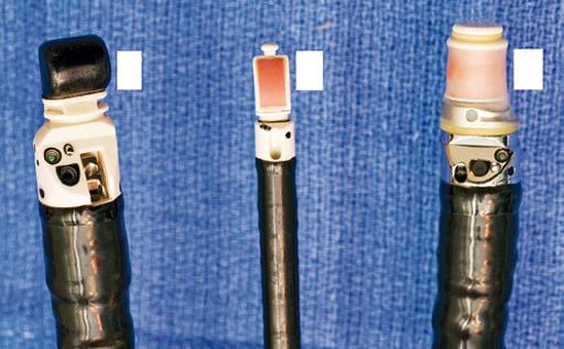
Radial and curvilinear array echoendoscopes are available (Figure 3.2), with scanning radius ranging from 270–360 degrees for radial to 100–180 degrees for the linear echoendoscope. These scopes have standard accessory channels (2.0–2.8 mm) and larger accessory channels (3.7 mm) capable of delivering needles and other therapeutic devices such as a 10 French (Fr) plastic stent.
EUS can use several types of needles: 19 gauge (G), 22 G, and 25 G for FNA, as well as Tru‐cut needles for core biopsy. The needle is occluded with a stylet during passage through the gastrointestinal tract wall and bronchial wall to minimize contamination from passage through those structures. EBUS equipment comprises a curvilinear array echoendoscope with an outer diameter of 6.7 mm and a biopsy channel of 2 mm. The ultrasonic frequency is 7.5 MHz with a penetration depth of 4–5 cm, making it well suited for FNA of LNs and lung masses through the trachea and bronchi. A 22 G needle is used to perform TBNA in the same manner as in EUS. Both systems have integrated oblique‐viewing optics to guide intubation and limited inspection.
Thomas
and Everson
Gress,
Savides, Brenna Casey,
L. A. Artifon.
Endoscopic ultrasound technique
The initial examination can be performed with either the radial or linear array echoendoscope; however, the linear scope is required to perform FNA. Given the obvious efficiencies, we prefer to use a single linear echoendoscope for both imaging and FNA.
Linear scanning
The balloon should be deflated or inflated only slightly to provide good acoustic coupling with the tissue. The mediastinum is imaged by first finding the descending aorta starting at the cardia. The examination can be performed by rotating 360 degrees from the cardia, then withdrawing the shaft 4–5 cm and performing another rotation. Alternatively, one can survey from the cardia to the cervix, then rotating 90 degrees and repeating the maneuver until the whole mediastinum is examined. It is useful to use the following five stations as described by Deprez (Videos 3.1.1–3.1.3). For radial examination, see Video 3.2.
Table 3.1 Mediastinal lymph node stations with their anatomical correlations. Level
Superior mediastinal lymph nodes
and retrotracheal
paratracheal (including azygos nodes)
Aortic lymph nodes
Aortopulmonary (AP) window or subaortic
Para‐aortic (ascending aorta and phrenic)
Inferior mediastinal lymph nodes
(below carina)
ligament
Inferior posterior mediastinum
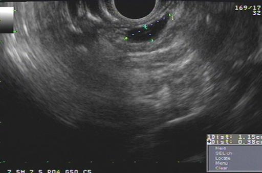
The descending aorta is a large echo‐poor longitudinal structure on linear array with a bright deep wall due to the air interface with the left lung. Clockwise rotation will sequentially image left lung, left pleura, left atrium, right lung, right pleura, azygos vein, and spine. The azygos vein can be localized by rotating approximately 30 degrees counterclockwise from the descending aorta. It is a thin echo‐poor structure that can be followed proximally to its union with the superior vena cava. This is the area of LN stations 8 and 9 (Figure 3.3).
Figure 3.1 Mediastinal lymph node stations.
(a) (b) (c)
Figure 3.2 Types of echoendoscopes: (a) linear probe; (b) endobronchial probe; (c) radial probe.
Subcarinal area
At approximately 30 cm the subcarinal area is easily recognized by finding the left atrium, a large hypoechoic structure with cardiac motion, and pulling back until it disappears on the left edge of the screen. Then one should have the pulmonary artery in the right portion of the screen (Figure 3.4). Slight movements to the right and left have to be performed to completely interrogate this station. This is the area of LN station 7 (Videos 3.3 and 3.4).
Aortic arch area
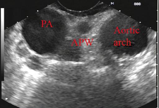
The azygos arch is located at 24–25 cm from the incisors. The aortopulmonary (AP) window (station 5) is situated between
the aortic arch and the pulmonary artery. The AP window is found by following the aorta cephalad until its arch, rotating clockwise approximately 90 degrees, then advancing 1–2 cm with slight tip up of the echoendoscope. The aorta will be the echo‐poor structure on the right and the pulmonary artery will be to the left; the AP window is the space between the two just outside the AP ligament (which is not seen by EUS). The 4L region is immediately medial (close to the esophagus and EUS scope) to the AP window (Figure 3.5). Alternatively, from the subcarinal area, rotating 90 degrees counterclockwise, crossing the left main bronchus and pulling it back 2–3 cm will put you in the same location. Further withdrawal of the echoendoscope with slight rotation will show the origin of the left subclavian artery. Occasionally, the left carotid artery can be seen above the brachiocephalic (innominate) vein.
Cervical area
Between 22 and 24 cm from the incisors, the superior part of the lungs can be imaged along with the trachea, cricoid bone, jugular veins, and carotid arteries.
Thyroid gland
At 17–20 cm from the incisors, the inferior thyroid gland can be imaged as well as cervical LNs, which can be targeted for FNA.
Radial scanning
For radial scanning, one should enter the stomach, inflate the balloon, and pull back the scope until the GE junction. The aorta with be visualized as a large round echo‐poor structure. The aorta should be rotated to the 5 o’clock position, and the spine will be at 7 o’clock with the azygos vein in the middle. Then the balloon should be deflated and a slow pull‐back is
Figure 3.3 Lymph node at station 8 (between calipers).
L node AO PA
Figure 3.5 Aortopulmonary window station (stations 4L, 5 and 6). AO, aorta; L node; lymph node; PA, pulmonary artery.