Energy Storage for Modern Power System Operations
Edited by Sandeep Dhundhara and
Verma
Yajvender Pal
This edition first published 2021 by John Wiley & Sons, Inc., 111 River Street, Hoboken, NJ 07030, USA and Scrivener Publishing LLC, 100 Cummings Center, Suite 541J, Beverly, MA 01915, USA © 2021 Scrivener Publishing LLC
For more information about Scrivener publications please visit www.scrivenerpublishing.com.
All rights reserved. No part of this publication may be reproduced, stored in a retrieval system, or transmitted, in any form or by any means, electronic, mechanical, photocopying, recording, or otherwise, except as permitted by law. Advice on how to obtain permission to reuse material from this title is available at http://www.wiley.com/go/permissions.
Wiley Global Headquarters
111 River Street, Hoboken, NJ 07030, USA
For details of our global editorial offices, customer services, and more information about Wiley products visit us at www.wiley.com.
Limit of Liability/Disclaimer of Warranty
While the publisher and authors have used their best efforts in preparing this work, they make no representations or warranties with respect to the accuracy or completeness of the contents of this work and specifically disclaim all warranties, including without limitation any implied warranties of merchantability or fitness for a particular purpose. No warranty may be created or extended by sales representatives, written sales materials, or promotional statements for this work. The fact that an organization, website, or product is referred to in this work as a citation and/or potential source of further information does not mean that the publisher and authors endorse the information or services the organization, website, or product may provide or recommendations it may make. This work is sold with the understanding that the publisher is not engaged in rendering professional services. The advice and strategies contained herein may not be suitable for your situation. You should consult with a specialist where appropriate. Neither the publisher nor authors shall be liable for any loss of profit or any other commercial damages, including but not limited to special, incidental, consequential, or other damages. Further, readers should be aware that websites listed in this work may have changed or disappeared between when this work was written and when it is read.
Library of Congress Cataloging-in-Publication Data
ISBN 9781119760337
Cover image: Wikimedia Commons
Cover design by Russell Richardson
Set in size of 11pt and Minion Pro by Manila Typesetting Company, Makati, Philippines
Printed in the USA
10 9 8 7 6 5 4 3 2 1
5.2
4.4.1
5.3
5.1.3
5.4
7.2
7.3
8.1
7.3.2
8.1.1
8.1.2
8.1.3.4
8.7.2
Preface
The power sector worldwide has undergone a huge transformation and the focus is to make it sustainable, environmental friendly, reliable, and highly efficient. As a result, a significant share of highly intermittent but clean renewable sources are being integrated into the power system using advanced technological components. The stochasticity of these renewable sources poses a big challenge to the efficient operation of the power system and storage will play a big role in its smooth and reliable operation. Technological developments have made it possible to use batteries and other storage systems for managing the operation of the power system. That’s why we chose to come out with an edited book having some applications of the storage system in power system operation.
Our main aim is to illustrate the potential of energy storage systems in different applications of the modern power system considering recent advances and research trends in storage technologies. The book contains some useful case studies of the application of storage systems besides an introductory topic on modern storage system technologies. The book covers storage applications in demand response programs, supporting virtual inertia requirements of the power system, electric vehicle, distribution system planning and operation, microgrid operation, frequency control of the interconnected power system, and fuel cell as an alternative to the renewables. The applications of the storage have been demonstrated through simulation case studies of some standard practical systems. These areas are going to play a very important role in future smart grid operations. The research scholars, faculty members, and power industry people will find this book very useful and interesting.
In order to cover such different topics, we approached to various potential researchers and authors for the contribution of the chapters. We received more than 30 chapters but could accommodate only 10 chapters in this edition. We are thankful to all the authors who have contributed their chapters to this book. We were also fortunate enough to have a group of excellent reviewers who helped us in the review process.
Preface
We are also thankful to our mentor Prof. Ashwani Kumar Sharma from NIT Kurukshetra, Haryana, India for the guidance, support, and constant motivation during the editing of this book. As constant researches are going on in the field of storage technologies and power system, we will come up with a second part of the book covering some more areas of storage application in power system operation and control.
Sandeep Dhundhara Yajvender Pal Verma
Introduction to Energy Storage Systems
Rajender Kumar Beniwal1*, Sandeep Dhundhara2 and Amarjit Kalra2
1Department of Electrical Engineering, Guru Jambheshwar University of Science & Technology, Hisar, Haryana, India
2Department of Basic Engg, College of Agricultural Engg. and Tech., CCS Haryana Agricultural University, Hisar, India
Abstract
This chapter presents an introduction to the Energy Storage Systems (ESS) used in the present power system. Nowadays, renewable energy sources–based generating units are being integrated with the grid as they are green and clean sources of energy and also address environmental concerns. Therefore, electrical energy storage systems become one of the main components which deal with the grid instability that occurs due to the intermittent nature of these renewable energy sources. In this chapter, different types of energy storage systems reported in the literature have been presented. An effort has been made to discuss all the details such as the principle of operation, different components, and characteristics of each type of energy storage technology. Different characteristics of energy storage techniques are compared in tabular form with their pros and cons. The main objective of this chapter is to introduce the concept of storage techniques used in power systems and their needs and applications. Classification of storage systems has been presented based on short-term, medium, and long-term usage capacity.
Keywords: Energy storage system, distributed energy resources, microgrid, power system, renewable energy, storage techniques
*Corresponding author: mail.rajendera@gmail.com
Sandeep Dhundhara and Yajvender Pal Verma (eds.) Energy Storage for Modern Power System Operations, (1–32) © 2021 Scrivener Publishing LLC
1.1 Introduction
Electrical energy is now becoming the backbone of every country as it directly helps to enhance economic growth through its several applications in the national grid. The development of any industrial infrastructure is directly associated with the availability of electrical energy and due to this growing industrial infrastructure, the electricity demand is also increasing. As per the hike in demand for electrical energy, there is a need to enhance the generation, transmission, and distribution network capacity. Initially, the basic objective of the power system network was to generate electrical power in a remote area (due to natural resource availability and pollution issues), transmit this electrical power from a remote area to the load center by high voltage transmission lines and finally distribute the power as per customers’ required voltage level. After deregulation, the power system goes through so many structural changes, policy implementations, reforms, and technological advancements. The original power system is restructured in a modern power system with flexibility in operation and two-way power control. It results in a complex and huge size power system by the interconnections of different components at each level. With the increased complexity, the control of the power system becomes a tedious task. In developing countries, the demand for electrical energy is always greater than that for the generation capacity. Further, electricity demand is highly dynamic or random and difficult to predict precisely. Initially, the task of the power system was to generate, transmit, and distribute energy under central control in a vertically integrated market. But due to research and development, advancement in technology and change in regulation significantly change the framework of power systems [1]. After the reforms, the central control is distributed and a restructured modern power system comes into the existence. In this modern power system, each shareholder, that is energy producers and consumers, has active participation and has some rights. Small power producers are also encouraged to contribute and a new term “prosumer” is introduced. Prosumers are the customers who produce and consume electrical power locally. So, with this, the power flow is bidirectional and complexity is further increased. On the other hand, the operation of the power system becomes difficult due to bidirectional power flow.
Also, the majority of the share of electrical energy comes from traditional/ conventional fossil fuel–based energy sources. These sources contribute to environmental pollution and greenhouse gases emission. Due to the depletion of fossil fuels, their non-availability in each country, and environmental concerns, an alternate source of energy is needed. So, nowadays, the focus on
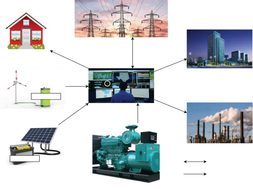
renewable energy resources/sources (RERs/RES) is more which are available across the globe. With the new policies, small power producers and renewable energy generation have been encouraged to meet the energy demand. In this case, the renewable generation can be much closer to the load and named as distributed generation. It saves the transmission resources, as well as losses, which are very less. Figure 1.1 shows the concept of distributed generation (DG) in modern power systems [2].
With the focus on renewable energy sources for electricity generation, a lot of research and advancement is going in this field and this results in reduced cost and increased efficiency of these systems. This makes RERs capable to meet the small as well as large energy demands of the customers. On the other hand, if we are considering the case of solar photovoltaic (PV) and wind, which are the main resources of renewable energy generation in India, they are highly dependent on environmental conditions like solar radiation and wind speed. Due to this, the output of these sources is not continuous, i.e., intermittent in nature which limits their use. If we consider the example of PV generation, it is high in the daytime and reduces at the evening hours, which may not meet the load demand. Renewable energy resources provide
Figure 1.1 Distributed generation in power system.
a provision for clean and green energy and can be integrated with the grid or used as a stand-alone unit. But the problem associated with renewable energy resources is that these are random and uncertain, which causes issues in electricity output. So, these can’t be used beyond a limit due to highly fluctuating output which causes power quality issues and makes the grid unstable and unsafe [3]. Secondly, the consumption rate of energy is not constant or fixed, it is varying with time so sometimes the availability of energy is surplus and sometimes there is a shortage; both conditions are undesirable.
Several issues like power system transients and dynamics, steady-state analysis, automatic generation control, voltage profile, active and reactive power control, spinning reserve, low voltage ride through, unit commitment and transmission curtailment, etc., are faced and for the stable and secure operation of the modern power system, these issues should be resolved. For a demand-supply balance and previously mentioned issues in modern power systems, energy storage methods are presented by the researchers.
The application of energy storage systems (ESSs) has been identified as a possible solution to compensate for the challenges faced by the modern electric power system. ESSs are in urgent demand by the conventional power generation industry, DERs, and intermittent renewable energy supply systems as they can offer required ancillary support and flexibility to them. Energy storage does not mean just the energy sources but they also provide the added benefits of improving reliability, stability, and also the quality of the power supply [4]. They are suitable for large (GW), medium (MW), or micro (kW) scale applications of the electric power system, depending on the task and requirement. They can be utilized for power demand balance, energy arbitrage, and reserve at the generation side; for investment deferral and frequency regulation at transmission level; for grid capacity support and voltage control at the distribution side; and for cost management and for peak shaving, etc., at the customer-side [5]. Thus, ESS is a necessary component and plays a key role in mitigating a wide range of operational challenges faced by the modern electric power system.
The main objective of this chapter is to give basic knowledge about energy storage systems. The reader will get familiar with different types of ESS and their applications in modern power systems whether it is the grid, microgrid or distribution generation domain, or grid integrated/stand-alone mode. The next section introduces different energy storage technologies (ESTs) including their types, benefits, and shortcomings. Several energy storage methods are available in the literature and can be used depending on the feasibility of the technique. A lot of work has been carried out by the researchers on energy storage systems and it is presented in this chapter with their pros and cons, and their characteristics in tabular form.
1.1.1 Basic Components of Energy Storage Systems
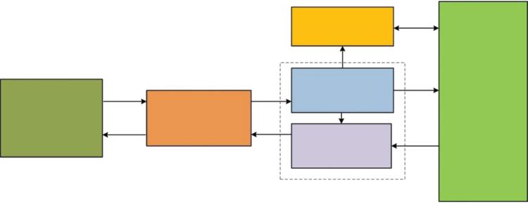
In AC power system, the electrical energy cannot be stored electrically. However, the AC energy can be stored by converting it into other energy forms such as kinetic, electromagnetic, electrochemical, or potential energy. Thus, a power conversion unit (PCU) is usually required by every energy storage technology to import electricity from the power grid and converting into a form that could be stored. The PCU converts it back to electricity during hours of peak demand or as when needed. Figure 1.2 demonstrates the main components of the ESS, which are as follows [6]:
i. Storage Medium: This provides the means to store energy for later use; such as the battery, PHES, flywheel energy storage system (FESS), capacitive/super-capacitive energy storage (CES/SCES), thermal energy storage (TES), compressed air energy storage (CAES), and superconducting magnetic energy storage (SMES).
ii. Control: It manages the functioning of the entire energy storage system and acts as a brain of the ESS.
iii. Charging: The charging unit facilitates the flow of energy from the electrical system to the energy storage medium.
iv. Discharging: It allows the flow of stored energy from the storage medium to the load when required.
1.2 Types of Energy Storage Systems
The issues and opportunities related to the RES encourage the researchers to provide reliable and efficient solutions in the form of ESS that have the capability to store and deliver energy when required. In addition to this,
Figure 1.2 Main components of an ESS [6].
ESS helps in maintaining power quality, load demand, grid stability, loss reduction, voltage and frequency regulation, energy efficiency improvement, reduction in fossil fuel usage, and protecting the environment from greenhouse gas emission and global warming [7, 8].
Electrical energy is not stored in its original form, but it can be converted to other forms of energy like chemical, mechanical, electrochemical, or thermal energy and can be stored (except electrostatic and electromagnetic storage, which are considered as electrical ESS) [9]. Some of the energy conversion techniques are as follows [10]:
a. Stored in the form of gravitational potential energy as a water reservoir.
b. In the form of compressed air
c. In the form of electrochemical energy using batteries
d. In the form of chemical energy by using fuel cells
e. In the form of kinetic energy using the flywheel
f. In the form of magnetic field using inductors
g. In the form of an electric field using a capacitor
h. In the form of thermal energy using sensible, latent, and chemical heat
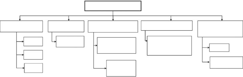
In energy storage systems, energy is stored when it is surplus or it is in excess as compared to load and this stored form of energy is converted into electrical energy when there is a lack of energy using power conversion systems (PCS). Figure 1.3 shows different types of energy storage techniques that are reported in the literature.
1.2.1 Chemical Energy Storage System
In a chemical energy storage system, energy stored in the chemical bonds of a compound is used. In every chemical reaction, energy is released or absorbed by the reaction. In some reactions when chemical bonds break, a large amount of energy is released that can be used for electricity production.
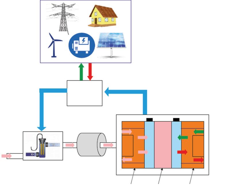
Hydrogen is a good alternative at present for the reduction in fossil fuel. It is abundant in nature and the simplest element. Due to these merits, now hydrogen ESS (HESS) is a well-known method for storing chemical energy. In this technique, the process of water electrolysis is started when there is excess availability of electrical energy and produced hydrogen is stored in storage tanks. When it is required to supply the energy back to the grid or for any other application at that instant, the oxidation process of hydrogen
Mechanical
FES
CAES Fuel cell and Electrolyzer
PHES
Energy Storage Systems
BESS: Li-ion, LA, NaS, Ni-Cd, VRLA
Sensible-TES, LatentTES, ThermochemicalTES, pumped-TES SMES
Flow BESS: Redox flow Hybrid flow
1.3 Different types of energy storage systems.
Ultra-capacitor, Supercapacitor
is started and electrical energy is generated from stored hydrogen. For this purpose, the setup uses a fuel cell or regenerative fuel cell to produce electrical energy from hydrogen [11] as depicted in Figure 1.4.
The chemical reaction which takes place during this conversion is [12] 2H2 + O2 → 2H2O
+ Energy Produce
Figure 1.4 Chemical/Fuel cell or Hydrogen energy storage system.
Figure
The components of this storage system are electrolyzer, fuel cell, hydrogen storage, and power conversion system to produce electricity. The electrolyzer is the main part that is responsible for water decomposition in hydrogen and oxygen. The hydrogen produced in this process is then stored. When there is a requirement of electrical energy then fuel cells reverse this process and released energy is converted into electrical energy.
Based on the type of electrolytes or fuel used, fuel cells can be classified as polymer electrolyte membrane fuel cell (PEMFC), alkaline fuel cell (AFC), phosphoric acid fuel cell (PAFC), molten carbonate fuel cell (MCFC), solid oxide fuel cell (SOFC) and direct methanol fuel cell (DMFC) [12, 13]. The advantage of HESS is no pollution, depth of discharge (DoD) up to 100%, no or very less self-discharge rate (depends upon the type of storage). Low efficiency (40-50%), high setup cost, and low security are the disadvantages of HESS [14].
1.2.2 Mechanical Energy Storage System
It is a commonly used, effective, and sustainable solution for energy storage. In a mechanical energy storage system (MESS), electrical energy is stored in mechanical form like potential energy, kinetic energy, or in the form of pressure. In MESS, three types of storage need to be discussed: pumped hydro storage, flywheels, and compressed air technique.
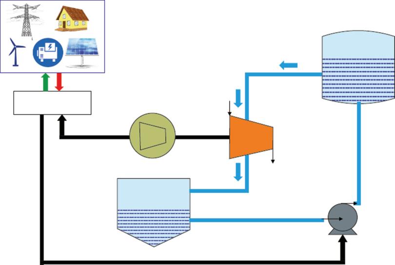
a. Pumped Hydroelectric Energy Storage
In pumped hydroelectric storage power plants, gravitational potential energy of water is used. In this storage system, there are two water reservoirs which are situated at different heights [15]. When there is excess energy generation than demand at that time the water pump is used to charge or store the water from the lower reservoir to the upper reservoir. In other case, when electrical energy is required then the discharging process is used. During discharging, water is released from the upper reservoir and it strikes turbine blades and turbine feed electrical energy into the system [16]. The schematic of the pumped hydroelectric storage system is shown in Figure 1.5.
The energy (E) production equation is E = mgh where m is the mass of water in kilogram (kg), g is the gravitational force and h is the head or the difference in height of two reservoirs in meter.
Pumped hydro storage technologies are a very old method and a very popular one as it is used in large-scale storage.
As an old and matured technology, it has advantages like its per-unit cost is low, large storage capacity, the life of the system is long, and its quick response time. But there are some drawbacks of this technology, such as high initial cost, large setup time, and highly dependence on geographical area.
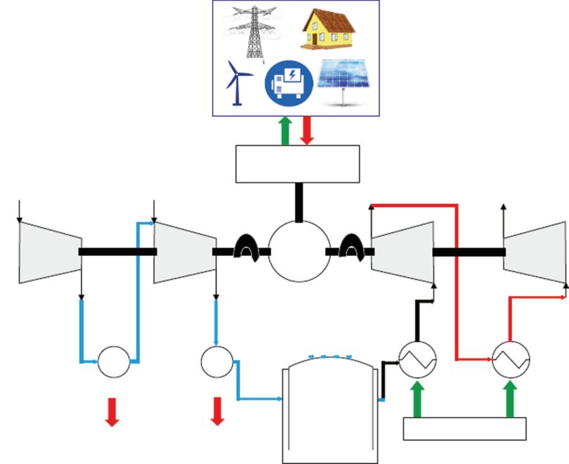
b. Compressed Air Energy Storage
CAES is also used for large-scale energy storage systems but these are not much wider. This storage system is similar to the gas turbine system as shown in Figure 1.6. In this storage system, the air is compressed and stored at high pressure in underground storage tanks. In the charging case, the compressor is driven by the motor, and air is stored. While in the discharging case, stored air is heated and released to the high-pressure turbine which is coupled with a generator and produces electrical power [17].
There are different types of CAES like advance adiabatic CAES, liquid air energy storage, supercritical CAES, Isothermal CAES, under-water CAES [18]. The merits of CAES are large-scale storage, high discharge rate and fast response, and while it causes pollution due to combustion and efficiency, that is highly dependent on the type of technique.
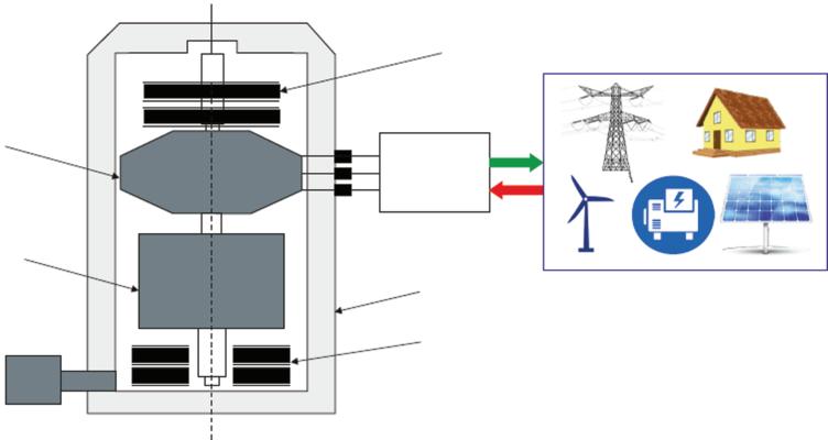
c. Flywheel Energy Storage
The flywheel is another mechanism to store the energy in mechanical form. It stores energy in the form of the angular momentum of a heavy rotating
Figure 1.5 Pumped hydroelectric storage system.
disk [19]. This technology is very much matured and old, as it is used in internal combustion engines. In the charging cycle, the flywheels store the energy in heavy mass by increasing the rotation speed through a motor. The stored energy depends upon the speed of the flywheel. When electrical energy is required then the discharging process starts. The stored mechanical energy is converted into electrical energy using a generator. The main components in grid-integrated mode of the flywheel energy storage system are shown in Figure 1.7.
The stored energy (E) is given as
where J is moment of inertia and ω is the angular velocity.
where m is the mass and r is the radius of the flywheel.
Figure 1.6 Compressed air storage system.
In mechanical systems, friction reduces the performance of the systems. So, to increase the performance and reduce the friction, magnetic bearings are used and the whole arrangement is enclosed in a vacuum chamber to reduce aerodynamic effect [20]. Based on rotation speed FES can be classified as low-speed FES whose speed is less than 10000 rpm and high-speed FES whose speed is from 104 to 105 rpm.
Some of the key features of FESS are very fast response, quickly supply a large amount of power, long life cycle, and no impact on the environment. The self-discharge rate and the very large cost are the barriers to this technology.
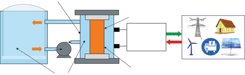
1.2.3 Electromagnetic Energy Storage System
In this type of storage system as shown in Figure 1.8, electrical energy is stored in the form of a magnetic field, which is created by passing a DC current to the large superconducting coil (niobium-titanium material). As superconductor phenomena exist at low temperatures, so here coil is cooled cryogenically at a lower temperature around -270°C. In the charging state magnitude of the current is increased while it is decreased in the discharging state. PCS controls the output of electrical energy as per the demand of the power system [21].
Figure 1.7 Flywheel storage system.
The stored energy in this storage system depends on the current and inductance of the coil and given as energy stored in the simple inductor as described by equation given below:
The electromagnetic energy storage system can be classified into two categories on the basis of temperature range [22]. First is low-temperature superconductor which is in the temperature range of -268°C or below. The second is high-temperature superconductors with a temperature range of higher than -268°C. This type of storage has advantages of very high efficiency, high power capacity, and long life cycle while high cost and effects due to strong magnetic field are issues associated with it.
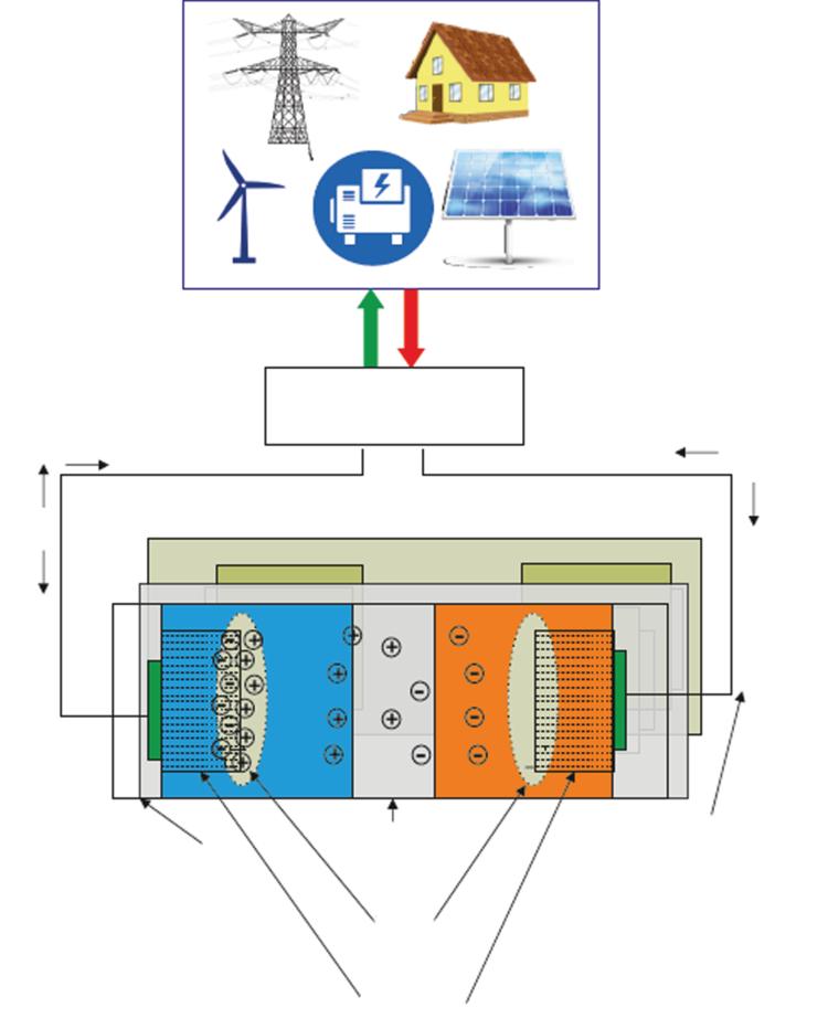
1.2.4 Electrostatic Energy Storage System
In electrostatic ESS, the storage of energy is done in the form of an electric field. For this purpose special type of capacitor which is called a double-layer capacitor (DLC) or ultra-capacitor, is used [23] as illustrated in Figure 1.9. In this special type of capacitor design, two separate electrodes are used which are porous and a separator is inserted in between these electrodes for storage of energy in the form of the electrostatic form [24].
The energy storage capacity is given by the simple capacitor equation as given below:
Figure 1.8 Electromagnetic energy storage system.
Many Batteries connected in series/ Parallel Separator Double Layer
As it is evident from the equation, storage energy depends on the capacitance of the capacitor and the square of the voltage across it.
The very fast response time in milli-seconds, very long life span, and high efficiency are the key features of this technology. Operating temperature limits, high cost, and low energy density are the challenges.
There is no chemical reaction that takes place in the electrostatic and electromagnetic techniques. Further in both these storage systems energies are stored in electrical form, so these two techniques are also known as an electrical energy storage system.
Porous Electrodes
Insulator shell
Figure 1.9 Electrostatic/supercapacitor energy storage system.
1.2.5 Electrochemical Energy Storage System
Electrochemical energy storage is the most popular form of energy storage nowadays. In this system, there is a conversion of chemical energy to electrical energy and vice versa. Batteries are of two types, the first one is primary batteries and the other is secondary batteries. Primary batteries can’t be reused, while secondary batteries can be reused after charging. Electrochemical energy storage batteries are secondary storage devices [25]. A generalized diagram for the basic structure of the battery is illustrated in Figure 1.10.
A battery consists of multiple cells and each cell consist of two electrodes, i.e., anode and cathode, submerged in an electrolyte. When an electrical load is connected to these electrodes externally flow of electron takes
Figure 1.10 Generalized diagram of batteries.
place in the closed path from one electrode to another electrode through load and electrolyte. The terminal voltage of each cell is near about 2 V and these are connected in series/parallel configuration to get the desired voltage and current level. The batteries can be further categorized based on electrolyte and electrodes and are discussed below.
a. Lead-acid battery
Lead-acid battery (LAB) is cheaper technology and mostly uses secondary battery which was invented in 1859. LAB consists of two electrodes and electrolytes namely Pb, PbO2, and H2SO4. In LAB chemical reaction takes place while charging and during discharging [26].
Pb + PbO2 + 2H2SO4 ↔ 2PbSO4 + 2H2O
The operating temperature range is -50C and 400C. The drawback of the LAB is its longer charging time and its size and weight as compared to other batteries and also the life cycle of the LAB is short. In spite of all these drawbacks LAB is frequently used for uninterrupted power supply application.
b. Nickel-cadmium battery
The positive electrode of this battery is made up of nickel hydroxide or nickel oxide hydroxide and a negative electrode is cadmium or cadmium hydroxide, while potassium hydroxide is used as electrolyte [2, 8]. The terminal voltage is about 1.2 volt. The chemical reaction takes place inside the battery
The advantage of Ni-Cd batteries is their high-power density and high efficiency along with less internal resistance. Its charging and discharging cycle is fast. Toxicity and high cost are the major disadvantage of this storage technology.
c. Sodium-sulfur battery
This battery is made from non-poisonous and less expensive material. It operates at a higher temperature of about 3000C. Sodium-sulfur battery is different from others since it utilizes solid electrolytes and electrodes in the molten phase. Molten sodium and molten sulfur are used as an electrode. While in the discharge process electrons release from sodium metal and the sodium ion moves to the positive electrode through the electrolyte [27]. 2Na + 4S ↔ Na2S4
2NiOOH + Cd + 2H2O ↔ 2Ni(OH)2 + Cd(OH)2
The high operating temperature and pure sulfur are risky since it can catch fire when it comes in contact with air or moisture.
d. Lithium-ion (Li-ion) battery
This battery is the most commonly used in low power consumption devices such as portable electronic devices or mobile phones. In a Li-ion battery cathode is made up of lithium metal or lithium compound. The anode is made up of graphite carbon material and the electrolyte used is lithium salt. The terminal voltage of the Li-ion battery is about 3.6V [28].
It has energy density and power density of 100-200 Wh/kg, 1000-2000 W/kg, respectively. The advantage of this battery is its portability, lightweight, economical, and fast charging/discharging cycle. Despite this, the major disadvantage of the battery is its poor heat handling capability.
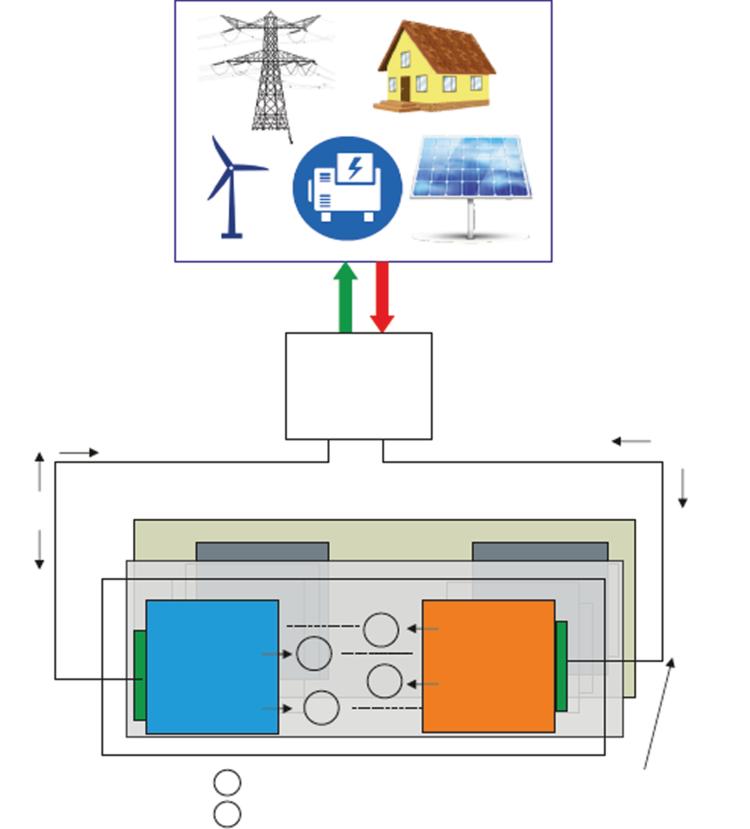
e. Flow battery energy storage system
These batteries are different from previously discussed secondary batteries as depicted in Figure 1.11. In this battery, two soluble electrolytes are stored in two different separable tanks which convert chemical energy to electrical energy by the electrochemical cell. The energy density of the flow battery depends on the size of the electrolyte tank whereas power density is based on the design of the cell. Flow battery can be classified as redoxoxidation (redox) flow battery and hybrid flow battery. In Redox flow battery, electroactive material is dissolved in a liquid electrolyte while in a hybrid one or more components are deposited. In a redox flow battery electroactive material is stored in separate tanks that circulate through pump [29].
Flow battery has few major advantages over other batteries as the capacity of this battery can be increased by increasing the size of the tank and the chemical and physical properties of electrode remain intact since it does not contain electroactive material due to which it gives stable and longer performance. Different kinds of flow batteries used in the power system are vanadium redox battery, zinc-bromine, and polysulfide bromine.
i. Vanadium redox battery
This type of battery uses V2+/V3+ ions at the negative electrode and V4+/ V5+ ions at the positive electrode. In the charging process, V3+ ions converted in V2+ ion and V4+ ion converted in V5+ and energy is stored in the cell, while in case of discharge, this chemical energy gets converted into electrical energy. In the charging process, oxidation of vanadium, ion takes place and during the discharging process reduction of vanadium, ion takes place [30].
The energy density of the vanadium redox battery is 35-65Wh/kg and the power density of 75-150W/kg. The advantage of VRB is that