Basic Electrical and Instrumentation Engineering P. Sivaraman
Visit to download the full and correct content document: https://ebookmass.com/product/basic-electrical-and-instrumentation-engineering-p-siv araman/
More products digital (pdf, epub, mobi) instant download maybe you interests ...
Basic Electrical And Instrumentation Engineering 1st Edition S. Salivahanan
https://ebookmass.com/product/basic-electrical-andinstrumentation-engineering-1st-edition-s-salivahanan/
Basic Electrical Engineering 3rd Edition Ravish R. Singh
https://ebookmass.com/product/basic-electrical-engineering-3rdedition-ravish-r-singh/
Basic Electrical, Electronics and Measurement Engineering 1st Edition S. Salivahanan
https://ebookmass.com/product/basic-electrical-electronics-andmeasurement-engineering-1st-edition-s-salivahanan/
Basic Electrical and Electronics Engineering-II (WBUT-2016) 5th Edition Abhijit Chakrabarti
https://ebookmass.com/product/basic-electrical-and-electronicsengineering-ii-wbut-2016-5th-edition-abhijit-chakrabarti/
Polymer Composites for Electrical Engineering Xingyi
Huang
https://ebookmass.com/product/polymer-composites-for-electricalengineering-xingyi-huang/
Principles and Applications of Electrical Engineering
7th Edition Giorgio Rizzoni
https://ebookmass.com/product/principles-and-applications-ofelectrical-engineering-7th-edition-giorgio-rizzoni/
Principles and Applications of Electrical Engineering
7th Edition Giorgio Rizzoni
https://ebookmass.com/product/principles-and-applications-ofelectrical-engineering-7th-edition-giorgio-rizzoni-2/
Principles And Applications Of Electrical Engineering
4th Edition Giorgio Rizzoni
https://ebookmass.com/product/principles-and-applications-ofelectrical-engineering-4th-edition-giorgio-rizzoni/
Fundamentals of Electrical Engineering 2nd Edition
Giorgio Rizzoni
https://ebookmass.com/product/fundamentals-of-electricalengineering-2nd-edition-giorgio-rizzoni/
Basic Electrical and Instrumentation Engineering
Scrivener Publishing
100 Cummings Center, Suite 541J Beverly, MA 01915-6106
Publishers at Scrivener
Martin Scrivener (martin@scrivenerpublishing.com)
Phillip Carmical (pcarmical@scrivenerpublishing.com)
Basic Electrical and Instrumentation Engineering
Sivaraman, C. Sharmeela, A. Thaiyal Nayagi, and R. Mahendran
P.
This edition first published 2021 by John Wiley & Sons, Inc., 111 River Street, Hoboken, NJ 07030, USA and Scrivener Publishing LLC, 100 Cummings Center, Suite 541J, Beverly, MA 01915, USA © 2021 Scrivener Publishing LLC
For more information about Scrivener publications please visit www.scrivenerpublishing.com.
All rights reserved. No part of this publication may be reproduced, stored in a retrieval system, or transmitted, in any form or by any means, electronic, mechanical, photocopying, recording, or otherwise, except as permitted by law. Advice on how to obtain permission to reuse material from this title is available at http://www.wiley.com/go/permissions.
Wiley Global Headquarters
111 River Street, Hoboken, NJ 07030, USA
For details of our global editorial offices, customer services, and more information about Wiley products visit us at www.wiley.com.
Limit of Liability/Disclaimer of Warranty
While the publisher and authors have used their best efforts in preparing this work, they make no representations or warranties with respect to the accuracy or completeness of the contents of this work and specifically disclaim all warranties, including without limitation any implied warranties of merchantability or fitness for a particular purpose. No warranty may be created or extended by sales representatives, written sales materials, or promotional statements for this work. The fact that an organization, website, or product is referred to in this work as a citation and/or potential source of further information does not mean that the publisher and authors endorse the information or services the organization, website, or product may provide or recommendations it may make. This work is sold with the understanding that the publisher is not engaged in rendering professional services. The advice and strategies contained herein may not be suitable for your situation. You should consult with a specialist where appropriate. Neither the publisher nor authors shall be liable for any loss of profit or any other commercial damages, including but not limited to special, incidental, consequential, or other damages. Further, readers should be aware that websites listed in this work may have changed or disappeared between when this work was written and when it is read.
Library of Congress Cataloging-in-Publication Data
ISBN 9781119764465
Cover image: Courtesy of the Authors
Cover design by Kris Hackerott
Set in size of 11pt and Minion Pro by Manila Typesetting Company, Makati, Philippines
Printed in the USA
10 9 8 7 6 5 4 3 2 1
Dedications
Mr. P. Sivaraman dedicating to his father Mr. A. Palanisamy (deceased), mother Mrs. P. Valarmathi, sister Mrs. P. Shanmuga Priya, Spouse Mrs. A. Gowri and Daughter baby S. Aathira.
Dr. C. Sharmeela dedicating to her parents Mr. N.S.Chenniappan and Mrs. C. Kasturi, my brother Chandrasekar, Vanitha, Shakthi Chandrasekar, Subathra and my beloved friends for encouraging me and extending their full support in writing the book.
Ms. A. Thaiyal Nayagi dedicating to her mother A.Mariyayee, sister A. sujatha and my brother’s A.Azhagirisamy, A.saravanamani for their constant encouragement and support.
Mr. R. Mahendran dedicating to his father, mother and sister.
5.2
Foreword
The backbone of electrical engineering is the power system, and it is one of the first things that a student in EE needs to learn. There are quite a large number of text books for courses on basics of electrical and instrumentation; this one presents a very simple, concise and clean approach that should make the subject very easily accessible to students. It will be particularly useful for revision after class lectures, and self study.
The first chapter introduces the student to the basic concepts of AC and DC power, voltage, current and the main constituents of a power system. In the subsequent chapters, students are introduced to DC and AC machines, as well as the basic tenets of measurement and instrumentation in the context of power systems. Chapter 2 describes the construction and operation of single phase and three phase transformers, while Chapter 3 does the same for DC machines. Chapter 4 covers AC machines, both induction machines and synchronous machines. Chapter 5 provides a brief exposition on simple measuring instruments and their operation. This should serve as a useful first introduction to power systems, before referencing advanced literature.
The authors have nicely blended their academic foundation with some industrial insight to make this book relevant and direct. I commend them on their work.
Nandini Gupta Professor
Department of Electrical Engineering Indian Institute of Technology, Kanpur
Acknowledgements
First and foremost thanks to the Almighty for his everlasting love throughout this endeavor.
Mr. P. Sivaraman expresses his sincere thanks to Mr. Balaji Sriram, Research Scholar, IIT Kanpur, D. Sathiya Moorty, Research Scholar, IIT Ropar, Mr. Upendran, Research Scholar, IIT Madras; Mr. Priyaranjan Satpathy, Research Scholar, ITER, SOA Deemed to be University, Bhubaneswar, Mr. S. Rajkumar, Executive, JLL, Bengaluru, Mr. K. Sasikumar, Electrical Engineer, Mott MacDonald, Noida, Mr. Muthukumaran, Director, TECH Engineering Services, Chennai, Mr. K. Balaji, Electrical Engineer, Sree Nandees Technologies, Chennai, Mr. Ravichandran, Andrew Yule and Dr. S. Logesh Kumar, Dean Electronics, Coimbatore for providing their technical support, figures, expert review and finalizing the contents.
Dr. C. Sharmeela expresses her sincere gratitude to her mentor Dr. D.P.Kothari, Former Director (i/c), IIT Delhi, her research supervisor
Dr. M.R.Mohan, Former Professor, Anna University, Chennai and Dr.S. Chandramohan, Professor & Head, DEEE, Anna University, Chennai for their continuous support and encouragement in completing this book.
Ms. A. Thaiyal Nayagi expresses her sincere thanks to the management of Rane polytechnic college, Dean, Principal and Head of the department of Mechanical and all staff members for their kind support and encouragement.
Mr. R. Mahendran expresses his sincere thanks to his friends and family members for their kind support and encouragement.
Introduction to Electric Power Systems
The main parameters in electrical systems are voltage and current. The product of voltage and current gives a third parameter called power, and power consumed over some time duration is called energy [1]. The electric power system consists of power generation, transmission and distribution system [2]. Power is generated from two main sources, namely conventional energy sources and non-conventional energy sources. The conventional energy sources are non-renewable which gets depleted over a period of time, while non-conventional energy sources are non-depleting sources [3, 10, 30]. Most large-scale power plants are located in areas where the raw materials are available locally and generated power is transmitted over long distances for distribution. An electrical conducting medium is required in order to transfer the power from generating station to load center. This conducting medium is called as transmission system. Transformers and transmission lines are the main components of the transmission system; they are used to transfer the power from generating station to consumers (customers) at various operating voltage levels. Generation voltage of the conventional power plant typically ranges from 6.6 kV to 22 kV, and transmission voltage typically ranges from 110 kV to 765 kV. High voltage is stepped down to various voltage levels for different consumers depending upon the requirements and installed capacity.
1.1 Introduction
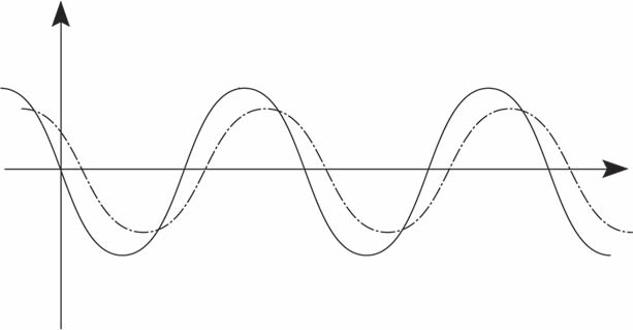
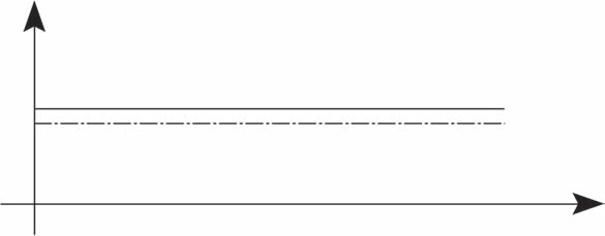
In general, electrical power used for commercial and residential purpose is mostly Alternating Current (AC). An AC voltage or current has the magnitude and direction which changes periodically with respect to time, unlike the Direct Current (DC) supply, which has constant magnitude with respect to time. Figure 1.1 shows the waveform of AC (voltage and current) and Figure 1.2 shows the waveform of DC (voltage and current).
P. Sivaraman, C. Sharmeela, A. Thaiyal Nayagi, and R. Mahendran. Basic Electrical and Instrumentation Engineering, (1–78) © 2021 Scrivener Publishing LLC
Types of AC supply system:
The AC supply system is classified into two types based on the number of phases:
• Single-phase power supply
• Three-phase power supply
A.
The single phase supply
The single-phase power supply is used to power all the single-phase loads in the systems. Generally, single-phase power supply is derived from a three-phase, four-wire circuit. The single-phase voltage level varies from country to country. The general single-phase supply voltage is 220 V, 230 V, 240 V in low voltage systems (in Asian countries). Most of the single-phase supply systems are 2W systems as shown in Figure 1.11.
Figure 1.1 Waveform of AC.
Figure 1.2 Waveform of DC.
B. Three-Phase Power Supply
The three-phase power supply is used to power certain loads which need the poly-phase supply for their operation. Here phase means branch circuits or winding and poly means many. Such loads in any applications need a power supply which has a poly-phase supply system. For example, three-phase power supply is also called poly-phase power supply. In order to develop poly-phase supply, the armature winding of an alternator is divided into the number of phases as required. In each winding section, voltage gets induced with 120° displacement. These windings are arranged in such a way that the magnitude and frequency is the same for all the phases with definite phase difference with respect to the other phases. That means, in a three-phase power supply system, there are three voltages with equal magnitude and frequency having a phase difference of 360°/3 = 120° between them.
Advantages of three-phase supply systems are
• Single-phase power supply are obtained from three-phase power supply and in reverse three-phase power supply is not obtained from single-phase power supply
• Three-phase induction motors are self-starting motors where single-phase induction motors are not self-starting motors
• For transmission and distribution, a three-phase system needs smaller size conductor material as compared with single-phase system for same volt amperes
1.1.1 Electrical Parameters
The main parameters in an electrical system are voltage and current. The product of voltage and current gives a third parameter called power, and power consumed over some duration is called energy.
AC systems: Voltage, Current, Frequency and Phase angle
DC systems: Voltage and Current
1.1.1.1
Voltage
Potential difference between any two points in an electrical circuit is called voltage. The SI unit of voltage is Volts (V) [1]. Higher values of voltage are mentioned as kV. The other name of voltage is Electro Motive Force (EMF). The representation of voltage is two types: peak to peak voltage (instantaneous voltage) and RMS voltage.
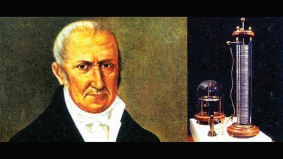
Volta (18th Feb 1745 – 5th March 1827): An Italian scientist who invented the first battery cell. In order to honour him, SI unit of electric potential is named Volt.
RMS voltage:
The peak to peak voltage of phase to phase is shown in Figure 1.3. Average voltage of positive half cycle to negative half cycle is zero. As the absolute voltage is not zero, average voltage cannot be used as a measuring scale for AC. In order to perform the analysis and calculation, a new term called RMS is considered for measurement. Theoretically, RMS voltage in AC is equivalent to the amount of heat produced if the DC of some magnitude produces the same heat on the same resistance.
Generally, most of voltage referred in specification is RMS voltage unless specified.
Example 1.1: A 40 W incandescent lamp is connected across 1ɸ, 230 V, 50 Hz AC supply.
Here the voltage 230 V is RMS voltage.
Note: When using the multi meter for voltage measurements, first check the meter is RMS rated or peak rated in order to avoid confusion. For an example, if RMS rated meter read the voltage as 230 V, the peak rated meter will read the same voltage as 325.2 V.
RMS voltage from peak voltage:
RMS voltage can be calculated if peak voltage is known. The expression for RMS voltage is given in eqn. 1.1.
Alessandro
Alessandro Volta. Courtesy: Google image.
12:29:59.850 22-04-2015 Wednesday 12:29:59.855 12:29:59.860 12:29:59.865 12:29:59.870
Figure 1.3 Peak to peak voltage of R phase to Y phase. Note: This figure is captured using Dranetz Power Quality analyser.
VoltageRMS VoltagePeak CrestFactor () () = (1.1)
For sinusoidal wave shape, the value of crest factor is 2 .
Example 1.2: A sinusoidal supply voltage is 340 V peak. Calculate equivalent RMS voltage. Solution: VoltageRMS VoltagePeak () () == 2 340 2
Voltage (RMS) = 240.5 V is ~241 V.
Example 1.3: A sinusoidal supply voltage is 565 V peak. Calculate equivalent RMS voltage.
Solution: VoltageRMS VoltagePeak () () == 2 565 2
Voltage (RMS) = 399.6 V is ~400 V.
Peak voltage from RMS voltage:
Peak voltage can be calculated if RMS voltage is known. The expression for peak voltage is given in eqn 1.2.
Voltage (Peak) = Voltage (RMS) X Crest Factor (1.2)
Example 1.4: A sinusoidal supply voltage is 240 V (RMS). Calculate equivalent peak voltage.
Solution:
VoltagePeakVoltage RMS () () =∗ =∗ 2 240 2
Voltage (Peak) = 339.3 V is ~ 339 V
Example 1.5: A sinusoidal supply voltage is 415 V RMS. Calculate equivalent peak voltage.
Answer:
VoltagePeakVoltage RMS () () =∗ =∗ 2 415 2
Voltage (Peak) = 586.8 V is ~ 587 V.
Peak to peak voltage:
Voltage measured between the maximum value of the positive half cycle and the minimum value of the negative half cycle is known as peak to peak voltage. This voltage is generally measured in individual voltage cycle, unlike the peak voltage which is the product of RMS voltage and crest factor measured in voltage trend. Peak to peak voltage of R to Y phase is shown in Figure 1.3.
The maximum voltage of positive half cycle of above waveform is 556.4 V and minimum voltage of negative half cycle of the waveform is 556.4 V. Voltage between positive half cycle to negative half cycle is +556.4 to -556.4 V is called peak to peak voltage. It is 1112.8 V in the above Figure 1.3. Figure 1.4 shows the peak voltage trend, which is different from peak to peak voltage.
From Figure 1.4, the peak voltage is between 555 V to 560 V for the time duration 70 minutes between 12:40 hours to 13:50 hours.
Voltage in three-phase circuit:
Voltage in a three-phase circuit is determined based on the system configuration. The determination of voltage in a circuit is based on whether the circuit is in star or delta configuration.
Figure 1.4 Peak voltage trend. Note: This figure is captured using Dranetz Power Quality analyser.
1. Phase to phase voltage – For delta circuits
2. Phase to neutral voltage – For star circuits
The relationship between the above two voltage determinations is expressed in the equation (1.3) and (1.4).
In delta circuit, the phase voltage is determined by Voltage Voltage Ph Line = 3
In star circuit, the line voltage is determined by
Voltage Line Ph = 3
Where
VoltageLine is line voltage
VoltagePh is phase voltage
In delta circuit, line current in delta circuit is greater than line current in star circuit. Similarly, the line voltage in star circuit is greater than line voltage in delta circuit. 12:40 22-04-2015 Wednesday 12:50 13:00 13:1013:20 13:3013:40 13:50
A-B VPeak (val)
Example 1.6: A distribution transformer of 2 MVA power rating Dyn11 configuration is having ratio of 11 kV/433 V. How do we understand this voltage?
Answer:
A distribution transformer is generally used to cater single-phase loads connected on three-phase distribution. This is the reason the secondary side of the transformer is star with neutral in the circuit. The primary side of the transformer is delta. 11 kV at primary side means phase to phase voltage across RY, YB and BR. 433 V secondary corresponds to 250 V between RN, YN and BN while 433 V could be recorded between RY, YB and BR.
The phase to phase voltage is voltage between any of two phases (R to Y, Y to B or R to B). It can either be RMS voltage or peak voltage and it is applicable to three-phase 3wire and three-phase 4wire circuits. The threephase 4wire, 415 V, 50 Hz AC circuit is shown in Figure 1.5.
Example 1.7: What is the voltage between R to Y phase in Figure 1.5?
Answer: 415 V.
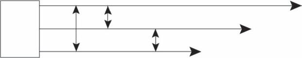
The three-phase 3W, 11 kV, 50 Hz AC circuit is shown in Figure 1.6.
Example 1.8: What is the voltage between Y to B phase in Figure 1.6?
Answer: 11 kV.
In India, the transmission voltages are 11 kV, 22 kV, 33 kV, 66 kV, 110 kV, 132 kV, 220 kV, 230 kV, 400 kV and 765 kV and the distribution voltage is
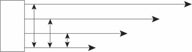
Three phase, 50 Hz, 415 V AC supply
Figure 1.5 Three-phase, Four-wire circuit configuration.
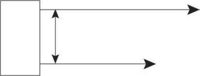
Three phase, 50 Hz, 11 kV AC supply
Figure 1.6 Three-phase, Three-wire circuit configuration.
415 V. All the above-mentioned voltages are phase to phase voltage only. Similar voltage levels are used in other countries in the world.
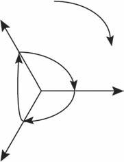
The three-phase power supply system has three voltages with equal magnitude, frequency and displaced by 120° each other. That means, the phase angle difference between three phases is 120 electrical degrees. The vector displacement of three-phase voltage is shown in Figure 1.7.
The three-phase voltages are denoted as eR, eY eB, and their expression are given below
eR = Emsin (ωt)
eY = Emsin (ωt - 120°)
eB = Emsin (ωt + 120°) = Emsin (ωt - 240°)
As Phasor rotates in anti-clockwise direction, voltage eY lags eR by 120° and eB lags eR by 240°.
The phase angle displacement of three-phase voltage wave shape is shown in Figure 1.8.
The voltage displacement between the phases should be 120 electrical degrees. 360 electrical degrees equal to 20.066 milli seconds from Figure 1.8. Corresponding electrical degree for 6.793 milli seconds is worked out as 121.8 electrical degrees. Figure 1.9 shows the angular separation between three phases. Y phase voltage lags R phase by 120.938° similarly B phase lags Y phase 120.938°. Figure 1.8 and Figure 1.9 represent the phase angle displacement in time domain and angular domain form, respectively.
Line to neutral voltage is voltage between any one of the line to neutral. This voltage is applicable where neutral conductor is also a return current carrying conductor in the circuit like in three-phase four-wire circuit and single-phase two-wire circuit. Low voltage distribution system uses the
1.7 Vector displacement of three phases.
Figure
10 Basic Electrical and Instrumentation Engineering
20:06:29.855 17-08-2016 Wednesday 20:06:29.860 20:06:29.865 20:06:29.870 20:06:29.875 20:06:29.880
Figure 1.8 Phase angle displacement of three-phase voltage waveform in time domain. Note: This figure is captured using Dranetz Power Quality analyser.
Figure 1.9 Phase angle displacement of three-phase voltage waveform in angular form. Note: This figure is captured using Dranetz Power Quality analyser.
Introduction to Electric Power Systems 11
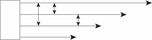
neutral for single-phase loads. The three-phase, four-wire, 415 V, 50 Hz AC circuit is shown in Figure 1.10.
Example 1.9: What is the voltage between R phase and neutral in Figure 1.10?
Answer: from eqn. 1.4, R phase and neutral voltage is 240 V.
The single-phase, two-wire AC circuit is shown in Figure 1.11.
Example 1.10: What is the voltage between R phase and neutral in Figure 1.11?
Answer: 240 V.
1.1.1.2 Current
Current is rate of flow of electric charge across the potential difference in a closed electric circuit. The current flows from high voltage to low voltage in the closed circuit [1]. The SI unit of current is Ampere (A). Higher values of current are mentioned as kA.
Andre Marie Ampere (20th Jan 1775 – 10th Jun 1836): A French scientist discovered the science of classical electromagnetism and electrodynamics. In order to honour him, SI unit of electric current is his name, Ampere.
Andre Marie Ampere. Courtesy: Google image.
Three phase, 50 Hz, 415 V AC supply
Neutral B phase to Neutral Y phase to Neutral R phase to Neutral
Figure 1.10 Three-phase, four-wire circuit configuration.
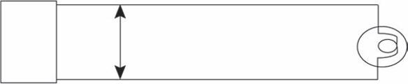
Single phase, 50 Hz, 240 V AC supply
Phase to neutral voltage
Figure 1.11 Single-phase, two-wire system.
Neutral
Phase
Single phase, 50 Hz, 240 V AC supply P N
Phase to neutral voltage
40 W bulb
Figure 1.12 40 W bulb connected across 240 V supply.
Single phase, 50 Hz, 240 V AC supply P N
Phase to neutral voltage
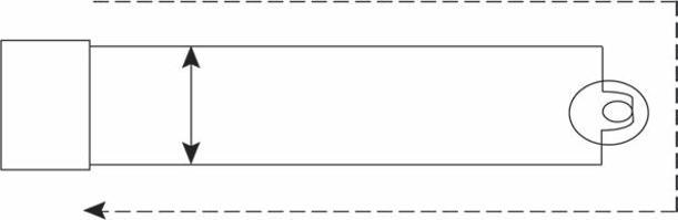
Figure 1.13 Direction of current flow for positive half cycle.
40 W bulb
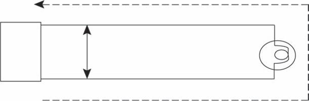
A single-phase, two-wire AC circuit is shown in Figure 1.12.
The current flow direction for positive half cycle is represented as dotted line in Figure 1.13.
The current flow direction for negative half cycle is represented as dotted line in Figure 1.14.
The factor which decides the value of current flow in the circuit is load impedance.
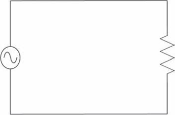
Example 1.11: A 5 Ω resistance (load) is connected across a single-phase 230 V, 50 Hz AC supply is shown in Figure 1.15. Calculate the current drawn by 5Ω resistance.
Solution:
Theoretical calculation: Current drawn by the load resistance of 5 Ω is theoretically calculated by Ohms law [31].
W bulb Phase to neutral voltage
1φ, 50 Hz, 230 V AC supply 5 Ω
1.15 Circuit diagram of single-phase AC supply feeding R Load.
Figure 1.14 Direction of current flow for negative half cycle.
Figure
14 Basic Electrical and Instrumentation Engineering
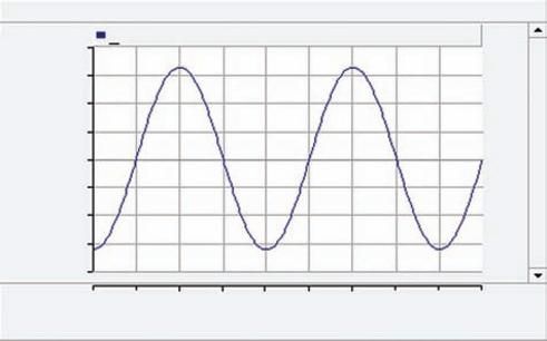
Simulation result:
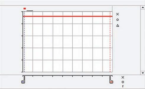
The instantaneous current (IL) wave shape drawn by the load and RMS current trend are shown in Figure 1.16 and Figure 1.17, respectively. The current in RMS value of a Sine wave from simulation is 0.046 kA or 46 A. i.e,
George Simon Ohm (16th March 1789 – 6th July 1854): A German scientist discovered direct proportionality between the potential difference applied across a conductor and the resultant electric current. This relationship is called Ohm’s law. In order to honour him, SI unit of electric resistance is in his name. Ohm.
1.16
1.17
Figure
Current wave shape in kA.
Figure
RMS current trend in kA.