FIBER-OPTIC COMMUNICATION SYSTEMS
FifthEdition
GovindP.Agrawal
TheInstituteofOptics
UniversityofRochester Rochester,NY
Thiseditionfirstpublished2021 ©2021JohnWiley&Sons,Inc.
EditionHistory
JohnWiley&Sons,Inc.(4e,2010)
JohnWiley&Sons,Inc.(3e,2002)
JohnWiley&Sons,Inc.(2e,1997)
JohnWiley&Sons,Inc.(1e,1993)
Allrightsreserved.Nopartofthispublicationmaybereproduced,storedinaretrievalsystem,ortransmitted,inanyform orbyanymeans,electronic,mechanical,photocopying,recordingorotherwise,exceptaspermittedbylaw.Adviceonhow toobtainpermissiontoreusematerialfromthistitleisavailableat http://www.wiley.com/go/permissions
TherightofGovindP.Agrawaltobeidentifiedastheauthorofthisworkhasbeenassertedinaccordancewithlaw.
RegisteredOffice
JohnWiley&Sons,Inc.,111RiverStreet,Hoboken,NJ07030,USA
EditorialOffice 111RiverStreet,Hoboken,NJ07030,USA
Fordetailsofourglobaleditorialoffices,customerservices,andmoreinformationaboutWileyproductsvisitusat www .wiley.com
Wileyalsopublishesitsbooksinavarietyofelectronicformatsandbyprint-on-demand.Somecontentthatappearsin standardprintversionsofthisbookmaynotbeavailableinotherformats.
LimitofLiability/DisclaimerofWarranty
Thecontentsofthisworkareintendedtofurthergeneralscientificresearch,understanding,anddiscussiononlyandarenot intendedandshouldnotberelieduponasrecommendingorpromotingscientificmethod,diagnosis,ortreatmentbyphysiciansforanyparticularpatient.Inviewofongoingresearch,equipmentmodifications,changesingovernmentalregulations, andtheconstantflowofinformationrelatingtotheuseofmedicines,equipment,anddevices,thereaderisurgedtoreview andevaluatetheinformationprovidedinthepackageinsertorinstructionsforeachmedicine,equipment,ordevicefor, amongotherthings,anychangesintheinstructionsorindicationofusageandforaddedwarningsandprecautions.While thepublisherandauthorshaveusedtheirbesteffortsinpreparingthiswork,theymakenorepresentationsorwarranties withrespecttotheaccuracyorcompletenessofthecontentsofthisworkandspecificallydisclaimallwarranties,including withoutlimitationanyimpliedwarrantiesofmerchantabilityorfitnessforaparticularpurpose.Nowarrantymaybecreated orextendedbysalesrepresentatives,writtensalesmaterialsorpromotionalstatementsforthiswork.Thefactthatanorganization,website,orproductisreferredtointhisworkasacitationand/orpotentialsourceoffurtherinformationdoesnot meanthatthepublisherandauthorsendorsetheinformationorservicestheorganization,website,orproductmayprovide orrecommendationsitmaymake.Thisworkissoldwiththeunderstandingthatthepublisherisnotengagedinrendering professionalservices.Theadviceandstrategiescontainedhereinmaynotbesuitableforyoursituation.Youshouldconsult withaspecialistwhereappropriate.Further,readersshouldbeawarethatwebsiteslistedinthisworkmayhavechangedor disappearedbetweenwhenthisworkwaswrittenandwhenitisread.Neitherthepublishernorauthorsshallbeliablefor anylossofprofitoranyothercommercialdamages,includingbutnotlimitedtospecial,incidental,consequential,orother damages.
LibraryofCongressCataloging-in-PublicationData
Names:Agrawal,G.P.(GovindP.),1951-author.
Title:Fiber-opticcommunicationsystems/GovindP.Agrawal.
Description:Fifthedition.|Hoboken,NJ:Wiley,2021.|Includesbibliographical referencesandindex.
Identifiers:LCCN2021019319(print)|LCCN2021019320(ebook)|ISBN 9781119737360(cloth)|ISBN9781119737377(adobepdf)|ISBN 9781119737384(epub)
Subjects:LCSH:Fiberoptics.|Opticalcommunications.
Classification:LCCTA1800.A472021(print)|LCCTA1800(ebook)|DDC 621.382/75–dc23
LCrecordavailableathttps://lccn.loc.gov/2021019319
LCebookrecordavailableathttps://lccn.loc.gov/2021019320
CoverDesign:Wiley
CoverImage:©iStockphoto/GettyImages
Setin10/12ptTimesNewRomanMTStdbyStraive,Chennai,India
TothememoryofmyParents
ToAnne,Sipra,Caroline,andClaire
2.1Geometrical-OpticsDescription
2.1.1Step-IndexFibers
2.1.2Graded-IndexFibers
2.3.5Polarization-ModeDispersion
2.4Dispersion-InducedLimitations
2.6.1StimulatedLightScattering
3.1SemiconductorLaserPhysics
3.1.1SpontaneousandStimulatedEmissions
3.1.2NonradiativeRecombination
3.5.1LEDCharacteristics
4.2CommonPhotodetectors
4.2.2 p–i–n Photodiodes ....................................
4.2.3AvalanchePhotodiodes
4.2.4MSMPhotodetectors ..................................
4.3ReceiverDesign
4.3.1TheFrontEnd
4.3.2TheLinearChannel
4.3.3Data-RecoverySection
4.4.2SNRof p–i–n Receivers ................................
4.4.3SNRofAPDReceivers
4.5CoherentDetection .......................................
4.5.1LocalOscillator
4.5.2HomodyneDetection
4.5.3HeterodyneDetection
4.5.4Signal-to-NoiseRatio
5.1SystemArchitectures
5.1.1Point-to-PointLinks
5.2DesignGuidelines
5.2.1Loss-LimitedLightwaveSystems
5.2.2Dispersion-LimitedLightwaveSystems
5.2.3PowerBudget
5.2.4Rise-TimeBudget
5.3Long-HaulSystems
5.3.1Performance-LimitingFactors
5.3.2TerrestrialLightwaveSystems
5.3.3UnderseaLightwaveSystems
5.4SourcesofPowerPenalty
5.4.1ModalNoise
5.4.2Mode-PartitionNoise
5.4.3ReflectionFeedbackandNoise
5.4.4DispersivePulseBroadening
5.4.5FrequencyChirping
6.1WDMSystemsandNetworks
6.1.1High-CapacityPoint-to-PointLinks
6.1.2Wide-AreaandMetro-AreaNetworks
6.2.2MultiplexersandDemultiplexers
6.2.3Add–DropMultiplexers
6.2.4StarCouplers
6.2.5WavelengthRouters
6.3.3XPM-InducedNonlinearCrosstalk
6.3.4FWM-InducedNonlinearCrosstalk
6.4Time-DivisionMultiplexing
6.4.1Time-DomainMultiplexing
6.5.1AnalogandDigitalSCMSystems
6.6Code-DivisionMultiplexing
6.6.1Time-DomainEncoding
6.6.2Frequency-DomainEncoding
7.2.1PumpingandGainSpectrum
7.2.3AmplifierNoise
7.2.4MultichannelAmplification
7.3RamanAmplifiers ........................................
7.3.1RamanGainandBandwidth
7.3.2Raman-InducedSignalGain
7.3.3Multiple-PumpRamanAmplification
7.3.4NoiseFigureofRamanAmplifiers
7.4OpticalSignal-To-NoiseRatio
7.4.1LumpedAmplification
7.4.2DistributedAmplification
7.5ElectricalSignal-To-NoiseRatio
7.5.1ASE-InducedCurrentFluctuations
7.5.2ImpactofASEonSNR
7.5.3NoiseBuildupinanAmplifierChain
7.6ReceiverSensitivityand Q Factor ...............................
7.6.1Bit-ErrorRate ......................................
7.6.2RelationBetween Q FactorandOpticalSNR
7.7RoleofDispersiveandNonlinearEffects
7.7.1NoiseGrowthThroughModulationInstability
7.7.2Noise-InducedSignalDegradation
7.7.3Noise-InducedEnergyFluctuations
7.7.4Noise-InducedTimingJitter
7.8PeriodicallyAmplifiedLightwaveSystems
8.4Dispersion-EqualizingFilters
8.4.1Gires–TournoisFilters
8.4.2Mach–ZehnderandOtherFilters
8.5OpticalPhaseConjugation
8.5.1PrincipleofOperation
8.6.1TunableDispersionCompensation
8.7.1Pre-compensationattheTransmitter
9.2SolitonsinOpticalFibers
Preface
Sincethepublicationofthefirsteditionofthisbookin1992,thestateoftheartoffiber-optic communicationsystemshasadvanceddramaticallybetweenthefirstandfiftheditions.Thehighest capacityofcommercialfiber-opticlinksavailablein1992wasonly2.5Gb/s.Amerefouryearslater, withtheadventofwavelength-divisionmultiplexing(WDM),systemswiththecapacityof40Gb/s becameavailablecommercially.By2001,thecapacityofcommercialWDMsystemsexceeded 1.6Tb/s.Atthesametime,thecapacityoftransoceaniclightwavesystemsinstalledworldwide exploded.Aglobalnetwork(TGN-Pacific)covering250,000kmwithacapacityof2.56Tb/s (64WDMchannelsat10Gb/sover4fiberpairs),becameoperationalin2004,andthebitrateof eachchannelwasupgradedto100Gb/sby2014(ownedbyTataCommunicationsLimited).With theadventofcoherenttechnology,thecapacityofsubmarinesystemshasexploded.Forexample, thePacificLightCableNetwork(PLCN)thatbecameoperationalin2020(ownedbyGoogle andFacebook),isdesignedtocoveradistance12,900kmandtooperatewithatotalcapacity approaching144Tb/soversixfiberpairs.
Thefourtheditionofthisbookappearedin2010.Ithasbeenwellreceivedbythescientificcommunityinvolvedwithlightwavetechnology.Judgingfromthebook’sadoptionasatextbookfor coursesofferedattheuniversitiesworldwide,itappearsthattheeducationalcommunityalsolikes thisbook.Becauseoftherapidadvancesthathaveoccurredoverthelast10years,thepublisherand Ideemeditnecessarytobringoutthefiftheditiontoensurethatthebookcontinuestoprovidea comprehensiveandup-to-dateaccountoffiber-opticcommunicationsystems.Theresultisinyour hands.Theprimaryobjectiveofthebookremainsthesame.Specifically,itshouldbeabletoserve bothasatextbookandareferencemonograph.Forthisreason,theemphasisisonthephysical understanding,buttheengineeringaspectsarealsodiscussedthroughoutthetext.
Becauseofthelargeamountofmaterialthatneededtobeaddedtoprovidecomprehensivecoverage,thebooksizehasincreasedconsiderablycomparedwiththefirstedition.Althoughallchapters havebeenupdated,themajorchangeshaveoccurredinChapters10to12.Asbefore,Chapters1 to6providethebasicfoundation,whileChapters7to12coverthethedesignofadvancedlightwavesystems.Chapters7to9aredevotedtothetechniquesusedforthemanagementoffiber’s losses,itschromaticdispersion,anditsnonlinearity.Chapter10focusesonthecoherentsystems employingthephase-basedmodulationformats.Chapter11isdevotedtotheemergingtechnique ofspace-divisionmultiplexingmakinguseofmulticoreandmultimodefibers.Chapter12describes afewadvancedtopicsthatmaybecomepracticalinthenearfuture.Thecontentsofthebookreflect thestateoftheartofopticalcommunicationsystemsin2020.
Theprimaryroleofthisbookisasagraduate-leveltextbookinthefieldof opticalcommunications Anattemptismadetoincludeasmuchrecentmaterialaspossiblesothatstudentsareexposedto therecentadvancesinthisexcitingfield.Thebookcanalsoserveasareferencetextforresearchers alreadyengagedinorwishingtoenterthefieldofopticalfibercommunications.Thereferencelistat theendofeachchapterismoreelaboratethanwhatiscommonforatypicaltextbook.Thelistingof recentresearchpapersshouldbeusefulforresearchersusingthisbookasareference.Atthesame time,studentscanbenefitfromitiftheyareassignedproblemsrequiringreadingoftheoriginal
researchpapers.Asetofproblemsisincludedattheendofeachchaptertohelpboththeteacher andthestudent.Althoughwrittenprimarilyforgraduatestudents,thebookcanalsobeusedforan undergraduatecourseattheseniorlevelwithanappropriateselectionoftopics.Partsofthebook canbeusedforseveralotherrelatedcourses.Forexample,Chapter2canbeusedforacourseon opticalwaveguides,andChapters3and4canbeusefulforacourseonoptoelectronics.
ManyuniversitiesintheUnitedStatesandelsewhereofferacourseonopticalcommunications asapartoftheircurriculuminelectricalengineering,physics,oroptics.Ihavetaughtsuchacourse since1989tothegraduatestudentsoftheInstituteofOptics,andthisbookindeedgrewoutof mylecturenotes.Iamawarethatitisusedasatextbookbymanyinstructorsworldwide—afact thatgivesmeimmensesatisfaction.Iamawareofaproblemthatisasideeffectofanenlarged revisededition.Howcanateacherfitallthismaterialinaone-semestercourseon opticalcommunications?Ihavetostrugglewiththesamequestion.Infact,itisimpossibletocovertheentirebook inonesemester.Thebestsolutionistoofferatwo-semestercoursecoveringChapters1through6 duringthefirstsemester,leavingtheremainderforthesecondsemester.However,notmanyuniversitiesmayhavetheluxuryofofferingatwo-semestercourseonopticalcommunications.Thebook canbeusedforaone-semestercourseprovidedthattheinstructormakesaselectionoftopics. Forexample,Chapter3canbeskippedifthestudentshavetakenalasercoursepreviously.Ifonly partsofChapters7through11arecoveredtoprovidestudentsaglimpseoftherecentadvances,the materialcanfitinasingleone-semestercourse,offeredeitherattheseniorlevelforundergraduates ortograduatestudents.
Manypersonshavecontributedtothisbookeitherdirectlyorindirectly.Itisimpossibletomentionallofthembyname.Ithankmygraduatestudentsandthestudentswhotookmycourseon opticalcommunicationsystemsfortheirinsightfulquestionsandcomments.Thanksaredueto manyinstructors,whonotonlyhaveadoptedthisbookasatextbookbuthavealsopointedoutthe misprintsinpreviouseditions.IamgratefultomycolleaguesattheInstituteofOpticsfornumerous discussionsandforprovidingacordialandproductiveatmosphere.Last,butnotleast,Ithankmy familyforunderstandingwhyIneededtospendmanyweekendsonthebookinsteadofspending timewiththem.
Chapter1 Introduction
Acommunicationsystemtransmitsinformationfromoneplacetoanother,whetherseparatedbya fewkilometersorbytransoceanicdistances.Informationisencodedonanelectromagneticcarrier wave,whosefrequencycanvaryfromafewmegahertztoseveralhundredterahertz.Opticalcommunicationsystemsemployhighfrequencies(∼200THz)inthenear-infraredregionoftheelectromagneticspectrum.Theyarealsocalledlightwavesystemstodistinguishthemfrommicrowavesystems, whosecarrierfrequencyistypicallysmallerbyfiveordersofmagnitude(∼1GHz).Fiber-opticcommunicationsystemsarelightwavesystemsthatemployopticalfibersforinformationtransmission. Suchsystemshavebeendeployedworldwidesincetheyear1980andhaverevolutionizedthefieldof telecommunications.Indeed,lightwavetechnology,togetherwithmicroelectronics,ledtotheadvent ofthe“informationage”duringthe1990s.Thisbookdescribesfiber-opticcommunicationsystems inacomprehensivemanner.Theemphasisisonthefundamentalaspects,butrelevantengineering issuesarealsodiscussed.Inthisintroductorychapter,wepresentthebasicconceptsandprovide thebackgroundmaterial.Section1.1givesahistoricalperspectiveonthedevelopmentofoptical communicationsystems.Section1.1.2coversconceptssuchasanaloganddigitalsignals,channel multiplexing,andmodulationformats.Relativemeritsofvariouslightwavesystemsarediscussedin Section1.3.Thelastsectionfocusesonthebuildingblocksofafiber-opticcommunicationsystem.
1.1HistoricalPerspective
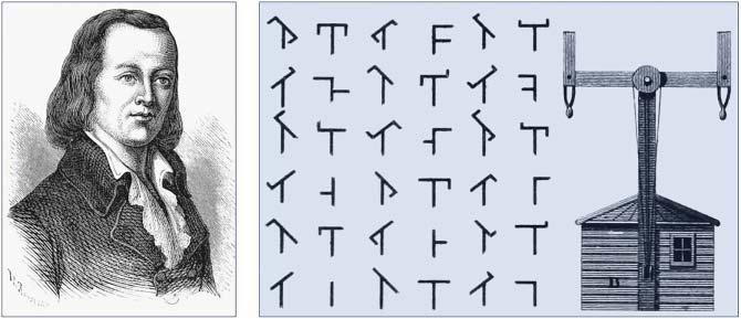
Theuseoflightforcommunicationpurposesdatesbacktoantiquityifweinterpretopticalcommunicationsinabroadsense[1].Mostcivilizationshaveusedmirrors,firebeacons,orsmokesignals toconveyasinglepieceofinformation(suchasvictoryinawar).Essentiallythesameideawas useduptotheendoftheeighteenthcenturythroughsignalinglamps,flags,andothersemaphore devices.Theideawasextendedfurther,followingasuggestionofClaudeChappein1792,totransmitmechanicallycodedmessagesoverlongdistances(∼100km)bytheuseofintermediaterelay stations[2],actingas regenerators or repeaters inthemodern-daylanguage.Figure1.1showsthe inventorandhisbasicideaschematically[3].Thefirstsuch“opticaltelegraph”wasputinservice betweenParisandLille(twoFrenchcitiesabout200kmapart)inJuly1794.By1830,thenetwork hadexpandedthroughoutEurope[1].Theroleoflightinsuchsystemswassimplytomakethe codedsignalsvisiblesothattheycouldbeinterceptedbytherelaystations.Theopto-mechanical
Fiber-OpticCommunicationSystems,FifthEdition.GovindP.Agrawal. ©2021JohnWiley&Sons,Inc.Published2021byJohnWiley&Sons,Inc.
Figure1.1: ClaudeChappe,hiscodingscheme,andthemechanicaldeviceusedformakingopticaltelegraphs. Source:Agrawal[3].
communicationsystemsofthenineteenthcenturywereinherentlyslow.Inmodern-dayterminology, theeffectivebitrateofsuchsystemswaslessthan1bitpersecond(B < 1b/s).
1.1.1NeedforFiber-OpticCommunications
Theadventoftelegraphyinthe1830sreplacedtheuseoflightbyelectricityandbegantheeraofelectricalcommunications[4].Thebitrate B couldbeincreasedto ∼ 10b/sbytheuseofnewcoding techniques,suchasthe Morsecode.Theuseofintermediaterelaystationsallowedcommunicationoverlongdistances(∼ 1000km).Indeed,thefirstsuccessfultransatlantictelegraphcablewent intooperationin1866.Telegraphyusedessentiallyadigitalschemethroughtwoelectricalpulses ofdifferentdurations(dotsanddashesoftheMorsecode).Theinventionofthetelephonein1876 broughtamajorchangeinasmuchaselectricsignalsweretransmittedinanalogformthroughacontinuouslyvaryingelectriccurrent[5].Analogelectricaltechniquesweretodominatecommunication systemsforacenturyorso.
Thedevelopmentofworldwidetelephonenetworksduringthetwentiethcenturyledtomany advancesinthedesignofelectricalcommunicationsystems.Theuseofcoaxialcablesinplaceof wirepairsincreasedsystemcapacityconsiderably.Thefirstcoaxialcablesystem,putintoservicein 1940,wasa3-MHzsystemcapableoftransmitting300voicechannelsorasingletelevisionchannel. Thebandwidthofsuchsystemswaslimitedbythefrequency-dependentcableloss,whichincreased rapidlyforfrequenciesbeyond10MHz.Thislimitationledtothedevelopmentofmicrowavecommunicationsystemsinwhichasuitablyencodedelectromagneticwaveistransmittedthroughairat frequenciesintherangeof1–10GHz.
Thefirstmicrowavesystemoperatingatthecarrierfrequencyof4GHzwasputintoservicein 1948.Sincethen,boththecoaxialandmicrowavesystemshaveevolvedconsiderablyandareableto operateatbitrates ∼100Mb/s.Themostadvancedcoaxialsystemwasputintoservicein1975and operatedatabitrateof274Mb/s.Aseveredrawbackofthishigh-speedcoaxialsystemswasitssmall repeaterspacing (∼1km),whichmadeitrelativelyexpensivetooperate.Microwavecommunication systemspermittedalargerrepeaterspacing,buttheirbitratewaslimitedtonear100Mb/sbythe carrierfrequencyofmicrowaves.Acommonlyusedfigureofmeritforcommunicationsystemsisthe bitrate–distanceproduct, BL,where B isthebitrateand L istherepeaterspacing.Figure1.2shows howthe BL productincreasedfrom1840to1975throughtechnologicaladvances.Communication systemswith BL ∼ 100(Mb/s)-kmwereavailableby1970andwerelimitedtosuchvaluesbecause offundamentallimitations.
Figure1.2: Increaseinthe BL productduringtheperiod1840to2020.Theemergenceofnewtechnologiesis markedbyredsquares.Dashedlineshowsthetrendasanaidfortheeye.Noticethechangeinslopearound 1977whenopticalfiberswerefirstusedforopticalcommunications.
Itwasrealizedduringthesecondhalfofthetwentiethcenturythatanincreaseofseveralordersof magnitudeinthe BL productwouldbepossibleifopticalwaveswereusedasthecarrier.However, neitheracoherentopticalsourcenorasuitabletransmissionmediumwasavailableduringthe1950s. Theinventionofthelaseranditsdemonstrationin1960solvedthefirstproblem[6].Attentionwas thenfocusedonfindingwaysforusinglaserlightforopticalcommunications.Manyideaswere advancedduringthe1960s[7],themostnoteworthybeingtheideaoflightconfinementusinga sequenceofgaslenses[8].
Itwassuggestedin1966thatopticalfibersmightbethebestchoice[9],astheyarecapableofguidingthelightinamannersimilartotheguidingofelectronsincopperwires.Themainproblemwas thehighlossofopticalfibers—fibersavailableduringthe1960shadlossesinexcessof1000dB/km. Abreakthroughoccurredin1970whenfiberlossescouldbereducedtobelow20dB/kminthewavelengthregionnear1 �� m[10].Ataboutthesametime,GaAssemiconductorlasersbecamecapableof operatingcontinuouslyatroomtemperature[11].Thesimultaneousavailabilityof compact optical sourcesandlow-lossopticalfibersledtoaworldwideeffortfordevelopingfiber-opticcommunicationsystems[12].Figure1.3showstheincreaseinthecapacityoflightwavesystemsrealizedafter 1980throughseveralgenerationsofdevelopment[13].Asseenthere,thecommercialdeployment oflightwavesystemsfollowedtheresearchanddevelopmentphaseclosely.Theprogresshasindeed beenrapid,asisevidentfromanincreaseinthebitratebyafactorofonemillionoveraperiod of40years.Transmissiondistanceshavealsoincreasedfrom10to10,000kmoverthesametime period.Asaresult,thebitrate–distanceproductofmodernlightwavesystemscanexceedbyafactor ofonebillion(109 )comparedtothefirstgenerationoflightwavesystems.
1.1.2EvolutionofLightwaveSystems
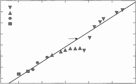
Theresearchphaseoffiber-opticcommunicationsystemsstartedaround1975.Theenormous progressrealizedoverthe25-yearperiodextendingfrom1975to2000canbegroupedintoseveral distinctgenerations.Figure1.4showstheincreaseinthe BL productoverthistimeperiodas quantifiedthroughvariouslaboratoryexperiments[14].Thestraightlinecorrespondstoadoubling ofthe BL producteveryyear.Ineverygeneration, BL increasesfirstexponentiallybutreachesa
Figure1.3: Increaseinthecapacityoflightwavesystemsrealizedafter1980.Thelinesindicateanearlyexponentialgrowthinthebitrateforboththeresearchandcommercialsystems.Notethechangeintheslope aroundtheyear2001.
Figure1.4: Increaseinthe BL productovertheperiod1975to2000throughseveralgenerationsoflightwave systems.Differentsymbolsareusedforsuccessivegenerations.Source:Kogelnik[14],p.1282/IEEE.
saturationlevelasthetechnologymatures.Eachnewgenerationbringsafundamentalchangethat helpstoimprovethe BL productfurther.
ThefirstgenerationoflightwavesystemsemployedGaAssemiconductorlasersandoperated near0.85 �� m.Afterseveralfieldtrialsduringtheperiod1977–79,suchsystemsbecameavailable commerciallyin1980[15].Theyoperatedatabitrateof45Mb/sandallowedrepeaterspacingsof upto10km.Thelargerrepeaterspacingcomparedwith1-kmspacingofcoaxialsystemswasan importantmotivationforsystemdesignersbecauseitdecreasedtheinstallationandmaintenance costsassociatedwitheachrepeater.
Itwasrealizedafter1975thattherepeaterspacingcouldbeincreasedconsiderablybyoperating thelightwavesysteminthewavelengthregionnear1.3 �� m,wherefiber’slosswasbelow1dB/km.
Furthermore,silicafibersexhibitminimumdispersioninthiswavelengthregion.Thisrealizationled toaworldwideeffortforthedevelopmentofInGaAsPsemiconductorlasersanddetectorsoperatingnear1.3 �� m.Thesecondgenerationoffiber-opticcommunicationsystemsbecameavailablein theearly1980s,butthebitrateofearlysystemswasinitiallylimitedtobelow100Mb/sbecause oftheuseofmultimodefibers[16].Thislimitationwasovercomebydeveloping single-mode fibers. Alaboratoryexperimentin1981demonstratedtransmissionat2Gb/sover44kmofsingle-mode fiber[17].Theintroductionofcommercialsystemssoonfollowed.By1987,second-generationlightwavesystemswerecommerciallyavailable;theyoperatedatbitratesofupto1.7Gb/switharepeater spacingofabout50km.
Therepeaterspacingofsecond-generationsystemswasalsolimitedbythefiberloss(about 0.5dB/km)attheiroperatingwavelengthsnear1.3 �� m.Lossesofsilicafibersbecomeminimum closeto1.55 �� m,takingavalueofabout0.2-dB/kminthisspectralregion[18].However,the introductionofthird-generationlightwavesystemsoperatingat1.55 �� mwasconsiderablydelayed becauseofarelativelylargedispersionoffibersinthisregion.ConventionalInGaAsPlasers couldnotbeusedbecauseoftheirwidespectrum,resultingfromthesimultaneouspresence ofseverallongitudinalmodes.Thedispersionproblemwassolvedbyusingdispersion-shifted fibersdesignedtohaveminimumdispersionnear1.55 �� m,orbylimitingthelaserspectrumtoa singlelongitudinalmode.Bothapproacheswerefollowedduringthe1980s.By1985,laboratory experimentsindicatedthepossibilityoftransmittinginformationatbitratesofupto4Gb/s overdistancesinexcessof100km[19].Third-generationlightwavesystemsoperatingat2.5Gb/s becameavailablecommerciallyin1990.Suchsystemsarecapableofoperatingatabitrateofupto 10Gb/s[20].Thebestperformanceisachievedusingdispersion-shiftedfibersincombinationwith lasersoscillatinginasinglelongitudinalmode.
Adrawbackofthethird-generation1.55-�� msystemswasthattheopticalsignalrequiredperiodic regenerationthroughelectronicrepeatersspacedapartby60–80km.Therepeaterspacingcould beincreasedbymakinguseofaheterodynedetectionschemethatrequiredlesspoweratthe receiver.Suchsystemswerereferredtoascoherentlightwavesystemsandwereunderdevelopment duringthe1980s,andtheirpotentialbenefitsweredemonstratedinmanysystemexperiments[21]. However,commercialintroductionofsuchsystemswaspostponedwiththeadventoffiber amplifiersin1989.
Thefourthgenerationoflightwavesystemsmadeuseof opticalamplification forincreasingthe repeaterspacingandof wavelength-divisionmultiplexing (WDM)forincreasingthebitrate.As seenfromFigures1.3and1.4,theadventoftheWDMtechniquearound1992startedarevolutionthatresultedindoublingofthesystemcapacityevery6monthsorsoandledby2001to lightwavesystemsoperatingatabitrateof10Tb/s.InmostWDMsystems,fiberlossesarecompensatedperiodicallyusingerbium-dopedfiberamplifiersspaced60–80kmapart.Suchamplifiers weredevelopedafter1985andbecameavailablecommerciallyby1990.A1991experimentshowed thepossibilityofdatatransmissionover21,000kmat2.5Gb/s(andover14,300kmat5Gb/s) usingarecirculating-loopconfiguration[22].Thisperformanceindicatedthatanamplifier-based, all-optical,submarinetransmissionsystemwasfeasibleforintercontinentalcommunication.By 1996,transmissionover11,300kmatabitrateof5Gb/shadbeendemonstratedbyusingactual submarinecables[23].Soonafter,commercialtransatlanticandtranspacificcablesbecameavailable. Sincethen,alargenumberofsubmarinelightwavesystemshavebeendeployedworldwide.
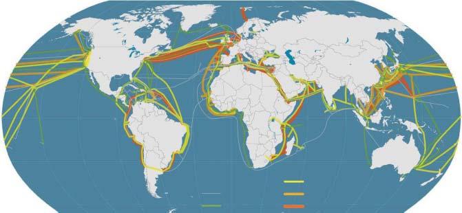
Figure1.5showstheinternationalnetworkofsubmarinecablesoperatingin2016.The 27,000-km-longfiber-opticlinkaroundtheglobe(knownasFLAG)becameoperationalin1998, linkingmanyAsianandEuropeancountries[24].Anothermajorlightwavesystem,knownas AfricaOne,wasoperatingby2000;itcirclestheAfricancontinentandcoversatotaltransmission distanceofabout35,000km[25].SeveralWDMsystemsweredeployedacrosstheAtlanticand Pacificoceansduring1998–2001inresponsetotheInternet-inducedincreaseinthedatatraffic; theyincreasedthetotalcapacitybyordersofmagnitudes.Indeed,sucharapiddeploymentledto
Figure1.5: Internationalunderseanetworkoffiber-opticcommunicationsystemsaround2016.
Source:Agrawal[3]/SpringerNature/PublicDomianCCBY-4.0.
aworldwideovercapacitythatresultedintheburstingoftheso-called“telecombubble”in2001. ThechangeintheslopesofthetwolinesinFigure1.3,occurringaround2001,reflectsthisreality.
After2001,theemphasisofmostWDMsystemswasonincreasingtheircapacitybytransmittingmoreandmorechannelsoverthesamefiber.Asthesignal’sbandwidthincreased,itwas oftennotpossibletoamplifyallchannelsusingasingleamplifier.Asaresult,newamplification schemes(suchasdistributedRamanamplification)weredevelopedforcoveringthespectralregion extendingfrom1.45to1.62 �� m.Thisapproachledin2000toa3.28-Tb/sexperimentinwhich 82channels,eachoperatingat40Gb/s,weretransmittedover3000km.Withinayear,thesystem capacitycouldbeincreasedtobeyond10Tb/s(273WDMchannels,eachoperatingat40Gb/s)but thetransmissiondistancewaslimitedto117km[26].Inanotherexperiment,300channels,each operatingat11.6Gb/s,weretransmittedover7380km,resultingina BL productofmorethan 25,000(Tb/s)-km[27].Commercialterrestrialsystemswiththecapacityof3.2Tb/s,transmitting80 channels(eachat40Gb/s)withtheuseofRamanamplification,wereavailablebytheendof2003. Giventhatthefirst-generationsystemshadacapacityofonly45Mb/sin1980,thecapacityof fourth-generationsystemshadincreasedbyafactorofmorethan70,000overaperiodof25years.
Thefifthgenerationbasedoncoherentcommunicationtechnologybeganaround2005withits focusonincreasingthespectralefficiencyofWDMsystems.Theideawastoemployadvanced modulationformatsinwhichinformationwasencodedusingboththeamplitudeandphaseofthe opticalcarrier[28].Althoughsuchformatsweredevelopedandusedformicrowavesystemsmuch earlier,theiruseforlightwavesystemsattractedseriousattentiononlyafter2001.Ithasallowedus toincreasethespectralefficiency,limitedtobelow1bit/s/Hzforthefourth-generationsystems,to morethan10bit/s/Hz.ThewavelengthrangeoverwhichaWDMsystemcanoperatehasalsobeen extended.Theconventionalwavelengthwindow,knownastheCband,coveredthewavelength range1.53–1.57 �� m.Itwasextendedonboththelong-andshort-wavelengthsides,resultingin theLandSbands,respectively.Anewkindoffiber,knownasthe dryfiber,hasbeendeveloped withthepropertythatfiberlossesaretolerableoverthewavelengthregionextendingfrom1.25to 1.65 �� m[29].Ina2010experiment[30],anewrecordwasestablishedwhen64-Tb/stransmission wasrealizedover320kmusing640WDMchannelsthatspannedboththeCandLbandswith 12.5-GHzchannelspacing.Eachchannelcontainedtwopolarization-multiplexed107-Gb/ssignals codedwithamodulationformatknownasquadratureamplitudemodulation.
Thefocusofthesixthgenerationoflightwavesystemsisonincreasingtheircapacitythrougha multiplexingtechniqueknownasspace-divisionmultiplexing(SDM).Onecanclaim,withsome justification,thatSDMwasusedearlierinunderseasystems,whosecablesemployedmultiplefiber
pairsforenhancingthesystem’scapacity.Inthemoderncontext,SDMmakesuseofopticalfibers containingmultiplecores,orasinglewidecoresupportingmultiplemodes.Whenmultimodefibers areemployed,SDMisalsoreferredtoasmode-divisionmultiplexing.A19-corefiberwasused ina2013experimenttoincreaseasystem’scapacityto305Tb/s[31].By2015,thetotalcapacity ofmulticoresystemsexceeded1000Tb/s[32].Moreover,thedataatsuchhighspeedscouldbe transmittedoverdistancesexceeding1000km.
Eventhoughthefiber-opticcommunicationtechnologyisbarely40yearsold,ithasprogressed rapidlyandhasreachedacertainstageofmaturity.Thisisalsoapparentfromseveralbooksand reviewarticlesonopticalcommunicationsthatprovideanindicationofhowtheunderlyingtechnologyhasevolvedduringthisperiod[33–40].Thefiftheditionofthisbook(firsteditionpublished in1992)isintendedtopresentanup-to-dateaccountoffiber-opticcommunicationssystemswith emphasisonrecentdevelopments.
1.2BasicConcepts
Thissectionintroducesafewbasicconcepts,commontoallcommunicationsystems.Itbeginswith adescriptionoftheanaloganddigitalsignalsanddescribeshowananalogsignalcanbeconverted intoadigitalform.Wethenfocusonmultiplexingofinputsignalsinthetimeandfrequencydomains anddiscussvariousmodulationformats.
1.2.1AnalogandDigitalSignals
Inanycommunicationsystem,informationtobetransmittedisgenerallyavailableasanelectrical signalthatmaytake analog or digital form[41].Intheanalogcase,thesignal(e.g.,electriccurrent) variescontinuouslywithtime,asshownschematicallyinFigure1.6(a).Familiarexamplesinclude audioandvideosignalsresultingwhenamicrophoneconvertsvoiceoravideocameraconvertsan imageintoanelectricalsignal.Bycontrast,thedigitalsignaltakesonlyafewdiscretevalues.Inthe binaryrepresentation ofadigitalsignalonlytwovaluesarepossible.Thesimplestcaseofabinary digitalsignalisoneinwhichtheelectriccurrentiseitheronoroff,asshowninFigure1.6(b).These twopossibilitiesarecalled“bit1”and“bit0”(bit isacontractedformof binarydigit).Eachbit lastsforacertainperiodoftime TB ,knownasthebitperiodor bitslot.Sinceonebitofinformation isconveyedinatimeinterval TB ,thebitrate B,definedasthenumberofbitspersecond,issimply B = T 1 B .Awell-knownexampleofdigitalsignalsisprovidedbycomputerdata.Eachletterof thealphabettogetherwithothercommonsymbols(decimalnumerals,punctuationmarks,etc.)is assignedacodenumber(ASCIIcode)intherange0–127whosebinaryrepresentationcorresponds toa7-bitdigitalsignal.TheoriginalASCIIcodehasbeenextendedtorepresent256characters transmittedthrough8-bitbytes.Bothanaloganddigitalsignalsarecharacterizedbytheirbandwidth,whichisameasureofthespectralcontentsofthesignal.The signalbandwidth represents therangeoffrequenciescontainedwithinthesignalandisdeterminedmathematicallythroughits Fouriertransform.
Ananalogsignalcanbeconvertedintodigitalformbysamplingitatregularintervalsoftime[41]. Figure1.7showstheconversionmethodschematically.Thesamplingrateisdeterminedbythe bandwidth Δf oftheanalogsignal.Accordingtothesamplingtheorem[42],abandwidth-limited signalcanbefullyrepresentedbydiscretesamples,withoutanylossofinformation,providedthat thesamplingfrequency fs satisfiesthe Nyquistcriterion [43], fs ≥ 2Δf .Thefirststepconsistsof samplingtheanalogsignalattherightfrequency.Thesampledvaluescantakeanyvalueintherange 0 ≤ A ≤ Amax ,where Amax isthemaximumamplitudeofthegivenanalogsignal.Letusassumethat Amax isdividedinto M discrete(notnecessarilyequallyspaced)intervals.Eachsampledvalueis
Figure1.6: Representationof(a)ananalogsignaland(b)adigitalsignal.
quantizedtocorrespondtooneofthesediscretevalues.Clearly,thisprocedureleadstoadditional noise,knownas quantizationnoise,whichaddstothenoisealreadypresentintheanalogsignal.
Theeffectofquantizationnoisecanbeminimizedbychoosingthenumberofdiscretelevelssuch that M > Amax ∕AN ,where AN istheroot-mean-squarenoiseamplitudeoftheanalogsignal.The ratio Amax ∕AN iscalledthedynamicrangeandisrelatedtothe signal-to-noiseratio (SNR)bythe relation
SNR = 20log10 (Amax ∕AN ), (1.2.1) whereSNRisexpressedindecibel(dB)units.Anyratio R canbeconvertedintodecibelsbyusing thegeneraldefinition10log10 R (seeAppendixA).Equation(1.2.1)containsafactorof20inplace of10simplybecausetheSNRforelectricalsignalsisdefinedwithrespecttotheelectricalpower, whereas A isrelatedtotheelectriccurrent(orvoltage).
Thequantizedsampledvaluescanbeconvertedintodigitalformatbyusingasuitableconversion technique.Inonescheme,knownas pulse-positionmodulation,pulsepositionwithinthebitslotis ameasureofthesampledvalue.Inanother,knownas pulse-durationmodulation,thepulsewidth isvariedfrombittobitinaccordancewiththesampledvalue.Thesetechniquesarerarelyusedin practicalopticalcommunicationsystems,sinceitisdifficulttomaintainthepulsepositionorpulse widthtohighaccuracyduringpropagationinsidethefiber.Thetechniqueusedalmostuniversally, knownas pulse-codemodulation (PCM),isbasedonabinaryschemeinwhichinformationisconveyedbytheabsenceorthepresenceofpulsesthatareotherwiseidentical.Abinarycodeisusedto converteachsampledvalueintoastringof1and0bits.Thenumberofbits m neededtocodeeach sampleisrelatedtothenumberofquantizedsignallevels M bytherelation
Figure1.7: Threestepsof(a)sampling,(b)quantization,and(c)codingrequiredforconvertingananalog signalintoabinarydigitalsignal.
ThebitrateassociatedwiththePCMdigitalsignalisthusgivenby
wheretheNyquistcriterion, fs ≥ 2Δf ,wasused.Bynotingthat M > Amax ∕AN andusingEq.(1.2.1) togetherwithlog2 10 ≈ 3.33,
wheretheSNRisexpressedindecibel(dB)units.
Equation(1.2.4)providestheminimumbitraterequiredfordigitalrepresentationofananalog signalofbandwidth Δf andaspecificSNR.WhenSNR > 30dB,therequiredbitrateexceeds 10(Δf ),indicatingaconsiderableincreaseinthebandwidthrequirementsofdigitalsignals.Despite thisincrease,thedigitalformatisalmostalwaysusedforopticalcommunicationsystems.This choiceismadebecauseofthesuperiorperformanceofdigitaltransmissionsystems.Lightwavesystemsoffersuchanenormousincreaseinthesystemcapacity(byafactor ∼ 105 )comparedwith microwavesystemsthatsomebandwidthcanbetradedforimprovedperformance.
AsanillustrationofEq.(1.2.4),considerthedigitalconversionofanaudiosignalgeneratedina telephone.Theanalogaudiosignalcontainsfrequenciesintherange0.3–3.4kHzwithabandwidth
Δf = 3.1kHzandhasaSNRofabout30dB.Equation(1.2.4)indicatesthat B > 31kb/s.Inpractice, adigitalaudiochanneloperatesat64kb/s.Theanalogsignalissampledatintervalsof125 �� s (samplingrate fs = 8kHz),andeachsampleisrepresentedby8bits.Therequiredbitratefora digitalvideosignalishigherbymorethanafactorof1000.Theanalogtelevisionsignalhasa bandwidth ∼4MHzwithaSNRofabout50dB.TheminimumbitratefromEq.(1.2.4)is66Mb/s. Inpractice,adigitalvideosignalrequiresabitrateof100Mb/sormoreunlessitiscompressedby usingastandardformat(suchasMPEG-4).
1.2.2ChannelMultiplexing
Asseenintheprecedingdiscussion,adigitalvoicechanneloperatesat64kb/s.Mostfiber-optic communicationsystemsarecapableoftransmittingatarateofmorethan1Gb/s.Toutilizethesystemcapacityfully,itisnecessarytotransmitmanychannelssimultaneouslythroughmultiplexing. Thiscanbeaccomplishedthrough time-division multiplexing(TDM)or frequency-division multiplexing(FDM).InthecaseofTDM,bitsassociatedwithdifferentchannelsareinterleavedinthe timedomaintoformacompositebitstream.Forexample,thebitslotisabout15 �� sforasingle voicechanneloperatingat64kb/s.FivesuchchannelscanbemultiplexedthroughTDMifthebit streamsofsuccessivechannelsaredelayedby3 �� s.Figure1.8(a)showstheresultingbitstream schematicallyatacompositebitrateof320kb/s.
Figure1.8: (a)Time-divisionmultiplexingoffivedigitalvoicechannelsoperatingat64kb/s;(b)frequencydivisionmultiplexingofthreeanalogsignals.
InthecaseofFDM,thechannelsarespacedapartinthefrequencydomain.Eachchanneliscarriedbyitsowncarrierwave.Thecarrierfrequenciesarespacedmorethanthechannelbandwidth sothatthechannelspectradonotoverlap,asseenFigure1.8(b).FDMissuitableforbothanalog anddigitalsignalsandisusedinbroadcastingofradioandtelevisionchannels.TDMisreadily implementedfordigitalsignalsandiscommonlyusedfortelecommunicationnetworks.ItisimportanttorealizethatTDMandFDMcanbeimplementedinboththeelectricalandopticaldomains; opticalFDMisoftenreferredtoasWDM.Chapter6isdevotedtooptical-domainmultiplexing techniques.ThissectioncoverselectricalTDM,whichisemployeduniversallytomultiplexalarge numberofvoicechannelsintoasingleelectricalbitstream.
TheconceptofTDMhasbeenusedtoform digitalhierarchies.InNorthAmericaandJapan,the firstlevelcorrespondstomultiplexingof24voicechannelswithacompositebitrateof1.544Mb/s (hierarchyDS-1),whereasinEurope30voicechannelsaremultiplexed,resultinginacompositebit rateof2.048Mb/s.Thebitrateofthemultiplexedsignalisslightlylargerthanthesimpleproduct of64kb/swiththenumberofchannelsbecauseofextracontrolbitsthatareaddedforseparating (demultiplexing)thechannelsatthereceiverend.Thesecond-levelhierarchyisobtainedbymultiplexing4DS-1TDMchannels.Thisresultsinabitrateof6.312Mb/s(hierarchyDS-2)forNorth AmericaorJapanand8.448Mb/sforEurope.Thisprocedureiscontinuedtoobtainhigher-level hierarchies.Forexample,atthefifthlevelofhierarchy,thebitratebecomes565Mb/sforEurope and396Mb/sforJapan.
Thelackofaninternationalstandardinthetelecommunicationindustryduringthe1980sledto theadventofanewstandard,firstcalledthe synchronousopticalnetwork (SONET)andlatertermed the synchronousdigitalhierarchy orSDH[44–46].ItdefinesasynchronousframestructurefortransmittingTDMdigitalsignals.ThebasicbuildingblockoftheSONEThasabitrateof51.84Mb/s. ThecorrespondingopticalsignalisreferredtoasOC-1,whereOCstandsforopticalcarrier.Inthe SDHstandardG.707developedbytheInternationalTelecommunicationUnion(ITU),thelevel-1 datablockhasabitrateof155.52Mb/sandisreferredtoasSTM-1,whereSTMstandsfora synchronoustransportmodule.AusefulfeatureoftheSDHisthathigherlevelshaveabitratethatisan exactmultipleofthebasicbitrate.Table1.1liststhecorrespondencebetweenSONETandSDHbit ratesforseverallevels.LightwavesystemsoperatingattheSTM-64level(B ≈ 10Gb/s)areavailable since1996[20].CommercialSTM-256(OC-768)systemsoperatingnear40Gb/sbecameavailable by2002.
WiththeadventoftheWDMtechnology,ITUintroducedin2003anewstandard(G.709)known asopticaltransporthierarchy(OTH).Itdefinesanopticaltransportunit(OTU)suchthatOTU-1 correspondstothebitrateofSTM-16,OTU-2tothatofSTM-64,andOTU-3tothatofSTM-256. Inthisscheme,thebitrateforOTU-4doesnotjumpbyafactorof4butiscloseto100Gb/s (motivatedby100GEthernet).Indeed,WDMsystemswitheachchanneloperatingat100-Gb/s weredevelopedafter2005whentheuseofcoherentdetectionbecamepractical.By2010,thebit
Table1.1SONET/SDHbitrates
rateofeachWDMchannelhasreached400Gb/s,andbitrateshigherthan1Tb/swerebeing consideredby2020.
1.2.3ModulationFormats
Thefirststepinthedesignofanopticalcommunicationsystemistodecidehowanelectrical bitstreamwouldbeconvertedintoitsopticalform.Normally,theoutputofanopticalsource, suchasasemiconductorlaser,ismodulatedbyapplyingtheelectricalsignaleitherdirectlytothe opticalsourceortoanexternalmodulator.Therearetwochoicesforthemodulationformatof theresultingopticalbitstream.TheseareshowninFigure1.9andareknownasthe return-to-zero (RZ)and nonreturn-to-zero (NRZ)formats.IntheRZformat,eachopticalpulserepresentingbit 1isshorterthanthebitslot,anditsamplitudereturnstozerobeforethebitdurationisover.In theNRZformat,theopticalpulseremainsonthroughoutthebitslotanditsamplitudedoesnot droptozerobetweentwoormoresuccessive1bits.Asaresult,pulsewidthvariesdependingon thebitpattern,whereasitremainsthesameinthecaseofRZformat.AnadvantageoftheNRZ formatisthatthebandwidthassociatedwiththebitstreamissmallerthanthatoftheRZformatby aboutafactorof2simplybecauseon–offtransitionsoccurfewertimes.However,itsuserequires tightercontrolofthepulsewidthandmayleadtobit-pattern-dependenteffectsiftheopticalpulse spreadsduringtransmission.TheNRZformatissometimesusedinpracticebecauseofasmaller signalbandwidthassociatedwithit.
TheuseoftheRZformatintheopticaldomainbegantoattractattentionaround1999afterit wasfoundthatitsusemayhelpthedesignofhigh-capacitylightwavesystems[47–49].Bynow,this formatisusedalmostexclusivelyforWDMchannelsdesignedtooperateat40Gb/sormore.An exampleoftheusefulnessoftheRZformatisprovidedbytheso-calledpseudo-linearsystems[50], whichemployrelativelyshortopticalpulsesthatspreadovermultiplebitslotsquicklyastheypropagatedownthefiberlink.Thisspreadingreducesthepeakpowerandlowerstheimpactofseveral nonlineareffectsthatmayprovedetrimentalotherwise.Pulsesareeventuallycompressedbackto
(a)
(b) RZ signal NRZ signal
Figure1.9: Digitalbitstream010110 codedbyusing(a)return-to-zero(RZ)and(b)nonreturn-to-zero (NRZ)formats.
theiroriginalwidthusingadispersion-managementtechnique.Suchsystemsmayemployavariant oftheRZformat,knownasthechirpedRZ(orCRZ)format,inwhichopticalpulsesareprechirped beforetheyarelaunchedintothefiber.
Animportantissueisrelatedtothechoiceofthephysicalvariablethatismodulatedtoencode theelectricaldataonanopticalcarrier.Theopticalcarrierwavebeforemodulationisoftheform
where E istheelectricfieldvector, ̂ e isthepolarizationunitvector, a istheamplitude, ��0 isthe carrierfrequency,and �� isthephase.Thespatialdependenceof E issuppressedforsimplicityof notation.Onemaychoosetomodulatetheamplitude a,thefrequency ��0 ,orthephase ��.Inthe caseofanalogmodulation,thethreemodulationchoicesareknownasamplitudemodulation(AM), frequencymodulation(FM),andphasemodulation(PM).AsshownschematicallyinFigure1.10, thesamemodulationtechniquescanbeappliedinthedigitalcaseandarecalledamplitude-shift keying(ASK),frequency-shiftkeying(FSK),andphase-shiftkeying(PSK),dependingonwhether theamplitude,frequency,orphaseofthecarrierwaveisshiftedbetweenthetwolevelsofabinary digitalsignal.Thesimplesttechniqueconsistsofsimplychangingthesignalpowerbetweentwo levels,oneofwhichissettozero,andisoftencalled on–offkeying (OOK)toreflecttheon–off natureoftheresultingopticalsignal.Untilrecently,OOKwastheformatofchoiceformostdigital lightwavesystems.
AlthoughtheuseofFSKandPSKformatswasexploredduringthe1980sinthecontextof coherentdetection[21],theseformatswereabandonedduringthe1990becausetheadventofoptical amplifiersandtheWDMtechnologysolvedmostissuesrelevantatthattime.Thesituationchanged after2000whenitwasrealizedthattheuseofaPSKformatwasessentialforimprovingthespectral efficiencyofWDMsystems.By2010,mostWDMsystemsemployedmodulationformatsthatcoded
Figure1.10: (a)Anelectricalbitstreamandtheresultingelectricfieldpatternswhenitisconvertedtooptical domainusing(b)ASK,(c)FSK,(d)PSKmodulationformats.
Figure1.11: Constellationdiagramsfor(a)ASK,(b)PSK,(c)QPSK,and(d)multilevelQPSKformats.
informationusingboththeamplitudeandphaseofanopticalcarrier[36].Thebasicideabehindthe newformatscanbeunderstoodbyemployingthecomplexnotationfortheelectricfieldinEq.(1.2.5) andintroducingtheso-calledphasoras A = aei�� .Figure1.11showsfourmodulationformatsinthe constellationdiagrams,wheretherealandimaginarypartsof A areplottedalongthe x and y axes, respectively.ThefirsttwoconfigurationsrepresentthestandardbinaryASKandPSKformatsin whicheithertheamplitudeofthephaseofelectricfieldtakestwovaluesmarkedbycircles.Thethird oneshowsthequadraturePSK(orQPSK)formatinwhichtheopticalphasetakesfourpossible values.Thisformat,discussedfurtherinChapter10,transmitstwobitsduringeachsymbolslot, andtheeffectivebitrateishalved.Borrowingfromthemicrowavecommunicationterminology[41], theeffectivebitrateiscalledthe symbolrate (orbaud).ThelastexampleinFigure1.11showshow thesymbolconceptcanbeextendedtomultilevelsignalingsuchthateachsymbolcarries4bits ormore.Anadditionalfactoroftwocanbegainedifonetransmitstwoorthogonallypolarized symbolssimultaneouslyduringeachsymbolslot.
1.3OpticalCommunicationSystems
Asmentionedearlier,opticalcommunicationsystemsdifferinprinciplefrommicrowavesystems onlyinthefrequencyrangeofthecarrierwaveusedtocarrytheinformation.Theopticalcarrier frequenciesaretypically ∼200THz,incontrastwiththemicrowavecarrierfrequencies(∼1GHz). Anincreaseintheinformationcapacityofopticalcommunicationsystemsbyafactorofupto 10,000isexpectedsimplybecauseofsuchhighcarrierfrequenciesusedforlightwavesystems.This increasecanbeunderstoodbynotingthatthebandwidthofthemodulatedcarriercanbeupto afewpercentofthecarrierfrequency.Taking,forillustration,1%asthelimitingvalue,optical communicationsystemshavethepotentialofcarryinginformationatbitrates ∼1Tb/s.Itisthis enormouspotentialbandwidthofopticalcommunicationsystemsthatisthedrivingforcebehind theworldwidedevelopmentanddeploymentoflightwavesystems.Currentstate-of-the-artsystems operateatbitrates ∼10Gb/s,indicatingthatthereisconsiderableroomforimprovement.
Figure1.12showsagenericblockdiagramofanopticalcommunicationsystem.Itconsistsofa transmitter,acommunicationchannel,andareceiver,thethreeelementscommontoallcommunicationsystems.Opticalcommunicationsystemscanbeclassifiedintotwobroadcategories: guided and unguided.Asthenameimplies,inthecaseofguidedlightwavesystems,theopticalbeamemitted
bythetransmitterremainsspatiallyconfined.Thisisrealizedinpracticebyusingopticalfibers,as discussedinChapter2.Sinceallguidedopticalcommunicationsystemscurrentlyuseopticalfibers, thecommonlyusedtermforthemisfiber-opticcommunicationsystems.Theterm lightwavesystem isalsousedforfiber-opticcommunicationsystems,althoughitshouldgenerallyincludeboth guidedandunguidedsystems.
Inthecaseofunguidedopticalcommunicationsystems,theopticalbeamemittedbythetransmitterspreadsinspace,similartothespreadingofmicrowaves.However,unguidedopticalsystems arelesssuitableforbroadcastingapplicationsthanmicrowavesystemsbecauseopticalbeamsspread mainlyintheforwarddirection(asaresultoftheirshortwavelength).Theirusegenerallyrequires accuratepointingbetweenthetransmitterandthereceiver.Inthecaseofterrestrialpropagation, thesignalinunguidedsystemscandeteriorateconsiderablybyscatteringwithintheatmosphere. Thisproblem,ofcourse,disappearsin free-spacecommunications abovetheearthatmosphere(e.g., intersatellitecommunications).Althoughfree-spaceopticalcommunicationsystemsareneededfor certainapplicationsandhavebeendevelopedextensively[51],mostterrestrialapplicationsmakeuse of fiber-opticcommunicationsystems.Thisbookdoesnotconsiderunguidedopticalcommunication systems.
Theapplicationoffiber-optictransmissionispossibleinanyareathatrequirestransferofinformationfromoneplacetoanother.However,fiber-opticcommunicationsystemshavebeendevelopedmostlyfortelecommunicationsapplications.Thisisunderstandableinviewoftheworldwide telephonenetworksusedtotransmitnotonlyvoicesignalsbutalsocomputerdataandfaxmessages.Thetelecommunicationapplicationscanbebroadlyclassifiedintotwocategories, long-haul and short-haul,dependingonwhethertheopticalsignalistransmittedoverrelativelylongorshort distancescomparedwithtypicalintercitydistances(∼100km).Long-haultelecommunicationsystemsrequirehigh-capacitytrunklinesandbenefitmostbytheuseoffiber-opticlightwavesystems. Indeed,thetechnologybehindopticalfibercommunicationisoftendrivenbylong-haulapplications.Eachsuccessivegenerationoflightwavesystemsiscapableofoperatingathigherbitratesand overlongerdistances.Periodicregenerationoftheopticalsignalbyusingrepeatersisstillrequired formostlong-haulsystems.However,considerableincreaseinboththerepeaterspacingandthebit rate,comparedwiththoseofcoaxialsystems,hasmadetheuseoflightwavesystemsveryattractive forlong-haulapplications.Furthermore,theuseofWDMwithopticalamplifiershasreducedthe overallcostwhileincreasingsystemcapacity.AsseeninFigure1.5,alargenumberoftransoceanic lightwavesystemshavealreadybeeninstalledtocreateaninternationalfiber-opticnetwork.
Short-haultelecommunicationapplicationscoverintracityandlocal-looptraffic.Suchsystems typicallyoperateatlowbitratesoverdistancesoflessthan50km.Theuseofsingle-channellightwavesystemsforsuchapplicationsisnotverycosteffective.Forthisreason,theuseofWDMhas becomerelevantevenforshort-haulsystems.WiththeadventoftheInternetinthe1990s,datatrafficinvolvingtransmissionofvideoandstillimageshasbecomemuchmorecommonandbynow suchtrafficconsumesmorebandwidththanthetraditionaltelephonetraffic.TheuseofInternet protocolinvolvingpacketswitchingisincreasingcontinuously.Onlymodernfiber-opticWDMsystemscanmeettherapidlygrowingbandwidthrequirements.Multichannellightwavesystemsand theirapplicationsarediscussedinChapter6.
1.4LightwaveSystemComponents
ThegenericblockdiagramofFigure1.12appliestoafiber-opticcommunicationsystem,theonly differencebeingthatthecommunicationchannelisanopticalfibercable.Theothertwocomponents,theopticaltransmitterandtheopticalreceiver,aredesignedtomeettheneedsofsucha specificcommunicationchannel.Inthissection,wediscussthegeneralissuesrelatedtotherole
ofopticalfiberasacommunicationchannelandtothedesignoftransmittersandreceivers.The objectiveistoprovideanintroductoryoverview,asthethreecomponentsarediscussedindetailin Chapters2–4.
1.4.1OpticalFibersasaCommunicationChannel
Theroleofacommunicationchannelistotransporttheopticalsignalfromtransmittertoreceiver withoutdistortingit.Mostlightwavesystemsuseopticalfibersasthecommunicationchannel becausesilicafiberscantransmitlightwithlossesassmallas0.2dB/km.Eventhen,opticalpower reducestoonly1%after100km.Forthisreason,fiberlossesremainanimportantdesignissue anddeterminestherepeateroramplifierspacingofalong-haullightwavesystem.Anotherimportantdesignissueis fiberdispersion,whichleadstobroadeningofindividualopticalpulseswith propagation.Ifopticalpulsesspreadsignificantlyoutsidetheirallocatedbitslot,thetransmitted signalisseverelydegraded.Eventually,itbecomesimpossibletorecovertheoriginalsignalwithhigh accuracy.Theproblemismostsevereinthecaseofmultimodefibers,sincepulsesspreadrapidly (typicallyatarateof ∼10ns/km)becauseofdifferentspeedsassociatedwithdifferentfibermodes. Itisforthisreasonthatmostopticalcommunicationsystemsusesingle-modefibers.Materialdispersion(relatedtothefrequencydependenceoftherefractiveindex)stillleadstopulsebroadening (typically <0.1ns/km),butitissmallenoughtobeacceptableformostapplicationsandcanbe reducedfurtherbycontrollingthespectralwidthoftheopticalsource.Nevertheless,asdiscussedin Chapter2,materialdispersionsetstheultimatelimitonthebitrateandthetransmissiondistance offiber-opticcommunicationsystems.
1.4.2OpticalTransmitters
Theroleofan opticaltransmitter istoconverttheelectricalsignalintoopticalformandtolaunch theresultingopticalsignalintotheopticalfiber.Figure1.13showstheblockdiagramofanoptical transmitter.Itconsistsofanopticalsource,amodulator,andachannelcoupler.Semiconductor lasersorlight-emittingdiodesareusedasopticalsourcesbecauseoftheircompatibilitywiththe optical-fibercommunicationchannel;botharediscussedindetailinChapter3.Theopticalsignal isgeneratedbymodulatingtheopticalcarrierwave.Althoughanexternalmodulatorissometimes used,itcanbedispensedwithinsomecases,sincetheoutputofasemiconductoropticalsource canbemodulateddirectlybyvaryingtheinjectioncurrent.Suchaschemesimplifiesthetransmitter designandisgenerallycosteffective.Thecoupleristypicallyamicrolensthatfocusestheoptical signalontotheentranceplaneofanopticalfiberwiththemaximumpossibleefficiency.
The launchedpower isanimportantdesignparameter.Onecanincreasetheamplifier(orrepeater) spacingbyincreasingit,buttheonsetofvarious nonlineareffects limitshowmuchtheinputpower