Visit to download the full and correct content document: https://ebookmass.com/product/pump-wisdom-essential-centrifugal-pump-knowledgefor-operators-and-specialists-2nd-edition-robert-x-perez/
More products digital (pdf, epub, mobi) instant download maybe you interests ...
Transcritical CO2 Heat Pump Xin-Rong Zhang
https://ebookmass.com/product/transcritical-co2-heat-pump-xinrong-zhang/
Working Guide to Pump and Pumping Stations: Calculations Simulations 1st Edition
https://ebookmass.com/product/working-guide-to-pump-and-pumpingstations-calculations-simulations-1st-edition/
Fire Pump Arrangements at Industrial Facilities 3rd ed Edition Nolan
https://ebookmass.com/product/fire-pump-arrangements-atindustrial-facilities-3rd-ed-edition-nolan/ eTextbook 978-0071457842 HVAC Pump Handbook, Second Edition (McGraw-Hill Handbooks)
https://ebookmass.com/product/etextbook-978-0071457842-hvac-pumphandbook-second-edition-mcgraw-hill-handbooks/
978-1118961940 Geothermal Heat Pump and Heat Engine Systems: Theory And Practice (Wiley-ASME Press Series)
https://ebookmass.com/product/978-1118961940-geothermal-heatpump-and-heat-engine-systems-theory-and-practice-wiley-asmepress-series/
Centrifugal Separations in Biotechnology 2nd Edition
Wallace Woon Fong Leung
https://ebookmass.com/product/centrifugal-separations-inbiotechnology-2nd-edition-wallace-woon-fong-leung/
Accounting and Finance for Non-Specialists 11th edition
Peter Atrill
https://ebookmass.com/product/accounting-and-finance-for-nonspecialists-11th-edition-peter-atrill/
A Hidden Wisdom: Medieval Contemplatives on SelfKnowledge, Reason, Love, Persons, and Immortality
Christina
Van Dyke
https://ebookmass.com/product/a-hidden-wisdom-medievalcontemplatives-on-self-knowledge-reason-love-persons-andimmortality-christina-van-dyke/
Ulam stability of operators Brzd■k
https://ebookmass.com/product/ulam-stability-of-operatorsbrzd%c8%a9k/
Pump Wisdom
Pump Wisdom
Essential Centrifugal Pump Knowledge for Operators and Specialists
Second Edition
Robert X. Perez
San Antonio, Texas
USA
Heinz P. Bloch
Montgomery, Texas USA
Copyright © 2022 by the American Institute of Chemical Engineers, Inc. All rights reserved.
A Joint Publication of the American Institute of Chemical Engineers and John Wiley & Sons, Inc.
Edition History
1st edition: Wiley 2011
Published by John Wiley & Sons, Inc., Hoboken, New Jersey.
Published simultaneously in Canada.
No part of this publication may be reproduced, stored in a retrieval system, or transmitted in any form or by any means, electronic, mechanical, photocopying, recording, scanning, or otherwise, except as permitted under Section 107 or 108 of the 1976 United States Copyright Act, without either the prior written permission of the Publisher, or authorization through payment of the appropriate per-copy fee to the Copyright Clearance Center, Inc., 222 Rosewood Drive, Danvers, MA 01923, (978) 750-8400, fax (978) 750-4470, or on the web at www.copyright.com. Requests to the Publisher for permission should be addressed to the Permissions Department, John Wiley & Sons, Inc., 111 River Street, Hoboken, NJ 07030, (201) 748-6011, fax (201) 748-6008, or online at http://www.wiley.com/go/permission.
Limit of Liability/Disclaimer of Warranty: While the publisher and author have used their best efforts in preparing this book, they make no representations or warranties with respect to the accuracy or completeness of the contents of this book and specifically disclaim any implied warranties of merchantability or fitness for a particular purpose. No warranty may be created or extended by sales representatives or written sales materials. The advice and strategies contained herein may not be suitable for your situation. You should consult with a professional where appropriate. Further, readers should be aware that websites listed in this work may have changed or disappeared between when this work was written and when it is read. Neither the publisher nor authors shall be liable for any loss of profit or any other commercial damages, including but not limited to special, incidental, consequential, or other damages.
For general information on our other products and services or for technical support, please contact our Customer Care Department within the United States at (800) 762-2974, outside the United States at (317) 572-3993 or fax (317) 572-4002.
Wiley also publishes its books in a variety of electronic formats. Some content that appears in print may not be available in electronic formats. For more information about Wiley products, visit our web site at www.wiley.com.
Library of Congress Cataloging-in-Publication Data
Names: Perez, Robert X., author. | Bloch, Heinz P., 1933– author.
Title: Pump wisdom : essential centrifugal pump knowledge for operators and specialists / Robert X. Perez, San Antonio, Texas, USA , Heinz P. Bloch, Montgomery, Texas USA.
Description: Second edition. | Hoboken, NJ., USA : Wiley, [2022] | Includes index.
Identifiers: LCCN 2021046316 (print) | LCCN 2021046317 (ebook) | ISBN 9781119748182 (hardback) | ISBN 9781119748199 (adobe pdf) | ISBN 9781119748236 (epub)
Subjects: LCSH: Pumping machinery.
Classification: LCC TJ900 .B6483 2022 (print) | LCC TJ900 (ebook) | DDC 621.6/9–dc23
LC record available at https://lccn.loc.gov/2021046316
LC ebook record available at https://lccn.loc.gov/2021046317
Cover Design: Wiley
Cover Images: © Matveev Aleksandr/Shutterstock; engineer story/Shutterstock; prabhjits/Getty Images; Grassetto/Getty Images
Set in 9.5/12.5pt STIXTwoText by Straive, Pondicherry, India
10 9 8 7 6 5 4 3 2 1
“Dedicated to the reliability technicians and engineers who will not rest until enhanced process pump safety and reliability become the new normal.”
Preface ix
1. Principles of Centrifugal Process Pumps 1
2. Pump Selection and Industry Standards 15
3. Foundations and Baseplates 23
4. Piping, Stationary Seals, and Gasketing 33
5. Rolling Element Bearings 51
6. Lubricant Application and Cooling Considerations 71
7. Lubricant Types and Key Properties 85
8. Bearing Housing Protection and Cost Justification 93
9. Mechanical Sealing Options for Long Life 101
10. Pump Operation 117
11. Impeller Modifications and Pump Maintenance 133
12. Lubrication Management 145
13. Pump Condition Monitoring: Pump Vibration, Rotor Balance, and Effect on Bearing Life 153 Contents
14. Drivers, Couplings, and Alignment 165
15. Fits, Dimensions, and Related Misunderstandings 175
16. Using Failure Statistics and Root Cause Analysis Findings to Guide Reliability Improvement Efforts 191
17. Repair, Replace, or Modify? 213
18. Centrifugal Pump Monitoring Strategies 231
19. Final Thoughts 249 Index 251
Preface
In the 10 years since the first edition of this book was compiled, upgrading in accordance with this text was largely practiced by a few best-in-class performers (“BiCs”). The feedback from these fluid machinery users was very gratifying and the publishers expressed interest in a second, expanded Edition. Robert Perez was asked to join the two-man writing team and the results are found in this updated Second Edition text. True to the subtitle we selected, you will find this volume to contain Essential Centrifugal Pump Knowledge for Operators and Specialists.
Next to electric motors, centrifugal pumps are the most frequent rotating machine man has built and put to use. Centrifugal pump users have access to hundreds of books and many thousands of articles dealing with pump subjects. So, one might ask, why do we need this text? We co-authors are certain that we need this text because an unacceptably large number of centrifugal process pumps fail catastrophically every year. An estimated 95% of these are repeat failures and most of them are quite costly, or dangerous, or both.
Essentials concentrate on explaining the many elusive failure causes that manifest themselves as repeat failures. We saw it as our mandate and task to clearly map out permanent remedial action. Our intent was to steer clear of the usual consultant-conceived generalities and give you tangible, factual, and well-defined information throughout.
As any close review of what has been offered in the past will uncover, many texts were written to primarily benefit one particular job function, ranging from centrifugal pump operators to pump designers. Some books contain a hidden bias, or they appeal to a very narrow spectrum of readers; others are perhaps influenced by a particular centrifugal pump manufacturer’s agenda. Give this text a chance, you will see that it is different. You will not find it in other texts. We gave it the title Pump Wisdom because wisdom is defined as applied knowledge. If you concur with this very meaningful definition you will be ready for a rather serious challenge. That challenge is to practice wisdom by acting on the unique knowledge this text conveys.
Preface x
Although both of us had written or co-authored other books and dozens of articles on centrifugal pump reliability improvement, some important material is too widely dispersed to be readily accessible. Moreover, some important material has never been published before. We again set out to assemble, rework, condense, and explain the most valuable points in a text aimed at ever wider distribution. With the addition of troubleshooting material, coverage of sensors, and centrifugal pump surveillance topics, it is now a text with, we hope, even more permanence and “staying power” than its predecessor edition. To thus satisfy the scope and intent of this book, we stayed with our original intention to keep theoretical explanations to a reasonable minimum and to limit the narrative to about 250 pages. Putting it another way, we wanted to squeeze into these 250 pages material and topics that will greatly enhance both centrifugal pump safety and reliability. All that is needed is the reader’s solid determination to pay close attention and to follow up diligently.
Please again realize that in years past, many centrifugal pump manufacturers have primarily concentrated their design and improvement focus on the hydraulic end. Indeed, over time and in the decades since 1960, much advancement has been made in the metallurgical and power efficiency-related performance of the hydraulic assembly. Meanwhile, the mechanical assembly or drive-end of centrifugal process pumps was being treated with relative indifference. In essence, there was an imbalance between the attention given to pump hydraulics and pump mechanical issues.
Recognizing indifference as costly, this text will indeed rectify some of these imbalances. Our narrative and illustrations are intended to do justice to both the hydraulic assembly and the mechanical assembly of centrifugal process pumps. That said, the book briefly lays out how centrifugal pumps function and quickly moves to guidelines and details that must be considered by reliability-focused readers. A number of risky omissions or shortcuts by centrifugal pump designers, manufacturers, and users are also described.
The co-authors are indebted to AESSEAL. A worldwide manufacturer of sealing products, the company was unselfish in providing many images and special artwork without making us wait for the approval of layers of bureaucracy which, in a number of other instances, has delayed or even prevented the move to more reliable pump products. The company has demonstrated an exemplary respect for the environment and is often considered as an example of how a business should conduct itself for the mutual benefit of all parties.
Please take from us a strong measure of encouragement: Make good use of this book. Read it and apply it. Today, and hopefully years from now, remember to consult this material. Doing so will acquaint you and your successors with centrifugal pump failure avoidance and the more elusive aspects of preserving pumprelated assets. And so, while you undoubtedly have more problems than you
Preface xi
deserve, please keep in mind that you also deserve access to more solutions than you previously knew about or presently apply. Sound solutions are available, and they are here, right at your fingertips. Use them wisely; they will be cost-effective. The solutions you can discern from this text will have a positive effect on centrifugal pump safety performance and asset preservation. They have worked at Best-ofClass companies and cannot possibly disappoint you.
Robert X. Perez, P.E., and Heinz P. Bloch, P.E. Fall 2020
1
Principles of Centrifugal Process Pumps
Pumps, of course, are simple machines that lift, transfer, or otherwise move fluid from one place to another. They are usually configured to use the rotational (kinetic) energy from an impeller to impart motion to a fluid. The impeller is located on a shaft; together, shaft and impeller(s) make up the rotor. This rotor is surrounded by a casing; located in this casing (or pump case) are one or more stationary passageways that direct the fluid to a discharge nozzle. Impeller and casing are the main components of the hydraulic assembly; the region or envelope containing bearings and seals is called the mechanical assembly or power end (Figure 1.1).
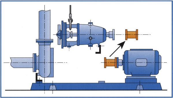
Many process pumps are designed and constructed to facilitate field repair. On these so-called “back pull-out” pumps, shop maintenance can be performed, while the casing and its associated suction and discharge piping (Figure 1.2) are left undisturbed. Although operating in the hydraulic end, the impeller remains with the power end during removal from the field.
The rotating impeller (Figure 1.3) is usually constructed with swept-back vanes, and the fluid is accelerated from the rotating impeller to the stationary passages into the surrounding casing.
In this manner, kinetic energy is added to the fluid stream (also called pumpage) as it enters the impeller’s suction eye (A on Figure 1.3), travels through the impeller, and is then flung outward toward the impeller’s periphery. After the fluid exits the impeller, it gradually decelerates to a much lower velocity in the stationary casing, called a volute casing, where the fluid stream’s kinetic energy is converted into pressure energy (also called pressure head). The combination of the pump suction (inlet) pressure and the additional pressure head generated by the impeller creates a final pump discharge pressure that is higher than the suction pressure [3].
Pump Wisdom: Essential Centrifugal Pump Knowledge for Operators and Specialists, Second Edition. Robert X. Perez and Heinz P. Bloch.
Mechanical assembly
Hydraulic assembly
Hydraulic assembly
Impeller/propeller
Suction inlet
Volute
Seal rings Shaft seal Shaft
Mechanical assembly
Labyrinth Mechanical Packing
Bearings
Housing/frame
Drive coupling/sheave
Figure 1.1 Principal components of an elementary process pump. Source: SKF USA, Inc. [1].
Pump Performance: Head and Flow
Pump performance is always described in terms of head H produced at a given flow capability Q, and hydraulic efficiency η attained at any particular intersection of H and Q. Head is customarily plotted on the vertical scale or vertical axis (the left of the two y-axes) of Figure 1.4; it is expressed in feet (or meters).
Hydraulic efficiency is often plotted on another vertical scale, the right of the two vertical scales, i.e. the y-axis in this generalized plot.
Figure 1.2 Typical process pump with suction flow entering horizontally and vertically oriented discharge pipe leaving the casing tangentially. Source: Emile Egger & Cie. [2].
Head is related to the difference between discharge pressure and suction pressure at the respective pump nozzles. Head is a simple concept, but this is where consideration of the impeller tip speed is important. The higher the shaft rpm and the larger the impeller diameter, the higher will be the impeller tip speed – actually its peripheral velocity.
Figure 1.3 A semiopen impeller with five vanes. As shown, the impeller is configured for counterclockwise rotation about a centerline “A.”
Figure 1.4 Typical “H–Q” performance curves are sloped as shown here. The best efficiency point (BEP) is marked with a small triangle; power and other parameters are often displayed on the same plot.
The concept of head can be visualized by thinking of a vertical pipe bolted to the outlet (the discharge nozzle) of a pump. In this imaginary pipe, a column of fluid would rise to a height “H”. If the vertical pipe would be attached to the discharge nozzle of a pump with higher impeller tip speed, the fluid would rise to a greater height “H+”. It is important to note that the height of a column of liquid, H or H+, is a function only of the impeller tip speed. The specific gravity of the liquid affects power demand but does not influence either H or H+. However, the resulting discharge pressure does depend on the liquid density (specific gravity or Sp.G.). For water (with an Sp.G. of 1.0), an H of 2.31 ft equals 1 psi (pound-per-squareinch), while for alcohol, which might have a Sp.G. of 0.5, a column height or head H of 4.62 ft equals 1 psi. So if a certain fluid had an Sp.G. of 1.28, a column height (head H) of 2.31/1.28 = 1.8 ft would equal a pressure of 1 psi.
For reasons of material strength and reasonably priced metallurgy, one usually limits the head per stage to about 700 ft. This is a fairly important rule-of-thumb limit to remember. When too many similar rule-of-thumb limits combine, one cannot expect pump reliability to be at its highest. As an example, say a particular impeller-to-shaft fit is to have 0.0002–0.0015 in. clearance on average size impeller hubs. With a clearance fit of 0.0015 in., one might anticipate a somewhat greater failure risk if this upper limit were found on an impeller operating with maximum allowable diameter.
On Figure 1.4, the point of zero flow (where the curve intersects the y-axis) is called the shut-off point. The point at which operating efficiency is at a peak is called the best efficiency point, or BEP. Head rise from BEP to shut-off is often chosen around 10–15% of differential head. This choice makes it easy to modulate pump flow by adjusting control valve open area based on monitoring pressure. Pumps “operate on their curves” and knowledge of what pressure relates to what flow allows technicians to program control loops.
The generalized depictions in Figure 1.4 also contain a curve labeled NPSHr, which stands for Net Positive Suction Head required. This is the head of liquid that must exist at the edge of the inlet vanes of an impeller to allow liquid transport without causing undue vaporization. It is a function of impeller geometry and size and is determined by factory testing. NPSHr can range from a few feet to a three-digit number. At all times, the head of liquid available at the impeller inlet (NPSHa) must exceed the required NPSHr.
Operation at Zero Flow
The rate of flow through a pump is labeled Q (gpm) and is plotted on the horizontal axis (the x- scale). Note that for a given speed and for every value of head H we read off on the y-axis, there is a corresponding value of Q on the x-axis. This plotted relationship is expressed as “the pump is running on its curve.” Pump H–Q curves are plotted to commence at zero flow and highest head. Process pumps need a continually rising curve inclination and a curve with a hump somewhere along its inclined line will not serve the reliability-focused user. Operation at zero flow is not allowed and, if over perhaps a minute’s duration, could cause temperature rise and internal recirculation effects that might destroy most pumps.
But remember that this curve is valid only for this particular impeller pattern, geometry, size, and operation at the speed indicated by the manufacturer or entity that produced the curve. Curve steepness or inclination has to do with the number of vanes in that impeller; curve steepness is also affected by the angle each vane makes relative to the impeller hub. In general, curve shape is verified by physical testing at the manufacturer’s facility. Once the entire pump is installed in the field, it can be re-tested periodically by the owner–purchaser for degradation and wear progression. Power draw may have been affected by seals and couplings that differ from the ones used on the manufacturer’s test stand. Occasionally, high efficiencies are alluded to in a manufacturer’s literature when bearing, seal, and coupling losses are not included in the vendor’s test reports.
Impellers and Rotors
Regardless of flow classification centrifugal pumps range in size from tiny pumps to very big pumps. The tiny ones might be used in medical or laboratory applications; the extremely large pumps may move many thousands of liters or even gallons per second from flooded lowlands to the open sea.
All six of the impellers in Figure 1.5 are shown with a hub fastening the impeller to the shaft, and each of the first five impellers is shown as a hub-and-disc version with an impeller cover. The cover (or “shroud”) identifies the first five as “closed” impellers; recall that Figure 1.3 had depicted a semiopen impeller. Semiopen impellers are designed and fabricated without the cover. Finally, open impellers come with free-standing vanes welded to or integrally cast into the hub. Since the latter incorporate neither disc nor cover, they are often used in viscous or fibrous paper stock applications.
To properly function, a semiopen impeller must operate in close proximity to a casing internal surface, which is why axial adjustment features are needed with these impellers. Axial location is a bit less critical with closed impellers. Except on axial flow pumps, fluid exits the impeller in the radial direction. Radial and mixed flow pumps are either single or double suction designs; both will be shown later. Once the impellers are fastened to a shaft, the resulting assembly is called a rotor. In radial and mixed flow pumps, the number of impellers following each other, typically called “stages,” can range from one to as many as will make such multistage pumps practical and economical to manufacture. Horizontal shaft pumps with up to 12 stages are not uncommon; using more than 12 stages on a horizontal shaft risks causing the rotor to resonate or vibrate at a so-called “critical speed.” Vertical shaft pumps have been designed with 48 or more stages. In vertical
Figure 1.5 General flow classifications of process pump impellers.
pumps, shaft support bushings are relatively lightly loaded; they are spaced so as to minimize vibration risk.
The Meaning of Specific Speed
Pump impeller flow classifications and the general meaning of specific speed deserve further discussion. Moving from left to right in Figure 1.5, the various impeller geometries reflect selections that start with high differential pressure capabilities and end with progressively lower differential pressure capabilities. Differential pressure is simply discharge pressure minus suction pressure.
Specific speed calculations are a function of several impeller parameters; the mathematical expression includes exponents and is found later, in Figure 1.6.
Staying with Figure 1.5 and again moving from left to right, we can reason that larger throughputs (flows) are more likely achieved by the configurations at right, whereas larger pressure ratios (discharge pressure divided by suction pressure) are usually achieved by the impeller geometries closer to the left of the illustration.
Impellers toward the right are more efficient than those near the left, and pump designers use the parameter specific speed (Ns) to bracket pump hydraulic efficiency attainment and other expected attributes of a particular impeller configurations and size. Please be sure not to confuse a very similar sounding parameter, pump suction specific speed (Nss or Nsss), with the specific speed (Ns). For now, we are strictly addressing specific speed (Ns).
As an example, observe the customary use, whereby with N and Q – the typical given parameters that define centrifugal process pumps – one determines a pivot point. Next, with pivot point and head H, one can easily determine Ns. In Figure 1.5, Ns is somewhere between 500 and 15 000 on the US scale. Whenever we find ourselves in that range, we know such a pump exists, and we can even observe the general impeller shape. Keep in mind that thousands of impeller combinations and geometries exist. Impellers with covers are the most prominent in hydrocarbon processes, and an uneven number of impeller vanes is favored over even numbers of vanes for reasons of vibration suppression.
Pump specific speed, Figure 1.6, might be of primary interest to pump designers, but average users will also find it useful. On the lower right, the illustration gives the equation for Ns; it will be easy to see how Ns is related to the shaft speed N (rpm), flow Q (gpm or gallons/minute), and head H (expressed in feet). This mathematical expression also has two strange-looking exponents in it, but the Ns nomogram conveys more than meets the eye and can be quite helpful.
If now, we had the same or some other Q and would want to see what happens at some other speed, we would again draw a straight line to establish the pivot point. Drawing a line from whatever H is specified through the pivot
Figure 1.6 Pump specific speed nomogram allowing quick estimations. Shown in this illustration is a hypothetical pump application with a flow of 100 gpm operating at 3600 rpm (line 1). To develop 150 ft of head with a single stage, an impeller with a specific speed of 850 (line 2) would be required.
point and to Ns we would not like to select pumps with an Ns outside the ruleof-thumb range from 500 to 15 000. In another example, we might, after establishing the pivot point, wish to determine what happens if we select an impeller with the maximum head capability of 700 ft and draw a line through the pivot point. If the resulting Ns is too low, we would try a higher speed N and see what happens.
While there are always fringe applications in terms of size and flow rate, this book deals with centrifugal pumps in process plants. These pumps are related to the generic illustrations of Figures 1.1 and 1.2 and others in this chapter. All would somewhat typically – but by no means exclusively – range from 3 to perhaps 300 hp (2–225 kW).
Process Pump Types
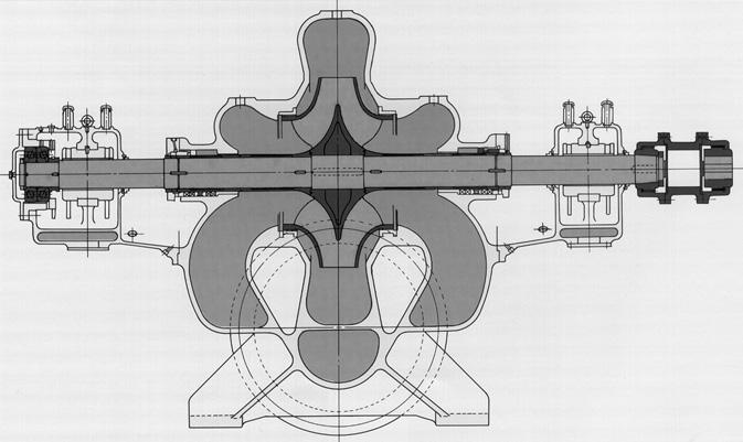
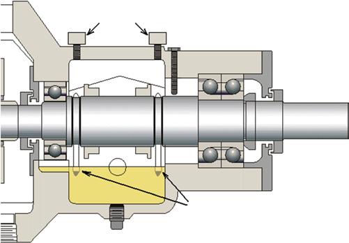
The elementary process pumps illustrated in Figures 1.1 and 1.2 probably incorporate one of the radial vane impellers shown in Figure 1.5. If a certain differential pressure is to be achieved together with higher flows, such a pump is often designed with a double-flow impeller (Figure 1.7). One of the side benefits of double-flow impellers is very good axial thrust equalization (axial balance). A small thrust bearing will often suffice; it is shown here in the left bearing housing.
Figure 1.7 Double-flow impellers are used for higher flows and relatively equalized (balanced) axial thrust. Source: Mitsubishi Heavy Industries, Ltd. [4].
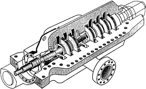
Note that the two radial bearings are plain, or sleeve-type. Certain sleeve bearings have relatively high speed capability. If elevated pressures are needed, several impellers are lined up in series on the same pump rotor. Of course, this would then turn the pump into a multistage model Figure 1.8.
Process Pump Mechanical Response to Flow Changes
After the pumped fluid (also labeled pumpage, or flow) leaves at the impeller tip, it must be channeled into a stationary passageway that merges into the discharge nozzle. Many different types of passageway designs (single or multiple volutes, vaned diffusers, etc.) are available. Their respective geometry interacts with the flow and creates radial force action of different magnitude around the periphery of an impeller (Figure 1.9). These forces tend to deflect the pump shaft; they are greater at part-flow than at full flow.
Recirculation and Cavitation
Recirculation is a flow reversal near either the inlet or discharge of a centrifugal pump. This flow reversal produces cavitation-erosion damage that starts on the high-pressure side of an impeller vane and proceeds through the metal to the lowpressure side [5].
Pump-internal recirculation can cause surging and cavitation even when the available net positive suction head (NPSHa) exceeds the manufacture’s published
Figure 1.8 A multistage centrifugal process pump.
Figure 1.9 Direction and magnitude of fluid forces change at different flows.
Source: World Pumps, February 2010, pp. 19.
NPSH required (NPSHr) by considerable margins. Also, extensive damage to the pressure side of impeller vanes has been observed in pumps operating at reduced flow rates. These are the obvious results of recirculation; however, more subtle symptoms and operational difficulties have been identified in pumps operating in the recirculation zone.
Symptoms of discharge recirculation are the following:
● Cavitation damage to the pressure side of the vane at the discharge
● Axial movement of the shaft, sometimes accompanied by damage to the thrust bearing
● Cracking or failure of the impeller shrouds at the discharge
● Shaft failure on the outboard end of double-suction and multistage pumps
● Cavitation damage to the casing tongue (see Chapter 11) or diffuser vanes
Symptoms of suction recirculation are the following:
● Cavitation damage to the pressure side of the vanes at the inlet
● Cavitation damage to the stationary vanes in the suction
● Random crackling noise in the suction; this contrasts with the steady crackling noise caused by inadequate net positive suction head
● Surging of the suction flow
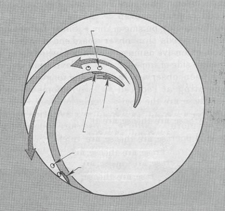
A quick-reference illustration was provided by Warren Fraser Figure 1.10. We should note that recirculation and the attendant failure risks are low in pumps delivering 2500 gpm or less at heads up to 150 ft. In those pumps, energy levels may not be high enough even if the pump operates in the recirculation zone. As a general rule for such pumps, minimum flow can be set at 50% of recirculation
Suction recirculation
Cavitation damage from low net positive suction head
Suction recirculation cavitation damage
Discharge recirculation
Discharge recirculation cavitation damage
Figure 1.10 Where and why impeller vanes get damaged. Source: Fraser [5].
flow for continuous operation and 25% of recirculation flow for intermittent operation [6].
The Importance of Suction Specific Speed
Note that pump suction specific speed (Nss or Nsss) differs from the pump specific speed Ns discussed earlier. For installations delivering over 2500 gpm and with suction specific speeds over 9000, greater care is needed. Suction specific speed (Nsss or Nss) is calculated by the straightforward mathematical expression: N ss r rgal eye NPSH / min / min / / / 12 34
wherein both the flow rate and NPSHr pertain to conditions published by the manufacturer. In each case, these conditions (flow in gpm) and NPSHr are observed on the maximum available impeller diameter for that particular pump. The higher the design suction specific speed, the closer the point of suction recirculation to what is commonly described as rated capacity. Similarly, the closer the discharge recirculation capacity is to rated capacity, the higher the efficiency. Pump system designers are tempted to aim for highest possible efficiency
TP umpfeamanPfrd Pnatfa mpPntrtn mpPPad 13
and suction specific speed. However, such designs might result in systems with either limited pump operating range or, if operated inside the recirculation range, disappointing reliability and frequent failures.
Although more precise calculations are available, trend curves of probable NPSHr for minimum recirculation and zero cavitation-erosion in water, Figure 1.11, are sufficiently accurate to warrant our attention [7]. The NPSHr needed for zero damage to impellers and other pump components may be many times that published in the manufacturer’s literature. The manufacturers’ NPSHr plot (lowermost curve in Figure 1.11) is based on observing a 3% drop in discharge head or pressure; at Q = 100%, we note NPSHr = 100% of the manufacturer’s claim. Unfortunately, whenever this 3% fluctuation occurs, a measure of damage may already be in progress. Assume the true NPSHr is as shown in Figure 1.11 and aim to provide an NPSHa in excess of this true NPSHr.
In Ref. [7], Irving Taylor compiled his general observations and alerted us to this fact. He cautioned against considering his curves totally accurate and mentioned the demarcation line between low and high suction specific speeds somewhere between 8000 and 12 000. Many data points taken after 1980 point to 8500 or 9000 as numbers of concern. If pumps with Nss numbers higher than 9000 are being operated at flows much higher or lower than BEP, their life expectancy or repairfree operating time will be reduced.
In the decades after Taylor’s presentation, controlled testing has been done in many industrialized countries. The various findings have been reduced to relatively accurate calculations that were later published by HI, the Hydraulic
Trend of probable NPSHr for zero cavitation-erosion
Various pumps (high head) = > 650ft. (~200 m), first stage
High head
high suct. specified speed
High head
low S.S.S
Low-moderate head
high S.S.S
Low-moderate head
low S.S.S
NPSHr for 3% head drop
Figure 1.11 Pump manufacturers usually plot only the NPSHr trend associated with the lowermost curve. At that time a head drop or pressure fluctuation of 3% exists and cavitation damage is often experienced. Source: Taylor [7].
Institute [8]. Relevant summaries can also be found in Ref. [9]. Calculations based on Refs. [8, 9] determine minimum allowable flow as a percentage of BEP. Note, again, that recirculation differs from cavitation, a term which essentially describes vapor bubbles that collapse. Cavitation damage is often caused by low net positive suction head available (NPSHa). Such cavitation-related damage starts on the low-pressure side and proceeds to the high-pressure side. An impeller requires a certain net positive suction head; this NPSHr is simply the pressure needed at the impeller inlet (or eye) for relatively vapor-free flow.
What We Have Learned
Understanding the concepts of Ns and Nss will assist in specifying better pumps. In addition to fluid properties pump life is influenced by throughput. Just as an automobile transmission is designed to work best at particular speeds or optimum gear ratios, pumps have desirable flow ranges. Deviating from optimum flow will influence failure risk and life expectancy.
References
1 SKF USA, Inc.; “Bearings in Centrifugal Pumps”, Kulpsville, PA, Publication 100-955, Version 4/2008; excerpted or adapted by permission of the copyright holder.
2 Emile Egger & Cie.; “Operating Manual”, Salt Lake City, Utah, and Cressier, NE, Switzerland, 2008.
3 ITT/Goulds Pump Corporation; “Installation and Maintenance Manual for Model 3196 ANSI Pump”, Seneca Falls, NY, 1990.
4 Mitsubishi Heavy Industries, Ltd.; “Publication HD30-04060”, Tokyo, Japan, and New York, NY.
5 Fraser, Warren H.; “Flow recirculation in centrifugal pumps,” Proceedings of the Texas A&M University Turbomachinery Symposium, Houston, TX, 1981, pp. 95–100.
6 Ingram, James H.; “Pump reliability–where do you start", presented at ASME Petroleum Mechanical Engineering Workshop and Conference, Dallas, TX, September 13–15, 1981.
7 Taylor, Irving; “The Most Persistent Pump-Application Problems for Petroleum and Power Engineers”, ASME Publication 77-Pet-5 (Energy Technology Conference and Exhibit, Houston, Texas, September 18–22, 1977).
8 ANSI/HI9.6.3-1997; “Allowable Operating Region”, Hydraulic Institute, Parsippany, New Jersey, 2008.
9 Bloch, Heinz P., and Alan Budris; “Pump User’s Handbook”, 3rd Edition, Fairmont Press, Lilburn, GA 30047, 2010 (ISBN 0-88173-517-5).