PowerSystemProtection
FundamentalsandApplications
JohnCiufo
CiufoandCooperbergConsultingInc.(CCCI)
Mississauga GreaterTorontoArea
Ontario Canada
AaronCooperberg
CiufoandCooperbergConsultingInc.(CCCI)
Mississauga GreaterTorontoArea
Ontario Canada
Copyright©2022byTheInstituteofElectricalandElectronicsEngineers,Inc.Allrightsreserved.
PublishedbyJohnWiley&Sons,Inc.,Hoboken,NewJersey. PublishedsimultaneouslyinCanada.
Nopartofthispublicationmaybereproduced,storedinaretrievalsystem,ortransmittedinanyformorbyany means,electronic,mechanical,photocopying,recording,scanning,orotherwise,exceptaspermittedunderSection 107or108ofthe1976UnitedStatesCopyrightAct,withouteitherthepriorwrittenpermissionofthePublisher,or authorizationthroughpaymentoftheappropriateper-copyfeetotheCopyrightClearanceCenter,Inc.,222 RosewoodDrive,Danvers,MA01923,(978)750-8400,fax(978)750-4470,oronthewebatwww.copyright.com. RequeststothePublisherforpermissionshouldbeaddressedtothePermissionsDepartment,JohnWiley&Sons, Inc.,111RiverStreet,Hoboken,NJ07030,(201)748-6011,fax(201)748-6008,oronlineathttp://www.wiley.com/ go/permission.
LimitofLiability/DisclaimerofWarranty:Whilethepublisherandauthorshaveusedtheirbesteffortsinpreparing thisbook,theymakenorepresentationsorwarrantieswithrespecttotheaccuracyorcompletenessofthecontents ofthisbookandspecificallydisclaimanyimpliedwarrantiesofmerchantabilityorfitnessforaparticularpurpose. Nowarrantymaybecreatedorextendedbysalesrepresentativesorwrittensalesmaterials.Theadviceand strategiescontainedhereinmaynotbesuitableforyoursituation.Youshouldconsultwithaprofessionalwhere appropriate.Neitherthepublishernorauthorsshallbeliableforanylossofprofitoranyothercommercial damages,includingbutnotlimitedtospecial,incidental,consequential,orotherdamages.
Forgeneralinformationonourotherproductsandservicesorfortechnicalsupport,pleasecontactourCustomer CareDepartmentwithintheUnitedStatesat(800)762-2974,outsidetheUnitedStatesat(317)572-3993orfax(317) 572-4002.
Wileyalsopublishesitsbooksinavarietyofelectronicformats.Somecontentthatappearsinprintmaynotbe availableinelectronicformats.FormoreinformationaboutWileyproducts,visitourwebsiteatwww.wiley.com.
LibraryofCongressCataloging-in-PublicationData:
Names:Ciufo,John,1953-author.|Cooperberg,Aaron,1952-author.
Title:Powersystemprotection:fundamentalsandapplications/John Ciufo,CiufoandCooperbergConsulting(CCCI),AaronCooperberg,Ciufo andCooperbergConsulting(CCCI).
Description:Firstedition.|Hoboken,NewJersey:JohnWiley&Sons, Inc.,[2022]|Series:IEEEpressseriesonpowerandenergysystems| Includesbibliographicalreferencesandindex.
Identifiers:LCCN2021048461(print)|LCCN2021048462(ebook)|ISBN 9781119847366(cloth)|ISBN9781119847373(adobepdf)|ISBN 9781119847380(epub)
Subjects:LCSH:Electricpowersystems–Protection.
Classification:LCCTK1010.C582022(print)|LCCTK1010(ebook)|DDC 621.31–dc23/eng/20211122
LCrecordavailableathttps://lccn.loc.gov/2021048461
LCebookrecordavailableathttps://lccn.loc.gov/2021048462
CoverDesign:Wiley
CoverImage:©PatrickJennings/Shutterstock
Setin9.5/12.5ptSTIXTwoTextbyStraive,Chennai,India 10987654321
Contents
AbouttheAuthors xix
Preface xxi
Acknowledgements xxiii
1WhatIsPowerSystemProtection,WhyIsItRequiredandSomeBasics? 1
1.1WhatIsPowerSystemProtection? 1
1.2WhyIsPowerSystemProtectionsRequired? 2
1.2.1MinimizePrimaryEquipmentDamage 5
1.2.2ProvideContinuityofServicebyMinimizingOutageTimeandService 5
1.2.3PromoteSafety 5
1.2.4MaintainingPowerSystemIntegrity 6
1.3SomeBasicProtectionSystemTermsandInformation 6
1.3.1Relay 6
1.3.2ProtectiveRelays 6
1.3.3ProtectiveRelaying 6
1.3.4ProtectionEngineering 7
1.3.5ProtectionSystemObjectives 7
1.3.6ProtectionSystemCharacteristics 7
1.3.6.1Selectivity 7
1.3.6.2Sensitivity 8
1.3.6.3Speed 8
1.3.7ProtectionSystemReliability 9
1.3.7.1Dependability 9
1.3.7.2Security 10
1.3.8ProtectionSystemBackup 10
1.3.8.1RemoteBackup 11
1.3.8.2LocalBackup 11
1.3.9ProtectionSystemRedundancy 12 References 12
2BasicPowerSystemProtectionComponents 13
2.1GeneralDescription 13
2.2PowerSystemProtectionComponents 13
2.2.1InstrumentTransformers 13
2.2.2ProtectiveRelays 15
2.2.3AuxiliaryLogic 15
2.2.3.1AuxiliaryRelays 16
2.2.3.2ApplicationofAuxiliaryRelays 16
2.2.4PanelsandRacks 18
2.2.5BatterySystemsUsedforProtections 20
2.2.6Telecommunications 20
2.3PhysicalImplementation 21
2.3.1RelayandControlBuilding 21
2.3.2LocationofInstrumentTransformers 22
2.3.3Terminations 22
2.3.4ProtectionIsolationDevices 23
2.3.5WiringandCable(ControlWiring) 23
2.4PowerSystemIsolationDevicesandControlInterfaces 23
2.4.1IsolationDevices 23
2.4.2ControlInterfaces 24
2.5RedundancyArrangements 24
2.5.1InstrumentTransformers 24
2.5.2DualBreakerTripCoils 26
3ACSignalSources 27
3.1Introduction 27
3.2CurrentTransformers 27
3.2.1CurrentTransformerSecondaryBurden 31
3.2.2CurrentTransformerTypes 32
3.2.2.1Bar-TypeCT 32
3.2.2.2Bushing-TypeCT 35
3.2.2.3Window-TypeCT 35
3.2.2.4Wound-TypeCT 35
3.2.3CurrentTransformerPolarity 35
3.2.4CurrentTransformerRatios 36
3.2.5AuxiliaryTransformers 40
3.2.6CurrentTransformerAccuracyClassifications 40
3.2.7GeneralCharacteristicsofCTs 43
3.2.8ResponseofCTsUnderTransientPowerSystemConditions 44
3.2.8.1TheEffectofCTSaturationonProtections 44
3.2.8.2CausesofCTSaturation 44
3.2.8.3FluxRemanenceintheCTCore 46
3.2.8.4UseofAirGapstoReduceRemanence 46
3.2.8.5MethodstoEnsureCorrectCTPerformance 47
3.2.9GeneralRequirementsforCTSizing 49
3.2.9.1MaximumExpectedLoadCurrent 49
3.2.9.2MaximumSymmetricalFaultCurrent 50
3.2.9.3MaximumCTBurden 50
3.2.9.4CalculatetheSteady-stateCTSecondaryVoltage(V S ) 50
3.2.9.5CTApplicationExample 51
3.3VoltageSources 53
3.3.1MagneticVoltageTransformers 54
3.3.1.1MagneticVoltageTransformersEquivalentCircuit 54
3.3.1.2ProtectionofVTs 54
3.3.2CapacitiveVoltageTransformer(CVT) 55
3.3.3BushingPotentialDevices 56 References 56
4BasicTypesofProtectionRelaysandTheirOperation 57
4.1General 57
4.2FundamentalPrinciplesandCharacteristics 58
4.2.1Non-directionalInductionDiskOvercurrent 58
4.2.2InductionPrincipleofOperation 58
4.3Overcurrent 59
4.3.1InductionDiscTime-Overcurrent 59
4.3.2InverseTime-OvercurrentRelay 61
4.3.2.1InverseTime-OvercurrentCharacteristics 61
4.3.2.2BasicPickupCurrentSetting 63
4.3.2.3TimeDialAdjustment 65
4.3.2.4SettingAdjustmentsforanInverseTime-OvercurrentRelay 65
4.3.3TimeCoordinationwithOvercurrentRelays 65
4.3.3.1CoordinationTimeforElectromechanicalRelays 68
4.3.3.2CoordinationTimeforDigitalRelays 68
4.3.4DirectionalOvercurrentRelays 68
4.3.4.1MethodofDirectioning 69
4.3.4.2TheWatt-HourStructure 70
4.3.4.3TheInductionCupStructure 71
4.3.4.4RelayPhaseRelationshipofVoltageandCurrentinaDirectionalRelay 71
4.3.4.5TypicalApplicationofDirectionalPhaseOvercurrentRelays 74
4.3.4.6TypicalApplicationofGroundDirectionalOvercurrentRelays 76
4.4Differential 77
4.4.1General 77
4.4.2DifferentialPrincipleUsedinBusProtection 77
4.4.2.1FundamentalPrincipleofOperation 77
4.4.2.2SecurityforOut-of-ZoneFaults 79
4.4.2.3LowImpedanceDifferentialProtection 80
4.4.2.4HighImpedanceDifferentialProtection 81
4.4.3DifferentialPrincipleUsedinTransformerProtection 81
4.4.3.1PercentDifferentialRelay 82
4.5Distance 86
4.5.1General 86
4.5.2NeedforDistanceProtection 86
4.5.3ImpedanceRelayPrincipleofOperation 86
4.5.4MHORelayPrincipleofOperation 90
4.5.4.1Offset-MHORelayPrincipleofOperation 91
4.5.4.2Reactance–TypeDistanceRelay 91
4.5.4.3Blinder-TypeDistanceRelay 93 Reference 94
5ProtectionInformationRepresentation,Nomenclature,andJargon 95
5.1General 95
5.2ProtectionDrawingTypes 95
5.2.1Single-lineDiagram 96
5.2.2Three-PhaseDiagram(ACEWD) 98
5.2.2.1TranscriptionofInformationfromACEWDtoSingle-LineDiagrams 98
5.2.3DCElementaryWiringDiagrams–AlsoKnownasDCControlDiagrams 99
5.2.4ElectricalArrangement(EA) 101
5.2.5ConnectionWiringDiagrams(CWD) 101
5.2.6ProtectionLogicDiagrams 103
5.2.7ProtectionSettingsRecordsandSupportInformation 107
5.2.8ProtectionRelayThreshold/PickupSettings 107
5.2.9RelayConfigurationandSettingsFile 107
5.3NomenclatureandDeviceNumbers 108
5.3.1CommonlyUsedProtectionDeviceNumbers 109
5.3.2PrefixandSuffixMeaning 109
5.3.3Interlocks 111
5.4ClassificationofRelays 112
5.4.1MethodsofOperation 112
5.4.2ResponseCharacteristics 112
5.5ProtectionJargon 114
5.5.1RelayOperationandPerformance 114
5.5.2ProtectionSystemOperationandPerformance 115 Reference 116
6Per-UnitSystemandFaultCalculations 117
6.1General 117
6.2Per-Unit 118
6.2.1BaseQuantityEquations 119
6.2.1.1EstablishtheBaseVoltage(kV)andPower(MVA) 119
6.2.1.2FromBaseVoltageandPower,CalculatetheBaseCurrentandImpedance 119
6.2.2Per-UnitGeneral 119
6.2.3Per-UnitImpedance 120
6.2.4ConversionofPUValuesToDifferentBases 120
6.2.5ASummaryforSolvingaProblemUsingPerUnit 123
6.2.6Example 124
6.3FundamentalNeedforFaultInformation 125
6.3.1TypesofFaults 126
6.3.1.1Balancedvs.Unbalanced 126
6.4SymmetricalComponents 128
6.4.1TheoryofSymmetricalComponents 128
6.4.1.1PositiveSequencePhasors 129
6.4.1.2NegativeSequencePhasors 129
6.4.1.3Zero-SequencePhasors 130
6.4.2PhaseQuantitiesInTermsofSequenceComponents 130
6.5SequenceImpedancesofPowerApparatus 131
6.5.1SynchronousMachinery 131
6.5.2TransmissionLines 132
6.5.3Transformers 132
6.5.3.1EquivalentCircuit:PositiveandNegativeSequenceImpedances 133
6.5.3.2Zero-SequenceCircuitandImpedance 134
6.5.3.3Zero-sequenceImpedancewithNeutralGroundingImpedance 135
6.5.3.4BanksofThree,Single-PhaseTransformers 136
6.5.3.5TypicallyUsedTransformersandModels 137
6.6BalancedFaultAnalysis 139
6.6.1BalancedFaultCalculations 139
6.6.2SimplifyingAssumptions 140
6.7SequenceNetworks 140
6.7.1SequenceNetworkInterconnections 140
6.7.1.1PrincipleofInterconnections 140
6.8SummaryofUnbalanceFaultCalculations 144
6.8.1PositiveSequenceDiagram 145
6.8.2NegativeSequenceDiagram: 145
6.8.3Zero-SequenceDiagram 146
6.8.4ConducttheFaultStudy 147
6.9High-LevelSummaryoftheFaultCalculationProcess 147
6.9.1DevelopaSingle-LineDiagramoftheStudiedArea 147
6.9.2DeterminetheStudiedPowerSystemElementImpedances 148
6.9.3DevelopSequenceImpedanceModels 148
6.9.4DeterminetheFaultTypesandSystemConditions 148
6.9.5ConducttheFaultStudiesandDetermineRelayQuantities 148
6.10UsefulFaultCalculationFormulas/Methods 148
6.10.1ConversionfromShortCircuitValuestoSystemImpedances 148
6.11FaultCalculationExamples 149
6.11.1Three-PhaseFaultExample 149
6.11.2Line-to-GroundFaultExample 151
6.11.2.1PositiveSequence 152
6.11.2.2NegativeSequenceNetwork 152
6.11.2.3Zero-SequenceNetwork 152
6.11.2.4ReductioninthePositiveSequenceNetwork 153
6.11.2.5ReductionintheZero-SequenceNetwork 154
6.11.2.6CalculatetheL-GFault 154 References 157
7ProtectionZones 159
7.1ProtectionZonesGeneral 159
7.2ZonesDefined 159
7.3ZoneOverlapAroundBreakers 161
7.4ProtectionZoningatStations 163
7.4.1HVSwitchingStations 163
7.4.2LVDistributionStations 165
7.4.2.1TheTransformerZone 165
7.4.2.2TheBusZone 167
7.4.2.3TheDistributionFeederZone 167
7.5ProtectionZonesinGeneral 170
7.5.1Lines 170
7.5.2Transformers 170
7.5.3Generators 173
7.5.4ProtectionZonesOverlappingBetweenStations 173
7.6BackupProtection 177
7.6.1RemoteBackup 177
7.6.2LocalBackup 178
7.7CTConfigurationandProtectionTripZones 178
7.7.1CTsConnectedinWye 179
7.7.2CTsConnectedinDelta 180
7.8WhereProtectionsZonesdonotOverlapAroundBreakers 182
7.8.1BlindSpotCreatedbyNon-OverlapofProtectionsZonesaroundBreakers 182
7.9LinesTerminatingDirectlyonBusesataHVSwitchingStation 183
8TransformerProtection 185
8.1Introduction 185
8.2GeneralPrinciples 185
8.3DifferentialProtectionPowerTransformers 186
8.3.1FactorsAffectingTransformerDifferentialProtection 186
8.3.2PhaseShiftingfromPrimarytoSecondary 187
8.3.3TheFlowofZero-SequenceCurrent 188
8.3.3.1SubstationGroundingRequirements 188
8.3.3.2ArtificialGroundSources 190
8.3.4FlowofZero-SequenceCurrentsinDifferentialCircuits 194
8.3.4.1Delta–WyeTransformer 194
8.3.4.2Wye–DeltaTransformer 194
8.3.5RestrictedGroundFaultProtection 199
8.3.5.1TheoryofOperation 205
8.3.6PercentDifferentialRelaySettings 212
8.3.6.1CurrentTransformerMismatchandUnder-LoadTapChanging 212
8.3.6.2PercentDifferentialRelayOperation 213
8.3.6.3MaximumSystemUnbalance 215
8.3.6.4Introductionof % SlopeUnderFaultConditions 217
8.3.6.5EffectofMagnetizingCurrentInrushonDifferentialRelays 217
8.3.6.6ThirdRestraintWinding 218
8.3.6.7TransformerOverloadProtectionsforDoubleTransformerContingency 219
8.4PercentDifferentialProtectionAutotransformers 220
8.5TransformerPercentDifferentialSettingExamples 227
8.5.1PowerTransformerPercentDifferentialProtectionSettingExample 227
8.5.2AutotransformerPercentDifferentialProtectionSettingExample 231
8.5.3PowerTransformerRestrictedGroundFaultSettingExample 234 Reference 235
9BusProtection 237
9.1Introduction 237
9.2TypicalBusArrangements 237
9.3BusProtectionRequirements 239
9.4MethodsofProtectingBuses 239
9.4.1DifferentialProtection 240
9.4.1.1LowImpedanceBusDifferentialProtection 241
9.4.1.2HighImpedanceBusDifferentialProtection 245
9.4.1.3DifferentialProtectionwithDigitalRelays 246
9.4.1.4BusDifferentialProtectionZones 249
9.4.2BusBlockingProtection 260
9.5ExampleHighImpedanceDifferentialProtectionSetting 264 Reference 267
10BreakerFailureProtectionandAutomaticReclosing 269
10.1Introduction 269
10.2BreakerFailureGeneralBackground 269
10.2.1TypicalBreakerFailureTrippingZones 269
10.2.2PrinciplesofBreakerFailureProtection 271
10.2.3RequirementsforBreakerFailureProtection 273
10.2.4TypesofInitiation 273
10.2.5SpeedofOperation 273
10.2.6DeterminationofBreakerFailureCondition 273
10.2.6.162aLogicPath(Mechanical-BreakerFailureDetection) 274
10.2.6.262bLogicPath(ElectricalBreakerFailureDetection) 274
10.2.6.362cLogicPath(LowMagnitudeFaultBreakerFailureDetection) 275
10.2.7AdditionalGenericFeaturesofBreakerFailureProtection 275
10.2.7.1EarlyTripFunction 275
10.2.7.2BreakerTestSwitchSupervision 275
10.2.8CircuitOperationofBreakerFailure 275
10.2.9CoordinationwithOtherProtections 275
10.2.10Non-DuplicationofBreakerFailure 276
10.2.10.1Non-DuplicationofBreakerFailureExample 276
10.2.10.2ImpactonProtectionSeparation 278
10.2.11Load-SubstationBusFaultandLVBreakerFailure 278
10.2.12PedestalBreakerandFree-StandingCTFrameLeakageProtection 278
10.2.12.1ProtectionBlindSpot 280
10.2.12.2FrameLeakageProtection 280
10.3BreakerAutomaticReclosingGeneralBackground 283
10.3.1AutomaticReclosingTiming 283
10.3.2ReclosingSupervision 284
10.3.3Lockout 284
10.3.4Long-TimeCancel 284
10.3.5InitiationandCancellationofReclosing 284
11StationProtection 285
11.1Introduction 285
11.2TypesofStations 285
11.2.1SwitchingStations 285
11.2.2LoadSubstations 287
11.3StationandProtectionArchitecture 287
11.3.1Terminal/SwitchingStation 287
11.3.1.1BreakerandHalfArrangement 287
11.3.1.2RingBusArrangement 289
11.3.2Load-SubstationTypicalArrangement 289
11.3.2.1LoadSubstationwithDoubleTransformerDifferentialProtection 289
11.3.2.2LoadSubstationwithSingleTransformerDifferentialProtection 290
11.3.3FaultIsolationviaHVIsolatingDevices 292
11.3.3.1NormallyOpenBus-TieBreaker 292
11.3.3.2NormallyClosedBus-TieBreaker 292
11.3.4FaultIsolationviaTele-Protection 294
11.3.5StationTele-protectionSubsystems 294
11.3.5.1Tele-ProtectionUsingFrequencyShiftKeying 295
11.3.5.2Tele-ProtectionUsingT1(Digital) 295
11.4StationSwitchgearType 300
11.4.1Terminal/SwitchingStationOutdoorSwitchgear 300
11.4.2TerminalStationIndoorSwitchgear 300
11.4.3Load-SubstationOutdoorSwitchgear 301
11.4.4Load-SubstationIndoorSwitchgear 301
11.5Sub-TransmissionTypesandStationGrounding 302
11.5.1ExclusiveThree-wireSub-transmission 302
11.5.2ExclusiveFour-wireSub-transmission 303
11.5.3CombinedThree-WireandFour-WireSub-Transmission 303
11.5.4StationGroundingBar 303
11.6MasterGround 303
12CapacitorBankProtection 307
12.1CapacitorBanks 307
12.2PurposeforShuntCapacitorsonPowerSystemNetworks 307
12.3CapacitorBankConstruction 308
12.3.1IndividualCapacitorUnits 308
12.3.2BasicSeries–ParallelArrangement 309
12.3.3CapacitorBankConfigurations 309
12.3.4ShuntCapacitorGrounding 309
12.3.5CapacitorTypesbyFusing 312
12.3.5.1Fused 314
12.3.5.2NoFuses 315
12.3.6CapacitorBankRatings 316
12.3.6.1AnExampleFusedCapacitorBankRating 316
12.3.6.2AnExampleFuselessCapacitorBankRating 317
12.3.7InformationRequiredBeforeProtectionSettingsCalculations 317
12.3.8GeneralShuntCapacitorBankProtectionPrinciples 318
12.4CapacitorBankProtection 319
12.4.1FusedCapacitorBanks 319
12.4.1.1NeutralUnbalanceProtection 319
12.4.2AllCapacitorBanks 321
12.4.2.1OvercurrentProtection 321
12.4.2.2OvervoltageProtection 323
12.5CapacitorBankBreakers 324
12.6CapacitorBankSampleSettings 324
12.6.1Double-WyeUngroundedConfiguration–ExternallyFused 324
12.6.2Single-WyeUngroundedConfiguration–ExternallyFused 326
12.6.3WyeGroundedConfiguration–Fuseless 328
12.6.4PhaseandGroundOvercurrentProtection 330
12.6.5OvervoltageProtection 333 Reference 333
13SynchronousGeneratorProtection 335
13.1Introduction 335
13.2General 336
13.2.1GeneratorBasicsandFunctions 336
13.2.1.1PrimeMover 336
13.2.1.2Rotor 338
13.2.1.3Stator 338
13.2.1.4GovernorControls 338
13.2.1.5VoltageControl(ExciterandAVR) 339
13.2.1.6StationService/UAT(UnitAuxiliaryTransformer) 340
13.3Generator/UnitTransformerProtections 340
13.3.1GeneratorDifferential(87G) 341
13.3.2MainUnitTransformerDifferential(87T) 341
13.3.3Generator-TransformerOverallZoneProtection(87O) 341
13.3.4Split-PhaseDifferential(87SPHydraulicOnly) 342
13.3.5StatorGround(59G) 343
13.3.6LossofExcitation(40) 346
13.3.7PhaseUnbalance(46) 347
13.3.8Under-Frequency(81) 348
13.3.9Over-excitation24 350
13.3.10Out-of-Step(21–78) 350
13.3.11ReversePower(32) 353
13.3.12TransmissionSystemBackup 353
13.3.12.1PhaseBackup(21,51V) 353
13.3.12.2GroundBackup(51TG) 354
13.4CurrentTransformers 355
13.5GeneratorProtectionSampleSettings 356
13.5.1SampleSetting1–LargeHydraulicGenerators 356
13.5.1.1Differential(87) 356
13.5.1.2Split-PhaseDifferential(87SP) 356
13.5.1.3StatorGround(59G) 357
13.5.1.4LossofExcitation(40) 357
13.5.1.5PhaseUnbalance(46) 358
13.5.2SampleSetting2–LargeThermalGenerators 358
13.5.2.1Differential(87) 358
13.5.2.2StatorGround(59G) 359
13.5.2.3LossofExcitation(40) 361
13.5.2.4Over-Excitation(24) 362
13.5.2.5Out-of-Step(21–78) 362
13.5.2.6PhaseUnbalance(46) 363
13.6GeneratorControlandProtectionSystemsCoordination 363
13.6.1SynchronousGeneratorPhasorDiagrams/Capability 363
13.6.1.1CapabilityCurve 364
13.6.2Steady-StateStabilityLimit(SSSL) 367
13.6.2.1Ona RX Plot 367
13.6.3Over-excitationV/HzProtectionandControlSystemCoordination 368
13.6.4LossofExcitationProtectionandControlSystemCoordination 369
13.7GeneralGeneratorTrippingRequirements 369
13.8BreakerFailureInitiation 370 Reference 370
14TransmissionLineProtection 371
14.1General 371
14.2BasicLineProtectionRequirements 371
14.3ImpedanceRelaysandWhyNotJustOvercurrentRelays 372
14.3.1SourceImpedance 374
14.4DistanceRelayResponsetoFaultTypes 376
14.4.1PhaseFaultResponse 376
14.4.2GroundFaultResponse 378
14.5ApparentImpedance 381
14.5.1ExampleofApparentImpedance 382
14.5.2DerivationofApparentImpedance 383
14.5.3ApparentImpedanceEffectonDistanceRelaySettings 383
14.5.4MaximumApparentImpedanceCalculationExample 384
14.5.5ApparentImpedanceandParalleledConductors 385
14.5.6LoadsubstationsandApparentImpedances 386
14.5.6.1PresenceofTappedLoadsubstations 386
14.5.6.2LineBackupProtectionatLoadsubstations 387
14.5.6.3LargeZone2ReachesSeeingintotheLoadSubstationLVSide 387
14.5.6.4LoadSubstationsSuppliedbyLongTaps 388
14.6Redundancy/Backup 388
14.6.1NeedforProtectionBackup 388
14.6.2RemoteandLocalProtectionBackup 388
14.6.2.1RemoteBackup 389
14.6.2.2LocalBackup 389
14.7Tele-Protection(AlsoKnownasPilot-Protection) 390
14.7.1Tele-protectionArchitecture 390
14.7.2ProtectionSchemeTypesforLocalBackup 390
14.7.2.1DirectUnderreachingTransferTrip(DUTT) 390
14.7.2.2PermissiveOverreachingTransferTrip(POTT) 392
14.7.2.3DirectionalComparisonBlockingTransferTrip(DCBTT) 397
14.8GeneralImplications 399
14.8.1ApparentImpedanceImplications 399
14.8.2LineProtectionZone2ReachImplications 400
14.8.3CommunicationImplications 400
14.9PeripheralRequirementsofDistanceProtection 400
14.9.1DistanceRelayResponsetoThree-PhaseFaults 401
14.9.2MemoryAction 402
14.9.3Stub-busandSwitchOntoFaultProtection 402
14.9.4OvercurrentSupervision 403
14.9.4.1SupervisingCurrentElements 404
14.9.5ReclosingCoordinationwithLineEndOpen–PermissiveEchoTimer 404
14.9.6PotentialSources 405
14.9.6.1TransientResponse 405
14.9.7LossofVoltagetoDistanceRelays 407
14.9.8Self-MonitoringRelays 407
14.10Tele-Protection(Pilot-Protection)AHistoricalPerspective 408
14.11Tele-ProtectionviaPowerLineCarrier 408
14.11.1ProtectionArchitecturewithPLC 409
14.11.1.1Applications 409
14.12SynchronousOpticalNetwork(SONET) 409
14.12.1FiberInstallation 410
14.12.2Multiplexer(MUX)Equipment 410
14.12.3DefinitionofT1 410
14.13Three-TerminalLines 410
14.13.1SchemeTypeandSettingConsiderations 410
14.13.1.1PermissiveOverreachingScheme 410
14.13.1.2DirectionalComparisonBlockingScheme 411
14.13.1.3WeakEndInfeedsandCurrentReversals 412
14.14DistributedGeneration 413
14.14.1TraditionalProtectionSchemes 413
14.14.2ConventionalGenerationvs.TappedGeneration 414
14.14.2.1ConventionalGeneration 414
14.14.2.2TappedGeneration 414
14.14.3ImpactontheTraditionalProtectionSchemes 415
14.14.3.1PermissiveOverreachingScheme 416
14.14.3.2DirectionalComparisonBlockingScheme 416
14.14.3.3LineDifferentialScheme 416
14.14.3.4IssueswithEitherPermissiveorBlockingSchemes 417
14.14.3.5PreferredSchemetoCaterforMulti-TappedGeneration 417
14.14.3.6ConvertingfromPermissivetoBlockingSchemes 417
14.14.3.7GroundDistanceProtectionSettings 418
14.14.3.8Loadsubstations 418
14.15DistanceRelayResponsetoResistiveFaults 421
14.15.1BackgroundtoResistiveFaults 421
14.15.1.1ResistiveFaults 421
14.15.1.2DistanceRelaysandFaultResistanceCoverage 421
14.15.2DistanceRelayResponsetoResistiveFaults 427
14.15.2.1ExpandingMHOCharacteristics 427
14.16PowerSystemConsiderations 428
14.16.1LoadabilityDuringNormalSystemConditions 429
14.16.2LoadabilityDuringExtremeSystemConditions 430
14.16.3NewLoadabilityCriteriainNorthAmerica 431
14.16.3.1VariousMethodsofBlindingRelaystoLoad 432
14.17LineCurrentDifferentialProtection 433
14.17.1Introduction 433
14.17.2FunctionalDescription 434
14.17.3LineswithTappedLoadSubstations 434
14.17.4Two-EndedScheme 436
14.17.5Three-EndedScheme 436
14.17.6ClockSynchronization 437
14.17.7Settings 437
14.17.7.1LineCurrentDifferentialElementSettings 437
14.17.7.2DistanceElementSettings 438
14.17.7.3PhaseandGroundDistanceSettings 438
14.17.7.4DistanceElementsSettings–TappedLoad-substationStations 438
14.17.7.5Three-TerminalLines 438
14.17.8SystemConsiderations 438
14.17.8.1WeakEndInfeedsandCurrentReversals 438
14.17.8.2LineLoadingandSystemSwings 439
14.17.8.3TappedGeneration 439
14.18PilotWireProtection 439
14.18.1Introduction 439
14.18.2TheoryofOperation 440
14.19PowerSystemConsiderations 440
14.19.1FaultClearingTimeCriticality 440
14.19.2FaultClearingPerformanceCategories 441
14.19.2.1NormalClearingTimes 441
14.19.2.2BreakerFailureClearingTimes 441
14.19.3ProtectionPlanning 442
14.19.4FaultClearingComponents 442
14.20LineSettingApplicationExample 443
14.20.1Two-TerminalLineSettingExample 443
14.20.1.1SettingZone1 443
14.20.1.2SettingZone2 443
14.20.1.3PeripheralSettings 446
14.20.2Long-TappedTransformerLineSettingExample 448
14.20.2.1SettingZone1 450
14.20.2.2SettingZone2 451
14.20.2.3SettingZone3 452
14.20.2.4SettingofRelayElements 453 References 453
15Subtransmission/DistributionFeederProtection 455
15.1Subtransmission/DistributionCharacteristics 455
15.2Definitions/Characteristics 455
15.2.1DistributionNetworkFeederDefinitions 455
15.2.2FeederCharacteristics 456
15.3DistributionFeederProtectionDevices 459
15.3.1ProtectionDevices 459
15.3.1.1OvercurrentRelays 459
15.3.1.2DistanceRelays 465
15.3.1.3Fuses 467
15.3.1.4AutomaticReclosers(AR) 476
15.4ProtectionCoordinationPrinciples 482
15.4.1FunctionsofDistribution/OvercurrentProtection 482
15.4.2CoordinationGeneral 483
15.4.2.1Fuse–FuseCoordination 484
15.4.2.2Fuse–AutomaticRecloser(AR) 485
15.4.2.3PrimaryFuse–TransformerDamageCurve 489
15.5FeederEnergization 491
15.6SubtransmissionFeederProtection 493
15.6.1General 493
15.6.2SubtransmissionFeederProtectionRequirements 494
15.6.3SubtransmissionProtection 494
15.6.3.1ProtectionFunctions 494
15.6.3.2CircuitOperationandTripping 497
15.6.4AutomaticReclosing 498
15.6.4.1General 498
15.6.4.2AutomaticReclosingCircuitOperation 498
15.6.5RelaySettings 500
15.6.5.1Three-Wirevs.FourWireFeeders 501
15.6.5.2GeneralInformation/DataRequirements 501
15.6.5.3PhaseProtection 502
15.6.5.4GroundProtection 506
15.7ImpactofDistributedGenerators(DGs)onDistributionFeederProtection 509
15.7.1SignificantProtectionIssuesCausedbyDistributedGeneration 509
15.7.1.1TheFeederBecomesNon-Radial 509
15.7.1.2Islanding 509
15.7.1.3InternalFaults(FaultsontheFeederConnectingtheDGs) 511
15.7.1.4ExternalFaults(FaultsonFeedersAdjacenttoOneConnectedtoDG) 513
15.7.1.5AutomaticReclosingandSynchronism 514
15.7.1.6InrushCurrent–InterconnectionTransformers 515
15.7.1.7SummaryofProtectionImpactsDuetoDGs 515
15.8FeederProtectionApplicationSettingsExample 516
References 522
Index 523
AbouttheAuthors
JohnCiufo,P.Eng.
IsaprofessionalElectricalEngineerwithoverfortyyearsofelectricutilityexperiencewithafocus onprotectionandcontrol(P&C)engineering.HehasworkedforHydroOneInc.,formerlyOntario Hydrofrom1976to2010.Overtheyears,hehasheldmanydifferentpositionsintheP&Cpower systemdiscipline.Hisexperienceincludesengineering,powersystemreliabilitycompliance,smart grid,assetmanagement,developmentofstrategies,policies,developingfunctionalanddesignstandards,cybersecurity,anddigitalstations.HecompletedhiscareerwithHydroOneasaSeniorManager–Protection&ControlStrategiesandStandardsinAssetManagement.In2011,hebecamea principalownerofCiufo&CooperbergConsultingInc.aconsultingcompanythatspecializesin powersystemprotection.
Johnhasanextensivebackgroundinprotectionandcontrolsystemsintheelectricindustry.He isaregisteredProfessionalEngineerintheProvinceofOntarioandwasamemberoftheNortheastPowerCoordinatingCouncil(NPCC),TaskForceonSystemProtectionfor10years,anda Vice-ChairfromJanuary2008toJanuary2010.WasamemberoftheNorthAmericanElectric RegulatoryCorporation(NERC),SystemProtectionandControlSubcommitteesinceMay2004, andwastheChairbetweentheperiodsJune2008toSeptember2010.HewasonseveralNERC draftingteamsdevelopingprotectionandcontrol-relatedstandardsandhasco-authoredseveral industrypapers.
DuringhiscareeratOntarioHydro/HydroOne,hewasinstrumentalindevelopingprotection engineeringapplicationstandards;protectionphilosophiesandprocesses;transitionedthecompanyfromelectromechanicaldesignstomicroprocessor-baseddesignsthatresultedinsignificant costsavings;developedprotectionandcontrolhealthindicesandassetmanagementprocesses; developedreliabilitycomplianceprogramsandprocesses;developedthecompany’scybersecurity complianceprogram,introducedandpiloteddigitalstationdesigns,transitionedthecompanyfrom microwavetoDigitalSynchronousOpticalNetwork(SONET)teleprotectionsystems,established, developed,andconductedinternalcompanyprotectiontraining,amongotherachievements.
JohncontinuestobeactiveintheindustryandprovidesengineeringservicestomanyNorth Americanelectricutilities.HeisaTechnicalAdvisorfortheCentreforEnergyAdvancementTechnologicalInnovations(CEATI)fortheProtectionandControlGroup.
AaronCooperberg,LicensedProtectionEngineer
IsprofessionallylicensedtopracticePowerSystemProtectionintheProvinceofOntario.Upon graduationhavingspecializedinPowerSystemshebeganhiscareerwithOntarioHydroin1977.He wasassignedtheretotheprotectionengineeringgroupresponsibleforthespecificationanddesign ofprotectionsystems.Hespent21yearsworkingalongsideOntarioHydro’stopexpertsinPower
Systemprotectionengineeringcarryingoutmanyprotectionsystemdesignsduringtheperiodof rapidexpansionofOntario’s500kVtransmissionsystemandtheconstructionoflargemulti-unit Nuclear,ThermalandHydraulicgenerationsites.
Hislast13yearswithOntarioHydroandthenHydroOnewasfocusedontheAssetManagement oftheprovince’sProtectionSystems.Herehedevelopedindustry-recognizedAssetManagement designandbusinesscasestrategiesfortheproactivereplacementofend-of-lifeprotectionsystems.Hehasalsoledtheteamresponsiblefordevelopingthetechnicalrequirementstoconnect multi-tappedgenerationtoHydroOne’sTransmissionandDistributionsystems.Hecompletedhis careerwithHydroOneasaSeniorManager–Protection&ControlPlanning.In2011,hebecame aprincipalownerofCiufo&CooperbergConsultingInc.aconsultingcompanythatspecializesin powersystemprotection.
Aaronpossessesanin-depthknowledgeofprotectionsystemsfortransmissionaswellasgenerationhavingdesignedprotectionsystemsfornuclearandhydroelectricgenerationaswellastransmissionfortheformerOntarioHydro.HeprovidedexperttestimonytotheU.S–CanadaCommittee ontheAugust14th,2003,blackout.HewasontheNERCdraftingteamdevelopingProtectionand ControlStandardPRC-001forProtectionCoordination.Hewasaspeakeratconferencesonthe topicsofprotectionsystemsaswellasAssetManagementandhaspresentedatCEATIandElectric PowerResearchInstitute(EPRI).AaroncontinuestobeactiveintheindustryprovidingengineeringservicestomanyNorthAmericanelectricutilities.
Preface
Thisbookcontainstheaccumulatedexperiencesandpracticesusedbytheauthorswhohaveeach, practicedprotectionengineeringforoverfortyyears.
Protectionengineeringisaspecialtywithinthestudyofpowersystemengineering.Itisgenerally, nottaughtinengineeringprogramsexceptforsomespecializedpost-graduateprograms.Consideringthateverypowersystembig,andsmall,regardlessofvoltagelevel,requirestheapplication ofprotectionsystems;theauthorsfeltthattherewasagapintheindustry,andthereisaneedfor moreprotectionsysteminformationandguidancefornewprotectionpractitioners.
Protectionisahighlycomplexdisciplinerequiringseveralyearsofspecializedengineeringdevelopmentfollowinggraduation.Utilitiestypicallyresorttotherecruitmentofgraduatepowersystem engineersintothefieldofprotectionengineering.Historically,theserecruitswouldgainthenecessaryexperienceandtrainingwhileworkingalongwithseasonedengineersovermanyyearsas theygainconfidence.Thismentoringapproachisbecomingmoredifficulttoimplement.Specifically,thismentoringapproachreliesonseveralyearsofoverlapwhichisbecomingmoredifficult toattainasmanyexperiencedstaffwithlifelongknowledgehave,orareretiring,leavingfewer,and fewerexperiencedmentors.
Newprotectionpractitionerstothisfieldrequireresources,andthemeanstogainthenecessary know-how.Itisforthisreasonthatwefeltcompelledtowritethisbook,toprovidenewprotectionpractitionerswithabooktheycanrelatewithforPowerSystemProtectionFundamentalsand Applications.Itistheintentoftheauthors,thatthisbookfacilitatesknowledgetransferviatheuse ofastructuredsetoffundamentalprotectionprinciples,explanatoryillustrations,andapplications oftheseprinciples.
Theauthorsappreciatethechallengesfornewprotectionpractitioners.Itisacomplexfield requiringknowledgeofelectricalengineering,powersystems,powerequipment,protectionengineering,telecommunications,powersystemanalysis,control,andmorerecently,computerprogramming,andnetworksastheindustrytransformsintoadigitalworld.Protectionpractitioners aretaskedwithdesigning,maintaining,operating,compliance,managing,anddiagnosingprotectionsystemapplications.Assuch,theyareaccountabletomakethesesystemsworkandfunction perdesign;theyrepresenttheprocessmetaphorically,where“therubbermeetstheroad.”
Thisbookiswrittenwiththeapproachthatinthisnewanddynamicdigitaltransformation, theunderstandingoftheunderlyingprotectionprinciplesiskeytothesuccessfuldevelopmentof aprotectionpractitioner.Fundamentally,protectionpractitionersareheldaccountabletodesign, operate,maintain,andimplementworkablesolutionstosupportthereliableoperationofthepower system.Itisforthispurpose;wewrotethisbooktobeabalancebetweentheoryandpractical applicationsfortheintentofbeingrelatable.
Acknowledgements
JohnCiufo
Anundertakingofthisnaturerequiresapassionforthepracticeofprotectionengineering.Italso requiresdedicatingpersonaltimetoitsdevelopment,andassuch,Iwouldliketothankmyfamily fortheircooperationandunderstanding.
ThisbookwasmadepossiblewiththeencouragementandsupportofmydearwifeMaria.I wouldliketoalsothankmychildren,VanessaLynnandMarkJoseph,fortheirinspirationduring thewritingofthisbook.
Additionally,Iwouldliketothankmycolleagueandfriend,AaronCooperberg,forhisshared interestanddedicationtothissubjectandforco-authoringthisbook.
AaronCooperberg
DuringmycareeratOntarioHydro/HydroOne,Iwasalwayspassionateaboutsharingmyengineeringknowledgewithco-workersandparticularlywithjuniorprotectionengineeringstaff.This passionforsharingknowledgehasleadmetoco-authorthisbook.
Iwouldliketoacknowledgetheencouragement,support,andpatienceofmywifeRinawithout whomthisbookwouldnotbepossible.
Additionally,Iwouldliketothankmycolleagueandfriend,JohnCiufoforwhomIhavethe utmostrespect.John’scommitmentanddeterminationwereinstrumentalwhileco-authoring thisbook.
JohnandAaron
WewouldliketoexpressoursincerethankstoOntarioHydro/HydroOneforprovidingtheopportunitiestolearnandpracticepowersystemprotectionandcontrolengineering.Thishasallowedus tocontributetoHydroOne’ssuccessandadvancementstotheOntariopowergridandultimately forthebettermentofthepeopleofOntario.
WewouldliketoconveyoursincerestgratitudetoMurchedAjami,IanBradley,MarkCiufo, andMiroslavKosticforreviewingourmanuscript,providingtheirdirection,andtheircontinued support.
1.1WhatIsPowerSystemProtection?
Ourmodernhumancivilizationisdependentontheelectricpowersystemtoenableallofitscritical functions:food,health,sanitation,security,commerce,andprogress.Theelectricpowersystemis dependentonprotections.Byelectricpowersystem,wearereferringtopowergenerationanda networkofwiresthatconnectgenerationtotheloadlocationswhereitisutilizedtopowerthe functionsabove.Protectionsconsistofanassemblyofelectriccomponents,andconsequently,are betterreferredtoasprotectionsystems.Protectionsystemscontinuouslymonitortheequipment thatthepowersystemitselfiscomprisedofforabnormaloperatingconditions.Protectionsare automaticsystemsthatonceanabnormalconditionisdetected,quicklyaspossibleisolatesthe abnormalconditionbythetrippingofcircuitbreakersortheoperationoffuses.
Powersystemprotectionsystemsarereferredtoassecondaryequipment,astheprimaryequipmentistransformers,lines,buses,generators,capacitors,breakers,disconnectors,etc.Primary equipmentisdirectlyinvolvedwithelectricenergysupplyanddelivery.Protectionsystemsare designedandinstalledtooverseeand“protect”primaryequipmentandtheintegrityofthepower system.
Inessence,powersystemprotections“protect”powersystemprimaryequipmentand,thereby, maintainsystemintegrityandsafety.
Protectionsystemsaretoapowersystemasapanelcircuitbreaker/fuseistoahouseholdelectricalcircuitpanel.
Inadditiontoprotectingpowersystemprimaryequipment,powersystemsalsoemployremedialactionschemes(RASs),previouslyknownasspecialprotectionsystems(SPSs),toprotectthe integrityofthepowersystem.RAS/SPSscanmonitor frequency,voltage,andoperatingcontingenciesthatrequireimmediatesystemcorrectactions,amongothers.
Powersystemprotectionsareclassifiedas“mission-critical”assets,asfailuretooperateor,if theydonotoperateasintended,havegraveconsequencestothecontinuedoperationofthepower system.
AprotectionsystemitselfiscomprisedofIndividualdevices,sub-systems,andnumerouspieces ofequipmentasfollows:
● Protectionrelaysthatmonitorthepowersystemforabnormalconditions.
● Communicationsystemsthatareusedaspartoftheoverallprotectionsystemfunctionality.
● Voltageandcurrentsensingequipmentthatstepsdownhigh-powersystemvaluestomuchlower valuescapableofbeinginputintotheprotectionrelays.
2 1WhatIsPowerSystemProtection,WhyIsItRequiredandSomeBasics?
● Directcurrent(DC)auxiliarysupplyincludingbatteriesandtheirchargersusedtopower protectionrelays,auxiliarydevices,communicationsystemsandtripcircuitbreakers.
● Controlcircuitryworkingwithprotectionstotripcircuitbreakersorotherinterruptingdevices suchascircuitswitchers.
Mostreliabilityorganizationsthatoverseetheadequacyofprotectionsincludetheabove-listed componentsaspartofanoverallprotectionsystem.Batteriesarenotincludedjustthebattery circuits.Also,circuitbreakersarenotincludedjustthebreakertripcoilsare.However,batteries andbreakersarekeycomponentsofprotectionsystemsbutfallunderthejurisdictionofstation engineering.Theconsequenceofsuchdefinitionsonlyimpactscomplianceandorganizational accountability.
AtypicalprotectionsystemconsistingofthesecomponentsisillustratedinFigure1.1showing thataprotectionsystemconsistsofmanycomponents,orsub-systems:CTs,PTs,protectiverelays, auxiliaryrelays,controlwiring,equipmentmountingpanels,DCpowersupplies,telecommunications,andbreakertripcoils.Aprotectionsystem,inthegeneralcase,isnotjustonedevice,or subsystem,itconsistsofseveralsub-systems,eachcontainingseveraldevicesthatrepresentthe whole.Tofunctioncorrectly,eachofthecomponentsorsub-systemsmustthemselvesoperate correctly itisaserialoperation.Eachofthesesub-systemsandtheirfunctionswillbediscussed inmoredetailinChapter2,Section2.1
Itisnotpossibletodesignanelectricpowersystemthatisimmunetoequipmentfailuresand abnormaloperatingconditions.Therefore,allpowersystemsmustdeployhighlyreliableprotectionsystemsthatcanquicklydetectabnormalconditionsandtakeappropriateactionstomitigate abnormalities.
Inthenormalstateofapowersystem,thereisabalanceofelectricenergysufficienttomeet theneedsoftheconnectedload,inreal-time,andthepowersystemoperatingquantitiessuchas voltages,currents,andfrequency,areallwithinthedesignratingsoftheprimaryequipment.
Abnormalconditionsresultwhensystemfaultsoccurthatcausetheseoperatingquantitiesto deviatebeyondequipmentratings.Protectionsystemsaredesignedtomonitorpowersystemquantilesforsuchabnormalitiesandoperatetoisolatethesefaulteventsthatcauseabnormalquantities. Oneprominentoperatingquantitythatisdrasticallyimpactedbysucheventsiscurrent.System faultsalsoreferredtoasdisturbances,cancausenormalloadcurrenttoincreasefromseveral hundredampsto70,000Awhichcancausemajordamageifnotclearedinfractionsofasecond. Currentsofsuchhighquantitiescancausethermaldamage,mechanicaldamage,forcesaresohigh thatmetalbusbarscanbend,equipmentfailures,fires,safetyissues,andacollapseofthepower systemifnotclearedwithintheshort-timeratingsofprimaryequipment.
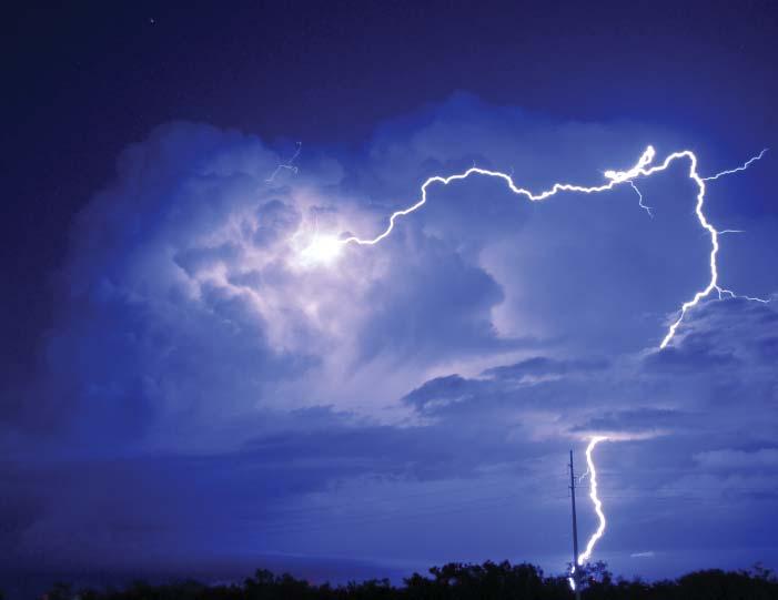
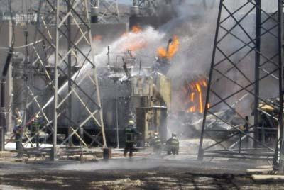
Someexamplesofsystemeventsthatcauseabnormalconditionsareasfollows:lightningstrikes (Figure1.2),wind,icestorms,animalcontact,equipmentfailures(Figure1.3),caraccidentsknockingdownelectricalpoles/equipment,etc.,thatcauseshortcircuitsorbrokenconnections.Such eventsarealsoreferredintheindustry,asfaults.Faultsandtheirtypes,causes,andhowtocalculate faultvalueswillbefurtherdiscussedinChapter6.
1.2WhyIsPowerSystemProtectionsRequired?
Powersystemsaredesigned,planned,andconstructedtolimitfailuremodesandequipmentdamageandtherebyenhanceoverallsystemreliability.
Figure1.1 Illustrationofaprotectionsystemforatransmissionline[1].
Environmentalrisklightningstrike–DallasTx.Source:NOAAPhotoLibrary/Flickr/CCBY2.0.
Figure1.3 Failedtransformeronfire–ThessalonikiGreece.Source:Konstantinos Stampoulis/Firefighters.gr/ WikimediaCommons/CCBY-SA3.0GR.
Thepowersystemisdesignedtobalanceperformanceandminimizethecostofenergydelivery. Theplanning,design,andimplementationofapowersystemisabalanceofinitialcapitalcosts andongoingmaintenancecostswiththepotentialcostimpactofpowersystemequipmentfailure. Powersystemsareexposedandsubjectedtoenvironmentalelementssuchasrain,snow,ice, lightning(Figure1.2),storms,andothersuchenvironmentalrisks.Theseriskscause,power system’sprimaryequipmentcomponentstomakeunwantedcontactwithothercomponents, referredtoasfaultswhichresultinfaultcurrentsintheorderof10–100timesnormalloadcurrents. Transmissionlineshavethehighestriskofenvironmentalelementsduetotheirincreasednatural exposuretotheenvironment.
Figure1.2