Arc Welding Processes Handbook
Ramesh Singh
This edition first published 2021 by John Wiley & Sons, Inc., 111 River Street, Hoboken, NJ 07030, USA and Scrivener Publishing LLC, 100 Cummings Center, Suite 541J, Beverly, MA 01915, USA
© 2021 Scrivener Publishing LLC
For more information about Scrivener publications please visit www.scrivenerpublishing.com.
All rights reserved. No part of this publication may be reproduced, stored in a retrieval system, or transmitted, in any form or by any means, electronic, mechanical, photocopying, recording, or otherwise, except as permitted by law. Advice on how to obtain permission to reuse material from this title is available at http://www.wiley.com/go/permissions.
Wiley Global Headquarters
111 River Street, Hoboken, NJ 07030, USA
For details of our global editorial offices, customer services, and more information about Wiley products visit us at www. wiley.com.
Limit of Liability/Disclaimer of Warranty
While the publisher and authors have used their best efforts in preparing this work, they make no representations or warranties with respect to the accuracy or completeness of the contents of this work and specifically disclaim all warranties, including without limitation any implied warranties of merchant-ability or fitness for a particular purpose. No warranty may be created or extended by sales representatives, written sales materials, or promotional statements for this work. The fact that an organization, website, or product is referred to in this work as a citation and/or potential source of further information does not mean that the publisher and authors endorse the information or services the organization, website, or product may provide or recommendations it may make. This work is sold with the understanding that the publisher is not engaged in rendering professional services. The advice and strategies contained herein may not be suitable for your situation. You should consult with a specialist where appropriate. Neither the publisher nor authors shall be liable for any loss of profit or any other commercial damages, including but not limited to special, incidental, consequential, or other damages. Further, readers should be aware that websites listed in this work may have changed or disappeared between when this work was written and when it is read.
Library of Congress Cataloging-in-Publication Data
ISBN 978-1-119-81905-9
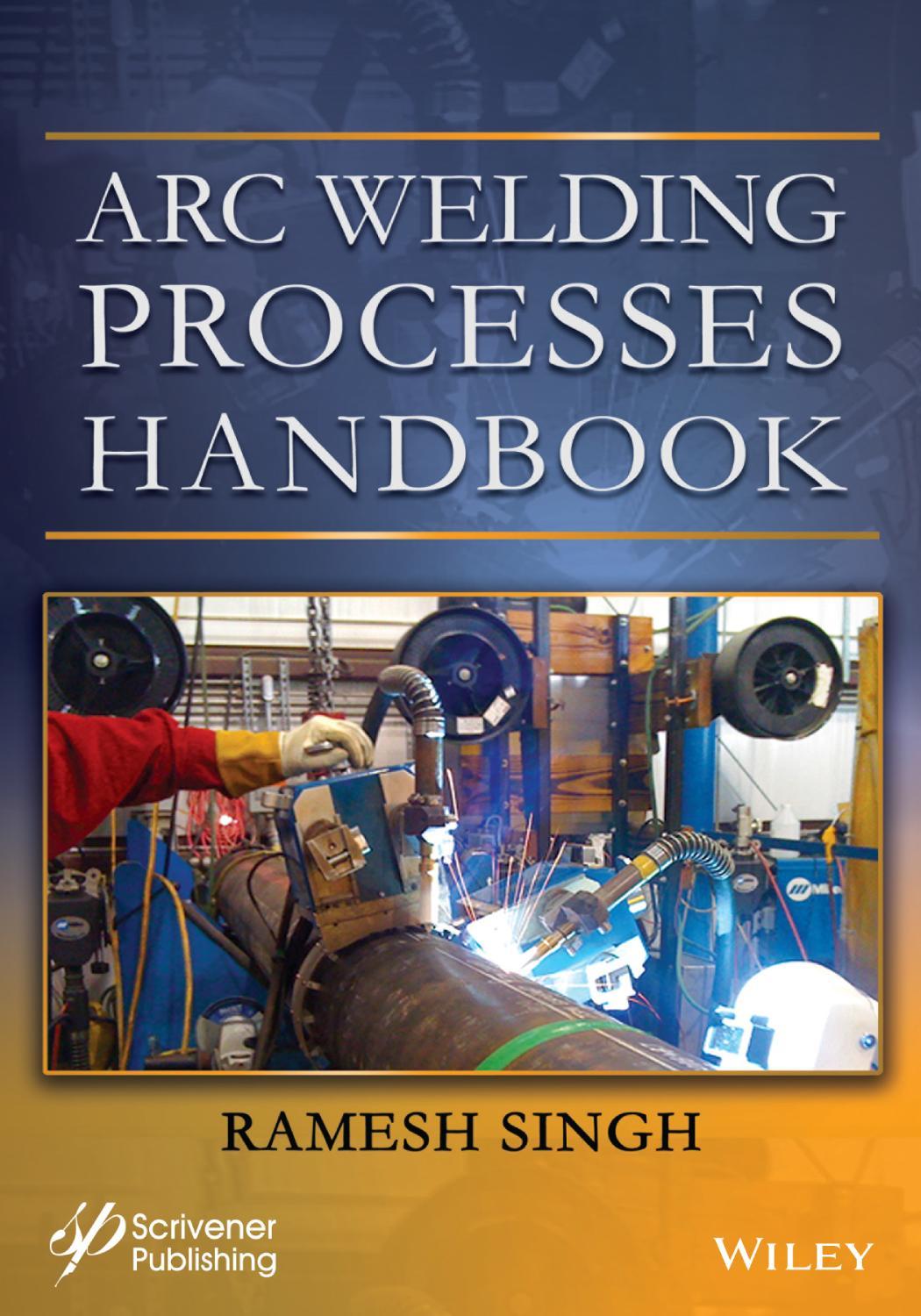
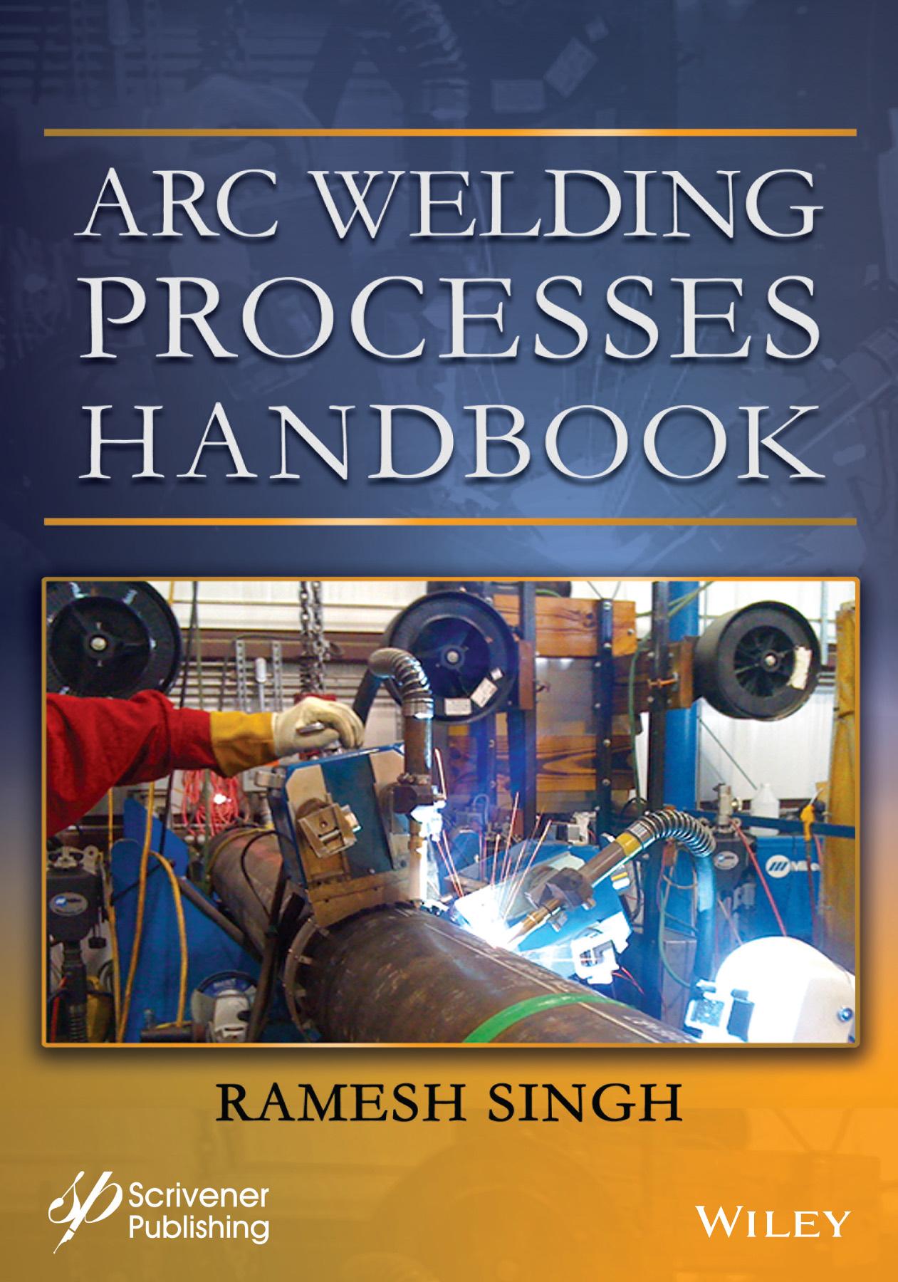
Cover image: Double headed GMAW system provided by the author
Cover design by Russell Richardson
Set in size of 11pt and Minion Pro by Manila Typesetting Company, Makati, Philippines
the USA
2.12.6
2.12.21
2.14
2.14.1
2.12.21.1
2.15.4
2.16
3.7.2.3
3.21
3.25.4
3.25.5
3.25.6
3.25.7
3.25.10.1
3.25.10.2
3.25.10.3
3.25.14
3.25.13.1
3.25.14.1
4.6
4.5.2
4.5.3
4.5.4
4.6.2.1
4.6.3
4.13.3.5 5xxx Series Alloys
4.13.3.6 6XXX Series Alloys
4.13.3.7 7XXX Series Alloys
4.13.4 The Aluminum Alloy Temper and Designation System
4.13.5 Wrought
4.13.6
4.13.7
4.13.8
4.13.8.1
4.13.9 Welding
4.13.10
4.13.11.1 The Elements that Promote Ferrite are
4.13.11.2 The Elements that Promote Austenite are
4.13.11.3
4.13.12 Weldability
4.13.12.1
4.13.12.2
4.13.12.3
4.13.12.4 Intergranular Corrosion in the Heat Affected Zone Control of Carbide Precipitation
4.13.12.5
4.13.12.16
4.13.12.17
5.3
5.4
5.5
5.4.1
5.4.2
5.5.5
5.5.6
5.5.7
5.5.8
5.5.9
5.6
5.7
5.7.2
5.8.1
5.8.2
5.8.3
5.8.4
5.8.5
5.8.6
5.8.7
5.8.7.1
5.9
5.9.1
5.9.2
5.9.3
5.9.3.3
5.9.3.4
5.10
5.9.4
5.9.5
6.4
6.5
6.6
6.5.1
6.6.1
6.7.1
7.1
7.3
6.10.2
6.10.3
6.10.4
6.10.5
6.10.6
6.10.7
7.4
7.7
7.8
7.9
Figure 2.6 Above (2 graphs), graph 1 above, shows the volt-ampere curve, (output curve or slope) at lower stings. Graph 2 below, shows the volt-ampere curve, (output curve or slope) the steep slope of a “Drooper” type of constant current arc welder
Figure 2.7
schematic above shows the key components of an AC transformer
Figure 2.7.4 A schematic of a movable coil reactor, the position of the reactor coil causes the inductive reactance of the secondary output coil resulting in the variance in current output 21
Figure 2.7.5 A magnetic amplifier transformer output control, the diode allows the current to flow in one direction, and this allows a remote control operation possible
Figure 2.7.6 The top portion of the figure shows the use of diodes – shown in Red color, and it compare it with Silicon controlled rectifiers (SCRs)
Figure 2.7.7 A schematic drawing of single-phase DC power source with SCR bridge control
Figure 2.8.1 Shows the schematic of single phase bridge type rectifier
Figure 2.8.2 Three phase bridge-type rectifier
Figure 2.8.1.1 Schematic diagram of a DC generator
Figure 2.8.1.2 Circuitry of an exciter system
Figure 2.8.3 Current conversion and resulting wave forms
Figure 2.8.3.1 Copper and aluminum welding leads: note the number of fine wires that compose a cable, and the rubber sheathing that covers them
Figure
Figure 2.11.4
Welding positions for welding a plate, the positions are primarily designated in relation to the position of the weld to the horizontal
Figure 2.11.3.5 A single pass fillet weld with (arc termination) stop in the middle and restarted (arc re-initiation) from that point
Figure 2.11.3.6 A multi-passes fillet weld-note the termination of arc start and stops are
Figure 2.11.3.7 A micro-etch of a double sided two pass fillet weld – compare the weld with the nomenclatures figure given above, to see how these two welds meet the standard requirements
Figure 2.11.4.1
Figure
Figure 2.11.5.1 Offsetting the weld setup for distortion control
Figure 2.11.9 This is a rotator with one end of the pipe held in a three-jaw, self-centering chuck the free end of the pipe rests on a free rotating roller, it can be raised or lowered to level the pipe to align the weld ends
Figure 2.11.10 This rotator is similar to the one above except that the pipe end is placed on a motor driven set of rollers on one end, and the other end is on the set of idle rollers, which can be lowered or raised to align and level the weld joint
Figure 2.11.11 A heavy-duty rotator
Figure 2.11.12 Weld tacks bridging two pieces of pipe
Figure 2.11.13 Shows a removable tack
Figure 2.11.14 This picture shows both the bridge tack using external pieces of metal below, and just above that is the tack within the groove using welding
Figure
Figure
Figure 2.11.11.3 The sketch above shows a typical weld layers of several passes –note the sequencing numbers on each pass
Figure 214.1 Nickel is in 10th group and 4th period in the periodic table, its atomic number is
Figure
Figure
Figure 3.3.2 A GTAW welder, note the welding torch, and the filler wire in each hand
Figure 3.4.1 Typical GTAW welding process with details of the welding torch
Figure 3.5.1 A typical GTAW set-up with positions of gas cylinder, welding machine, electrode holder and work-piece
Figure
Figure 3.5.3
Figure
Figure
Figure
Figure 3.7.2.3
Figure
Figure
Figure
Figure 3.9.1 Gas flow meters (A) shows the tube type flow meter, and the bottom (B) has a gauge type flow meter both calibrated in L/min
Figure
Figure
Figure 3.10.4 An assortment of manual welding GTAW torch components
Figure 3.11.2.1 The tip angle 60o, note the depth of the deeper penetration and the shape and depth of the HAZ
Figure 3.11.2.2 The tip angle 30o, note the depth of the shallower penetration and the shape of the HAZ
Figure 3.11.2.3 The tip angle 15o, note the depth of the shallowest penetration and the shape of the HAZ 149
Figure 3.12.1 Five basic weld designs, (Courtesy of Indian Air force training manual “Basic Welding Technology”) 150
Figure 3.16.1 Copper and Aluminum welding leads: note the number of fine wires that compose a cable, and the rubber sheathing that covers them 152
Figure 3.16.2 Various types of cable connectors, and ground clamp. Pictures Curtsy of LENCO catalogue 153
Figure 3.25.9.3.1 Welder is tacking a pipe prior to welding 184
Figure 3.25.9.3.2 A nozzle is welded on a pipe header
Figure 3.25.10.2.1 Schaeffler diagram
Figure 3.25.10.2 DeLong diagram
Figure 4.3.1 Typical GMAW welding
Figure 4.4.1 A GMAW operator welding on an offshore pipeline
Figure 4.4.1.1 Short circuit transfer (arc-action and cycle)
Figure
Figure 4.11.1 Typical GMAW (MIG) welding set up with the external wire feed unit
Figure 4.12.1 A typical GMAW torch with trigger type on-off switch on the handle 255
Figure 4.12.2 Blow out of the GMAW torch that shows some of the components that make up a welding torch 255
Figure 4.12.3 The GMAW torch and the cable connector 256
Figure 4.12.1.4 Copper and aluminum welding leads: note the number of fine wires that compose a cable, and the rubber sheathing that covers them
Figure 4.13.8.1 (a) Contour of a weld bead in the flat position with the work horizontal; (b) welding slightly uphill; (c) welding slightly downhill
Figure 4.13.12.1 WRC diagram
Figure 5.3.1 FCAW-S self-shielding tubular wire process
Figure 5.3.2 FCAW-G, gas shielding solid wire process
Figure 5.4.1 Typical
Figure 5.5.1 FCAW electrode classification system
Figure 5.8.7.2.1 Shows the metal transfer through the arc with CO2 shielding on the left, and 75% Ar. + CO2 on the right 320
Figure 6.3.1 Schematic display of the SAW process 330
Figure 6.3.2 Shows the submerged arc welding of a plate 331
Figure 6.3.3 Shows the SAW of a pipe in a fabrication shop – note the arc and flux position as the pipe rotates 331
Figure 6.3.4 Shows the completed pipe weld
Figure 6.3.5 Higher deposition rate of SAW process
Figure 6.6.1 Showing SAW process in progress on a pipe weld
Figure 6.6.2 Shows the collected flus for cleaning and reusing
Figure 6.7.1 Multi-wire SAW system
Figure 6.7.3 Tandem head strip wire SAW process for cladding
Figure 7.1 Structure of the welding symbol 350
Figure 7.2 Welding symbol arrows
Figure 7.3 Welding symbol position of the arrows
Figure 7.4 Significance of the circle on the arrows
Figure 7.5 Symbols for type of welds
Figure 7.6 Symbol of a fillet weld
Figure 7.7 Shows the side of the metal where the fillet weld is required to be made
Figure 7.8 Graphic and as built depiction of welds – note the weld sizes shown in the symbol on left and its corresponding annotation on the actual weld
Figure 7.9 Shows the addition of the length of the weld to the symbol at the left, and what it means is shown in the as built figure on the right 352
Figure 7.10 Adding pitch of the weld
Figure 7.11 Symbols of various types of Groove Welds 353
Figure 7.12 Symbol of Sq. groove weld – note the annotation of root opening
Figure 7.13 Symbol and as built of V-groove welds, note how the root gap (opening) is shown 354
Figure 7.14 Shows the (1) depth of V groove on both sides of the weld, (2) shows the depth of the penetration desired of the weld
Figure 7.15 Shows the specific depth of the groove weld (effective throat) desired
Figure 7.16 Symbol of a bevel groove note which side of the plate is to be beveled and to what degree
Figure 7.17 Shows U-groove symbol
Figure 7.18 Shows the J-groove symbol and the weld. Note the indicated depth of the weld
Figure 7.19 Symbol of Flare-V groove weld and as built weld
Figure 7.20 Symbol of and as built flare bevel and the weld
Figure 7.21 Shows the melt-thru weld
Figure 7.22 Shows the supplementary symbol of backing bar for the weld
Figure 7.23 Symbol of a plug weld
Figure 7.24 Shows symbols of plug and slot welds, with weld sizes, spacing and depth of the weld
Table 3.11.3
Table 3.16.1
Table 3.17.1
Table 3.21.1
Table 3.22.1
Table 3.24.1
Table 3.24.2
Table 3.25.1
Table
Table
Table
Table
Table
Table
Table
Table
Table
Table
Table
Table
Table
Table 7.7
Foreword
The book, “Arc Welding Processes Handbook”, brings together salient knowledge of arc welding methods used primarily in the industry and especially in the oil patch. The information presented about the welding process is usable and emulates the presence of your own welding engineer. Covering such welding methods as SMAW, GTAW, GMAW, FCAW and SAW with details in materials and techniques. This book is useful to both new welders as well as experienced welders. In the book, Ramesh covers these welding processes, how they work, and dives into the electrical side of welding. Welding machines, Transformers, Generators, Invertors, AC, DC, Sq. wave, Sine wave currents, Rectifiers, SCRs, Diodes, etc., as current control methods, all these are presented in a way that is easy to understand the functions of various welding machines. Most common weldable materials are discussed with welding guidance given that includes Aluminum, Nickel, Carbon steels, Stainless steels, Precipitation Hardened steels, Duplex Stainless steels, and others. The book is super comprehensive, easy to follow, and a welcome addition to any welding engineer’s bookcase. It is a truly great guide for any budding engineer or welder to help them master their skills.
David Ammerman
Project Director at Gulf Interstate Engineering, MME, Texas PE 30+ years past-member of ASME, and member of API Committee: Pipeline Construction Voting Group
Preface
The book Arc Welding Processes Handbook has been developed to address the need of a vast majority of people who want to know about welding, some of them also want to weld as hobbyists, or carry their passion for welding to be a professional welder. The book can also be used as a reference by field engineers and managers responsible for welding and fabrication activities. The book uses several figures and illustration that are available in the public domain, yet wherever it could be identified, the credit has been assigned to the source.
The book will provide readers and practitioners of the profession with an understanding of nearly all aspects of arc welding. The book covers the theory, the principles of the processes, the equipment, and the techniques that would improve the competency in welding, for each welding process. A good number of tables and illustrations are included to accentuate the points as well as to give readers familiarity with things that may or may not be available in their work or school trade workshops.
Chapter 1 introduces the reader to all possible welding process, including arc welding, electric resistance welding etc.
The practice welding procedure (WPS) given especially in Chapter 2 on SMAW process should prove a good basis to start welding and develop into an experienced welder. From here, one can move forward with other processes using the practice welding procedures included in Chapter 3 on GTAW, as well as GMAW processes in Chapter 4. For those who want to start welding, they can start with settings in these procedures and preparations and make changes to develop their skills around them. But it is not necessary to strictly follow this sequence, if someone has already developed the skills in any other process and wants to move to any other process.
The skills required to master FCAW process in Chapter 5 almost mimics the basic skills of GMAW in Chapter 4, and once this process is mastered, moving forward with the FCAW process should not be difficult at all.
The process of SAW in Chapter 6 is very different and very few welding schools will have this process in house. For students to practice on it, in most cases it will have to be learned and mastered on the job. But the chapter on SAW process gives the reader abundant information and familiarity with the process that they can step up to the opportunity when it becomes available.
Included in Chapter 7 is the welding symbols and how to use them, to read those symbols on fabrication drawings and weld accordingly. Reading and understanding the language of welding is an important step in becoming a successful welding professional. The chapter also includes other miscellaneous but important information that would come handy to any welding professional. The most important information is the detailed description of welding symbols and how to use and read them.
This book is best used in a workshop where the reader can pick up the welding torch or holder and try to convert the words from the book to an actual weld.
Singh Katy, TX June 2021
Ramesh
