RFandMicrowaveCircuitDesign
TheoryandApplications
CharlesE.Free UK
ColinS.Aitchison UK
Thiseditionfirstpublished2022 ©2022JohnWiley&SonsLtd
Allrightsreserved.Nopartofthispublicationmaybereproduced,storedinaretrievalsystem,ortransmitted,inanyformorbyanymeans, electronic,mechanical,photocopying,recordingorotherwise,exceptaspermittedbylaw.Adviceonhowtoobtainpermissiontoreusematerial fromthistitleisavailableathttp://www.wiley.com/go/permissions.
TherightofCharlesE.FreeandColinS.Aitchisontobeidentifiedastheauthorsofthisworkhasbeenassertedinaccordancewithlaw.
RegisteredOffices
JohnWiley&Sons,Inc.,111RiverStreet,Hoboken,NJ07030,USA JohnWiley&SonsLtd,TheAtrium,SouthernGate,Chichester,WestSussex,PO198SQ,UK
EditorialOffice
TheAtrium,SouthernGate,Chichester,WestSussex,PO198SQ,UK
Fordetailsofourglobaleditorialoffices,customerservices,andmoreinformationaboutWileyproductsvisitusatwww.wiley.com.
Wileyalsopublishesitsbooksinavarietyofelectronicformatsandbyprint-on-demand.Somecontentthatappearsinstandardprintversionsof thisbookmaynotbeavailableinotherformats.
LimitofLiability/DisclaimerofWarranty
Whilethepublisherandauthorshaveusedtheirbesteffortsinpreparingthiswork,theymakenorepresentationsorwarrantieswithrespectto theaccuracyorcompletenessofthecontentsofthisworkandspecificallydisclaimallwarranties,includingwithoutlimitationanyimplied warrantiesofmerchantabilityorfitnessforaparticularpurpose.Nowarrantymaybecreatedorextendedbysalesrepresentatives,writtensales materialsorpromotionalstatementsforthiswork.Thefactthatanorganization,website,orproductisreferredtointhisworkasacitation and/orpotentialsourceoffurtherinformationdoesnotmeanthatthepublisherandauthorsendorsetheinformationorservicesthe organization,website,orproductmayprovideorrecommendationsitmaymake.Thisworkissoldwiththeunderstandingthatthepublisheris notengagedinrenderingprofessionalservices.Theadviceandstrategiescontainedhereinmaynotbesuitableforyoursituation.Youshould consultwithaspecialistwhereappropriate.Further,readersshouldbeawarethatwebsiteslistedinthisworkmayhavechangedordisappeared betweenwhenthisworkwaswrittenandwhenitisread.Neitherthepublishernorauthorsshallbeliableforanylossofprofitoranyother commercialdamages,includingbutnotlimitedtospecial,incidental,consequential,orotherdamages.
LibraryofCongressCataloging-in-PublicationData
Names:Free,CharlesE.,author.|Aitchison,ColinS.,author.
Title:RFandmicrowavecircuitdesign:theoryandapplications/Charles E.Free,UK,ColinS.Aitchison,UK.
Description:Hoboken,NJ,USA:Wiley,2022.|Series:Microwaveand wirelesstechnologiesseries|Includesbibliographicalreferencesand index.
Identifiers:LCCN2020028781(print)|LCCN2020028782(ebook)|ISBN 9781119114635(hardback)|ISBN9781119114673(adobepdf)|ISBN 9781119114666(epub)
Subjects:LCSH:Radiocircuits–Designandconstruction.|Microwave circuits–Designandconstruction.
Classification:LCCTK6560.F682022(print)|LCCTK6560(ebook)|DDC 621.3841/2–dc23
LCrecordavailableathttps://lccn.loc.gov/2020028781
LCebookrecordavailableathttps://lccn.loc.gov/2020028782
CoverDesign:Wiley
CoverImages:Circuitboardbackground©Berkah/GettyImages,InsetsketchbyCharlesFree Setin9.5/12.5ptSTIXTwoTextbyStraive,Chennai,India 10987654321
1.11.1MatchingaComplexLoadImpedancetoaRealSourceImpedance
1.11.2MatchingaComplexLoadImpedancetoaComplexSourceImpedance
1.B.1StructureofCoplanarWaveguide(CPW)
1.B.2ElectromagneticFieldDistributiononaCPWLine
1.B.3EssentialPropertiesofCoplanar(CPW)Lines
1.B.4SummaryofKeyPointsRelatingtoCPWLines
1.C.1WaveguidePrinciples
1.C.5PhaseandGroupVelocities
1.C.6FieldTheoryAnalysisofRectangularWaveguides
1.C.7WaveguideImpedance
1.C.8Higher-OrderRectangularWaveguideModes
1.C.9WaveguideAttenuation
2PlanarCircuitDesignI
2.2ElectromagneticFieldDistributionAcrossaMicrostripLine
2.3EffectiveRelativePermittivity,
2.8MicrostripCoupled-LineStructures
2.8.1AnalysisofMicrostripCoupledLines
2.8.2.1DesignofMicrostripDirectionalCouplers
2.8.3ExamplesofOtherCommonMicrostripCoupled-LineStructures
2.8.3.1MicrostripDCBreak
2.8.3.2Edge-CoupledMicrostripBand-PassFilter
3.4.1EtchedCircuits
3.4.2Thick-FilmCircuits(DirectScreenPrinted)
3.4.3ThickFilmCircuits(UsingPhotoimageableMaterials)
3.4.4Low-TemperatureCo-FiredCeramicCircuits
3.5UseofInkJetTechnology
3.6CharacterizationofMaterialsforRFandMicrowaveCircuits
3.6.1MeasurementofDielectricLossandDielectricConstant
3.6.1.1CavityResonators
3.6.1.2DielectricCharacterizationbyCavityPerturbation
3.6.1.3UseoftheSplitPostDielectricResonator(SPDR)
3.6.1.4OpenResonator
3.6.1.5Free-SpaceTransmissionMeasurements
3.6.2MeasurementofPlanarLineProperties
3.6.2.1TheMicrostripResonantRing
3.6.3PhysicalPropertiesofMicrostripLines
3.7SupplementaryProblems
4PlanarCircuitDesignII
4.1Introduction
4.2DiscontinuitiesinMicrostrip
4.2.1Open-EndEffect
4.2.2Step-Width
4.2.3Corners
4.3MicrostripEnclosures
4.4PackagedLumped-ElementPassiveComponents
4.4.1TypicalPackagesforRFPassiveComponents
4.4.2Lumped-ElementResistors
4.4.3Lumped-ElementCapacitors
4.4.4Lumped-ElementInductors
4.5MiniaturePlanarComponents
4.5.1SpiralInductors
4.5.2LoopInductors
4.5.3InterdigitatedCapacitors
4.5.4Metal–Insulator–MetalCapacitor
5
5.5ReflectionCoefficientofaTwo-PortNetwork
5.6PowerGainsofTwo-PortNetworks
5.7Stability
5.A.1TransmissionParameters(ABCD Parameters)
5.A.2AdmittanceParameters(Y -Parameters)
6.2.4FaradayRotation
6.3FerritesinMetallicWaveguide
6.3.1ResonanceIsolator
6.4FerritesinPlanarCircuits
6.4.1PlanarCirculators
6.4.2Edge-Guided-ModePropagation
6.4.3Edge-Guided-ModeIsolator
6.4.4PhaseShifters
6.5Self-BiasedFerrites
6.6SupplementaryProblems
7Measurements
7.3MicrowaveVectorNetworkAnalyzers
7.3.1DescriptionandConfiguration
7.3.2ErrorModelsRepresentingaVNA
7.3.3CalibrationofaVNA
7.4On-WaferMeasurements
8RFFilters
8.4DesignStrategyforRFandMicrowaveFilters
8.5Multi-ElementLow-PassFilter
8.6PracticalFilterResponses
8.7Butterworth(orMaximallyFlat)Response
8.8Chebyshev(EqualRipple)Response
8.9MicrostripLow-PassFilter,UsingSteppedImpedances
8.10MicrostripLow-PassFilter,UsingStubs
8.11MicrostripEdge-CoupledBand-PassFilters
8.12MicrostripEnd-CoupledBand-PassFilters
8.13PracticalPointsAssociatedwithFilterDesign
8.15SupplementaryProblems
9MicrowaveSmall-SignalAmplifiers
9.3Distributed(Microstrip)MatchingNetworks
9.4DCBiasingCircuits
12.4.1BasicPrinciples
12.4.2GainofaHertzianDipole
12.5RadiationfromaHalf-WaveDipole
13.2.1.2PowerAddedEfficiency
13.2.1.3InputandOutputImpedances
Preface
Inrecentyears,therapidexpansionofcommunicationapplicationsatRFandmicrowavefrequencieshascreatedsignificant interestinthisareaofhigh-frequencyelectronics,bothinindustryandacademia.Thistextbookprovidesarigorousintroductiontothetheoryofmodern-daycircuitsanddevicesatRFandmicrowavefrequencies,withanemphasisoncurrent practicaldesign.
Oneofthethemesofthebookisthatofthedesignofhigh-frequencyhybridintegratedcircuitsinwhichindividualpassive andactivecomponentsareinterconnectedwithinaplanarcircuitstructure.Thetraditionalmethodofmakingsuchcircuits istoassemblethecomponentsonalow-losscopper-cladprintedcircuitboard,whichhasbeenetchedwiththerequired interconnectionpattern.Inrecentyears,thedevelopmentofnewmaterialsandnewfabricationtechniqueshascreated greaterscopeforthecircuitdesigner,withtheopportunitytousehybridcircuitstructuresatmuchhigherfrequencies,well intothemillimetre-waveregion.Inparticular,theuseofaphotoimageablethick-filmandlow-temperatureco-firedceramic (LTCC)materialshasenabledlow-cost,high-performancemultilayerstructurestobefabricated.Thepropertiesofthese materials,andtheirapplicationtoRFandmicrowavecircuits,arediscussedinthebook.
ThebookhasbeenorganizedtoprovideacohesiveintroductiontoRFandmicrowavetechnologyatundergraduate andMaster’sdegreelevel.Itassumesonlyabasicknowledgeofelectronicsonthepartofthereader,withthebulkofthe high-frequencymaterialbeingdevelopedfromfirstprinciples.Manyworkedexampleshavebeenincludedinthetextto emphasizethekeypoints,andsupplementaryproblemswithanswersareprovidedattheendofmostchapters.
ThematerialpresentedinthebookisbasedlargelyoncoursesinRFandmicrowavecommunicationstaughtbyboth authorsatseveralUKUniversities.
Chapter1 introducesthetheoryofRFandmicrowavetransmissionlines,whicharefundamentaltohighfrequencycircuits.ThebasictheoryisexpandedtoincludetheprinciplesandapplicationsoftheSmithchart,whichisa graphicaltoolthatcanbeusedtorepresentandsolvetransmissionlineproblems.Thischapterincludessummariesofthe propertiesofsomecommonhigh-frequencytransmissionlines,namelycoaxialcable,microstrip,coplanarwaveguide,and hollowmetallicwaveguide.
Chapter2 expandsonthetheoryandapplicationsofmicrostrip,whichwasintroducedinthefirstchapter.Microstripis byfarthemostcommontypeofinterconnectionusedforRFandmicrowaveapplications,andthechapterdiscussesthe propertiesofthistransmissionmedium,andintroducessometypicalpassivemicrostripcomponents.
Chapter3 presentsinformationonmoderncircuitmaterialsandtheassociatedfabricationtechniques.Thisisanimportantchapterinthatgoodelectricaldesignofplanarcircuitsathighfrequenciesrequiresagoodunderstandingofthe propertiesandcapabilitiesofthecircuitmaterials.Inadditiontothetraditionaletchedcircuittechniques,thechapterdiscussesnewerfabricationapproachesusingphotoimageablethick-film,LTCC,andinkjetprinting.Thechapterconcludes withadiscussionofthevariousmethodsavailableforcharacterizingcircuitmaterialsathighfrequencies.
Chapter4 continuesthethemeofplanarcircuitdesignthroughadiscussionofthediscontinuitiesassociatedwith microstripcomponents.Alsointhischapteraretheequivalentcircuitsofpackagedlumped-elementpassivecomponents, aswellasminiatureplanarcomponentsthatcanbeusedinsinglelayerandmultilayerformats.
Chapter5 introducestheconceptof S-parameters.ThesearenetworkparametersusedtocharacterizeRFandmicrowave devices,andanunderstandingoftheirmeaningandusageisessentialformicrowavedesign.Thechapterincludesinformationonpowergaindefinitions,andtheuseofflowgraphsinhigh-frequencynetworkanalysis.
Chapter6 presentsinformationonmicrowaveferrites.Ferritematerialshaveawell-establishedplaceinmicrowave technology,primarilyforprovidingnon-reciprocalcomponents.Thepropertiesofferritematerials,aswellastheirusein traditionalmetallicwaveguidecomponents,areexplained.Morerecentusesofferritematerialinmultilayerplanarcircuits arealsodiscussed.
Chapter7 isconcernedwithmeasurementsatRFandmicrowavefrequencies.Thechapterfocusesinparticularontheuse ofthevectornetworkanalyzer(VNA),whichisthemainitemoftestinstrumentationinallhigh-frequencylaboratories. AswellasdescribingthefunctionsanduseoftheVNA,thechapteraddressestheimportantissuesofcalibrationand measurementerrors.
Chapter8 providesanintroductiontoRFfilters,whichareessentialcircuitsinmosthigh-frequencysub-systems.This chaptercommenceswithareviewoftheprincipalfilterresponses,andthenextendsthetheoreticaldiscussionintopractical designdetail.Anumberofworkedexamplesofthedesignofmicrostripfiltershavebeenincluded,andthechapterends withabriefreviewoftheadvantagesofmultilayerformatsforproducinghigh-performancefiltersatRFandmicrowave frequencies.
Chapter9 presentsinformationonthedesignofhybridmicrowaveamplifiersinwhichapackagedtransistor,usuallya metalsemiconductorfieldeffecttransistor(MESFET),ispositionedbetweeninputandoutputmatchingnetworks.The chapterfocusesonthedesignofthematchingnetworks,andconsiderstheeffectsofthesenetworksontransducergain, noise,andstability.Workedexamplesareincludedtoshowthedesignstrategiesemployedformicrostripimplementation.
Chapter10 introducesthefunctionanddesignofswitchesandphaseshiftersinplanarcircuits.Thefunctionsoffour devicescommonlyusedasswitchesinRFandmicrowavecircuitsaredescribed,namelyPINdiodes,fieldeffecttransistors(FETs),microelectromechanicalswitches(MEMS),andinlinephasechangeswitches(IPCS).Theuseoftheseswitches invarioustypesofphaseshiftersaredescribed,withsupportingworkedexamplestoshowhowmicrostripphaseshifters aredesigned.
Chapter11 givesinformationonthevarioustypesofoscillatorsusedinhigh-frequencycircuits.Startingwiththecriteria foroscillationinafeedbackcircuit,thethreemaintypesoftransistoroscillatorsaredescribed,namelytheColpitts,Hartley, andClapp–Gourietoscillators.Leadingonfromthebasicoscillatorstheconceptofthevoltage-controlledoscillator(VCO) isintroduced.ManyRFandmicrowavereceivers,andmosttestinstrumentation,derivetherequiredfrequencyfromavery stablelow-frequencycrystaloscillator,andafrequencysynthesizer.Thechapterincludesadiscussionofcrystaloscillators, togetherwithareviewofthemaintypesoffrequencysynthesizersusingphase-lockedloops.Alsogivenaredescriptions ofseveraltypesofoscillatorsusedspecificallyatmicrowavefrequencies;theseincludethedielectricresonatoroscillator (DRO),andoscillatorsusingtheGunnandImpattprinciples.Oscillatornoiseisasignificantissueinmanysituations, particularlyforlow-noisereceivers,andthechapterconcludeswithadiscussionofoscillatornoise,togetherwithamethod formeasuringthisnoise.
Chapter12 presentsinformationonRFandmicrowaveantennas.Thechaptercommenceswithadiscussionofthetheoreticalaspectsofelectromagneticradiationfromsimplewirestructures,includingthehalf-wavedipole.Theanalysisisthen extendedtoconsiderthebehaviourofwirearrays.ThemostnotablearrayusedforRFandlowmicrowavefrequencycommunicationistheYagi–Udaarray,andthisisconsideredinsomedetail.Theshortwavelengthsassociatedwithmicrowave frequenciesoffermorescopefortheantennadesigner,andthechaptergivesdesigndetailsofmicrowaveantennasusing planarpatchstructuresandalsothoseusingradiationfromapertures.
Chapter13 providesanintroductiontopoweramplifiers,anddistributedamplifiers.Poweramplifiersarecommonlypositionedinasthelastdeviceinatransmitterbeforethesignalsaretransmitted,andconsequentlyanydistortionintroduced bythepoweramplifiercannotbecorrected.Distortionisthereforeoneofthemainthemesofthischapter.Alsodescribed inthischapteraredistributedamplifiers,whichprovideanattractivecombinationofhighavailablegainandverywide bandwidthatmicrowavefrequencies.
Chapter14 bringstogetheranumberofdevicesintroducedinearlierchapterswithadiscussionofRFandmicrowave receivers.Noiseisanimportantissueinanyreceiver,particularlywhenthereceivedsignallevelsareverylow,andthis chapterincludesadiscussionoftypicalsourcesofnoise,andhowtheyaffecttheperformanceofareceiver.
AbouttheCompanionWebsite
Thisbookisaccompaniedbyacompanionwebsite:
www.wiley.com/go/free/rfandmicrowave
Thewebsiteincludes:
• TeachingPDFSlides(bychapter)
• MicrostripDesignGraphs
RFTransmissionLines
1.1Introduction
Transmissionlines,intheformofcableandcircuitinterconnects,areessentialcomponentsinRFandmicrowavesystems. Furthermore,manydistributedplanarcomponentsrelyontransmissionlineprinciplesfortheiroperation.Thischapter willintroducetheconceptsofRFtransmissionalongguidedstructures,andprovidethefoundationsforthedevelopment ofdistributedcomponentsinsubsequentchapters.
FourofthemostcommonformsofRFandmicrowavetransmissionlineareshowninFigure1.1.
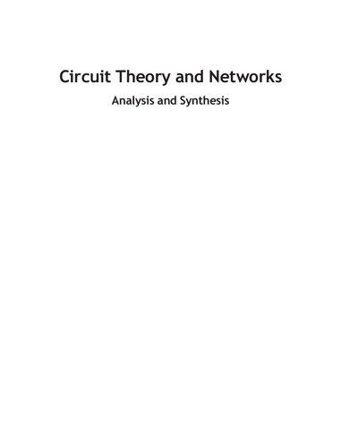
(i) Coaxialcable isanexampleofashieldedtransmissionline,inwhichthesignalconductorisatthecentreofacylindrical conductingtube,withtheinterveningspacefilledwithlosslessdielectric.Thedielectricisnormallysolid,althoughfor higher-frequencyapplicationsitisoftenintheformofdielectricvanessoastocreateasemi-air-spacedmediumwith lowertransmissionlosses.Atypicalcoaxialcableisflexiblewithanouterdiameteraround5mm,althoughmuch smallerdiametersareavailablewith1mmdiametercablebeingusedforinterconnectionswithinmillimetre-wave equipment.Also,forveryhigh-frequencyapplications,thecablemayhavearigidorsemi-rigidconstruction.Further dataoncoaxialcablesareprovidedinAppendix1.A.
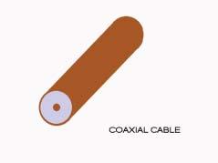
(ii) Coplanarwaveguide (CPW),inwhichalltheconductorsareonthesamesideofthesubstrate,isalsoshownin Figure1.1.Thistypeofstructureisveryconvenientforthemountingofactivecomponents,andalsoforprovidingisolationbetweensignaltracks.Coplanarlinesarewidelyusedincompactintegratedcircuitsforhigh-frequency applications.FurtherdataoncoplanarlinesaregiveninAppendix1.B.
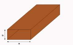
(iii) Waveguide,formedfromhollowmetaltubesofrectangularorcircularcross-section,isatraditionalformoftransmissionlineusedformicrowavefrequenciesabove1GHz.Formanycircuitandinterconnectionapplications,waveguide hasbeensupersededbyplanarstructures,anditsuseinmodernRFandmicrowavesystemsisrestrictedtoratherspecializedapplications.Itistheonlytransmissionlinethatcansupporttheveryhighpowersrequiredinsometransmitter applications.Anotheradvantageofanair-filledmetalwaveguideisthatitisaverylowlossmediumandtherefore canbeusedtomakeveryhigh-Q cavities,andthisapplicationisdiscussedinmoredetailinChapter3inrelation todielectricmeasurements.Amorerecentapplicationoftraditionalwaveguidesisinsubstrateintegratedwaveguide (SIW)structuresformillimetre-waveapplications,andthisisexplainedinmoredetailinChapter4inthecontextof emergingtechnologies.FurtherdataonthetheoryofwaveguidesaregiveninAppendix1.C.
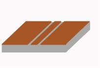
(iv) Microstrip isthemostcommonformofinterconnectionusedinplanarcircuitsforRFandmicrowaveapplications.As showninFigure1.1,itconsistsofalow-lossinsulatingsubstrate,withonesidecompletelycoveredwithaconductor toformagroundplane,andasignaltrackontheotherside.FurtherdataonmicrostriparegiveninAppendix1.D. Thisisaparticularlyimportantmediumforhigh-frequencycircuitdesignandsoChapter2isdevotedtoanin-depth discussionofmicrostripandtheassociateddesigntechniques.
1.2Voltage,Current,andImpedanceRelationshipsonaTransmissionLine
Initssimplestform,atransmissionlinecanbeviewedasatwo-conductorstructurewithagoandreturnpathforthecurrent. Forthepurposeofanalysiswemayregardanytransmissionlineasmadeupofalargenumberofveryshortlengths(�� z), eachofwhichcanberepresentedbyalumpedequivalentcircuit,asshowninFigure1.2.Intheequivalentcircuits, R and L RFandMicrowaveCircuitDesign:TheoryandApplications, FirstEdition.CharlesE.FreeandColinS.Aitchison. ©2022JohnWiley&SonsLtd.Published2022byJohnWiley&SonsLtd. Companionwebsite:www.wiley.com/go/free/rfandmicrowave
Commontypesofhigh-frequencytransmissionline.
Figure1.2 Representationofatransmissionlineintermsoflumpedcomponents.
representtheseriesresistanceandinductanceperunitlengthoftheconductors,respectively, C representsthecapacitance betweenthelinesperunitlength,and G istheparallelconductanceperunitlength,andrepresentstheveryhighresistance oftheinsulatingmediumbetweentheconductors.
Itshouldbenotedthatitislegitimatetorepresentacontinuoustransmissionlinebythelumpedequivalentcircuitshown inFigure1.2providingthat �� z issmallcomparedtoawavelength. R, L, G,and C arenormallyreferredtoastheprimary lineconstants,andhavetheunitsof Ω/m,H/m,S/m,andF/m,respectively.
Inordertoestablishrelationshipsbetweenthevoltageandcurrentonatransmissionlineweneedfirsttospecifyaline excitedbyasinusoidalvoltageatthesendingendwhoseangularfrequencyis ��.Ifwethenletthevoltageandcurrentat somearbitrarypointonthelinebe V and I ,respectively,wecanconsidertheeffectonanelementallengthatthispoint. Thevoltagedropacrosstheelementallengthwillbe �� V andtheparallelcurrentwillbe �� I ,asshowninFigure1.3.
UsingstandardACcircuittheory,wecanrelatethechangeinvoltage, �� V ,tothecomponentsoftheequivalentcircuitas
Coplanar waveguide Metal waveguide
Microstrip
Coaxial cable
Figure1.1
Figure1.3 Equivalentcircuitofanelementallength, �� z,ofatransmissionline.
Consideringtheparallelcurrent, �� I ,wehave
i.e.
DifferentiatingEq.(1.1)withrespecttotimegives
Substitutingfor dI dz fromEq.(1.2)gives
whichcanbewrittenas
where
Similarly
Todeterminethevariationof V alongtheline,wehavetosolvethedifferentialEq.(1.3)for V .Thisisasecond-order differentialequationwithastandardsolutionintheform
Thetwotermsontheright-handsideofEq.(1.6)showhowthepeakamplitudesandphasesofwavestravellinginthe forwardandreversedirectionsvarywithdistance.Thevaluesoftheamplitudesandphasesofthesewavesaredetermined bythevalueof �� ,whichisdefinedasthepropagationconstant(thisisconsideredinmoredetailinSection1.3).
DifferentiatingtheexpressioninEq.(1.6)gives
CombiningEqs.(1.7)and(1.1)gives
Rememberingthat ��
wecanrewriteEq.(1.8)as
Theimpedance, Z O ,istermedthecharacteristicimpedanceofthetransmissionline.Characteristicimpedanceisan importantpropertyofanytransmissionlineanditisusefultohaveanappreciationofitsphysicalsignificance.Theoretically, itistheratioofthevoltagetocurrentatanarbitrarypositiononaninfinitelylongtransmissionlinethatsupportsawave travellinginonedirection.Ifthelineislossless,i.e. R = 0and G = 0,thenweseefromEq.(1.10)that ZO = √L∕C andhas aconstantvaluethatisindependentoffrequency.Itfollowsthatifsuchalineisterminatedbyanimpedanceequaltothe characteristicimpedance,therewillbenoreflectionsfromthetermination.Moreover,ifatransmissionlineisterminated withitscharacteristicimpedance,thentheimpedanceattheinputofthelinewillbeequaltothecharacteristicimpedance; undertheseconditionsthelineissaidtobematched.
Consideringthesendingendoftheline,i.e. z = 0,thenfromEqs.(1.6)and(1.9)weobtain
where V S and I S arethevoltageandcurrentatthesendingendoftheline,respectively. RearrangingEq.(1.11)toobtain V 1 and V 2 gives:
Thevoltage, V ,andcurrent, I ,atanydistance, z,alongthetransmissionlinecannowbefoundintermsofthevoltage andcurrentatthesendingendbysubstituting V 1 andV2 fromEq.(1.12)intoEqs.(1.6)and(1.9)giving
Equation(1.13)maybewrittenintermsofhyperbolicfunctionsas
Similarly,
Theimpedance, Z z ,atanydistance z fromthesendingendofthelinecannowbefoundbydividingEq.(1.14)byEq.(1.15) giving
where ZS = VS IS istheimpedanceatthesendingendoftheline.
Ifwenowconsideratransmissionlineoffinitelength, l,terminatedbyanarbitraryimpedance, Z L ,then Z z = Z L when z = l,andEq.(1.16)canberewrittenas
Theinputimpedance, Z in ,ofatransmissionlineterminatedbyanimpedance, Z L ,canbefoundbyrearrangingEq.(1.17) togive
Thisisanimportant,butcomplicated,expressiongivingtheinputimpedance, Z in ,ofatransmissionlineterminatedin Z L intermsofthepropagationconstant, �� ,thecharacteristicimpedance, Z O ,andthelinelength, l.Ifthelineislowloss, Eq.(1.18)canbesignificantlysimplified,asisshownlaterinthechapter.
1.3PropagationConstant
ThepropagationconstantwasintroducedinEq.(1.4).Thisconstantdeterminestheamplitudeandphaseofawavepropagatingalongatransmissionlineataparticularfrequency,andmayconvenientlybeexpressedas
where �� istheattenuationconstantand �� isthephasepropagationconstant.Consideringthefirsttermontheright-hand sideofEq.(1.6)wehave
where V F representsthevoltageoftheforwardwaveatadistance l alongtheline.Themagnitudeofthiswaveisgivenby
Rearrangingthisequationgives
TakingthenaturallogarithmoftheratiooftwovoltagesgivestheratiointheunitsofNepers;so �� willhavetheunitsof Np/m (Nepers/metre).AlthoughNepersarenotincommonuseasaunitinRFwork,itisimportanttobeabletoconvert avoltageratiofromNepertothemoreusualpowerunitofdB.
Consideringavoltageratio, �� ,wehave
Theimaginarypartofthepropagationconstantgivesthetransmissionphasechangeexperiencedbythewaveintravelling adistance, z.Sincethereare2�� radiansinonewavelength,thephasepropagationconstantisalwaysgivenby
where �� isthewavelengthalongthelinebeingconsidered.ItfollowsfromEq.(1.25)thatthephasepropagationconstant hastheunitsof rad/m (radians/metre).
1.3.1Dispersion
Theforegoingtheorydescribesthepropagationalongatransmissionlineatasinglefrequency.Butsinceall information-carryingsignalscontainmorethanonefrequency,itisimportanttoknowhowthepropagationcharacteristics ofalinechangewithfrequency.
Ifallthefrequenciescontainedinasignaltravelatthesamevelocity,thetransmissionlineissaidtobedispersionless. Ifthisisnotso,andifthephasevelocity,1 vP ,isafunctionoffrequency,thetransmissionlinewillexhibitdispersion.If dispersionispresent,asignalcontaininganumberoffrequencycomponents,suchasavoltagepulse,willbecomedistorted asitpropagatesalongtheline,withthedegreeofdistortionincreasingwiththedistanceofpropagation.
Ausefulconceptindeterminingthedegreeofdispersionisgroupvelocity, vg .Wecanexplainthisconceptbyconsidering thetransmissionofasignalwhichconsistsofanumberofsinusoids,eachhavingadifferentfrequencyandamplitude. Thesefrequencycomponentswillcombinetoformacompositepattern,withaparticularenvelope.Thegroupvelocityis thevelocitywithwhichthisenvelopepropagatesalongthetransmissionline.Itcanbeshownthatthegroupvelocityis givenby
Ifthisvelocityisindependentoffrequency,thenthelinewillbedispersionlessandthephaserelationshipsbetweenthe frequencycomponentsofthesignalwillbemaintained.
Thereciprocalofthegroupvelocityisknownasthegroupdelay,andistheslopeofthe �� –�� responseataparticular frequency.If �� isalinearfunctionoffrequency,thenthe �� –�� responsewillbeastraightlineandthegroupdelaywillbe constant,andindependentoffrequency.Toavoiddistortionitisimportantthatthegroupdelayisconstantoverthefull frequencyrangeofthesignalbeingtransmitted.
1.3.2AmplitudeDistortion
Amplitudedistortionwilloccuriftheattentionconstant, �� ,isavaryingfunctionoffrequency,thuscausingthefrequency componentsofacomplexsignaltosufferdifferentamplitudechangesasthesignalpropagates.Fornoattenuationdistortion tooccur,werequire ���� �� f = 0.NormallyattenuationdistortionisnotsignificantforRFandmicrowavecircuitinterconnections,sincetheseinterconnectionsareshortanddeliberatelydesignedtobelowloss.
1.4LosslessTransmissionLines
ThemajorityoftransmissionlinesencounteredinRFandmicrowavecircuitsarebothshortanddeliberatelymanufactured tohavelowdissipativelosses.Consequently,itisusefultoconsiderhowtheforegoingtheoryismodifiedbyconsidering transmissionlinestobelossless.
Alosslesslinewillhave R = G = 0,andEq.(1.10)willbemodifiedsuchthatthecharacteristicimpedanceofthelineis realandgivenby
Also,sincetherearezerolossesintheline,theattenuationcoefficient, �� ,willbezeroandthepropagationcoefficientwill onlyrepresentthephasebehaviourofthewaveontheline,i.e.
1Thephasevelocityisthevelocitywithwhichphaseofasinusoidistransmitteddowntheline.Itisrepresentedby v p ,where v p = ��/�� .Phase velocityisdiscussedinmoredetailinAppendix1.C.5,inrelationtopropagationthroughwaveguides.
and
With �� = j�� ,theexpressionfortheinputimpedanceofatransmissionlineisalsomodified,andEq.(1.18)becomes
Recallingthatcosh(jx ) = cos(x )andsinh(jx ) = j sin(x ),Eq.(1.30)canberewrittenas
or
Thisisanimportantexpressiongivingtheinputimpedance, Z in ,ofaloss-freetransmissionlineterminatedin Z L interms ofthephasepropagationconstant, �� ,characteristicimpedance, Z O ,andlinelength, l
Example1.1 Thefollowinglineconstantsapplytoalosslesstransmissionlineoperatingat100MHz: L = 0.5 μH/m, C = 180pF/m.
Determine:
(i)Thecharacteristicimpedanceoftheline.
(ii)Thephasepropagationconstant.
(iii)Thevelocityofpropagationontheline.
(iv)Thephasechangeovera20cmlengthoftheline.
Solution
(i)
Example1.2 Aparticularlosslesstransmissionlinehasacharacteristicimpedanceof75 Ω,andaphaseconstant of4rad/m.Determinetheinputimpedanceofa30cmlengthofthetransmissionlinewhenitisterminatedbyan impedanceof(100 j50) Ω.
Solution
UsingEq.(1.32):
1.5MatchedandMismatchedTransmissionLines
UsingEq.(1.32),wecanestablishtheconditionsformatchingalosslesstransmissionlineofcharacteristicimpedance, Z O , terminatedinaload, Z L :
(i) Matchedline.If Z L = Z O ,then Z in = Z O andthelineisdescribedasbeingmatched,andalloftheenergytravelling fromthesendingendwillbeabsorbedbytheloadandtherewillbenoreflected(reverse)wave.
(ii) Totallymismatchedline.Iftheloadimpedanceisreplacedbyeitherashort-circuit,oranopen-circuit,thelineis describedasbeingtotallymismatchedandnoenergywillbedissipatedinthetermination.Theinputimpedanceis thenentirelyreactive.
With Z L = 0(i.e.ashort-circuit)Eq.(1.32)becomes:
With Z L =∞ (i.e.anopen-circuit)Eq.(1.32)becomes:
(iii) Partiallymismatchedline.Withanarbitraryvalueofloadimpedance,someoftheincidentenergywillbereflected fromthetermination,givingrisetoastandingwaveasdescribedinSection1.6.
1.6WavesonaTransmissionLine
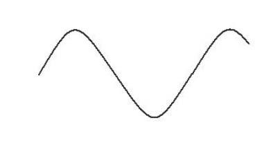
If Z L ≠ Z O ,atransmissionlinewillbemismatchedandsomeoftheenergywillbereflectedfromtheload.Underthese circumstances,theincidentandreflectedtravellingwaveswillinteracttoformaninterferencepattern.Sincetheincident andreflectedwavesmustbeatthesamefrequencyiftheloadisapassiveimpedance,theinterferencepatternwilltakethe formofastandingwave,withthemaximaandminimaofthepatterninfixedpositions.Thedistancebetweentwoadjacent maximaorminimamustbe ��/2,where �� isthewavelengthontheline.Atypicalvoltagestandingwavepatternisshown inFigure1.4.
Figure1.4 Standingvoltagewave.
Thevoltageatthemaximumpointofthepatternwillbe V max = |V F | + |V R |andattheminimumpoint V min = |V F | |V R |, where V F and V R arethepeakvoltagesoftheforwardandreflectedwaves,respectively.Thedegreeofmismatchon atransmissioncanbespecifiedbytwoparameters,namelythevoltagestandingwaveratio(VSWR)andthereflection coefficient, ��.Thesetwoparametersaredefinedasfollows. VSWRisdefinedas
Sinceweknowthat V R = 0foramatchedload,and V R = V F foratotalmismatchwherealltheenergyisreflected,we candeducetherangeofVSWRvaluesas
When Z L = Z O ,theVSWRisunity. Reflectioncoefficient, ��,isdefinedas
Itfollowsthattherangeofthemagnitudeof �� isgivenby
withzerobeingthebestvalue,andunitycorrespondingtototalreflectionfromtheload.Itshouldbenotedthat �� isacomplexquantity,givingbothmagnitudeandphaseinformation,andthisisanessentialparameterinthedesignofmatching networks,whichwillbediscussedlaterinthechapter.
Clearly,theremustbesomerelationshipbetweenVSWRandreflectioncoefficient,sincebothparametersprovideinformationaboutthedegreeofreflectionfromaload,andthisrelationshipisshowninEq.(1.39)
Also,wecandeterminearelationshipbetweenreflectioncoefficientandimpedancebyfirstrewritingEq.(1.11)inthe form
RearrangingEq.(1.41)gives
Example1.3 WhatistheVSWRcorrespondingtoareflectioncoefficientof0.4∠−22∘ ?
Solution
1.7TheSmithChart
TheSmithchart,developedbyJ.B.Smithin1935,isagraphicaltoolusedinthedesignofRFandmicrowavecircuits.Whilst atechniquethatinvolvesgraphicalmanoeuvresisliabletosignificantreadingandplottingerrors,theSmithchartisstill usefulingivingaquickvisualappreciationofacircuitproblem,whichcansubsequentlybereworkedusingCADtogive precisedesigninformation.
OneofthemainmodernapplicationsoftheSmithchartisinmeasuringinstrumentationtodisplaycircuitparametersas afunctionoffrequency,andthechartformsanessentialpartofthedisplayinmodernnetworkanalyzers(seeChapter7).
1.7.1DerivationoftheSmithChart
Equation(1.42)canbewrittenintermsofnormalizedimpedancesas
where z representsanormalizedimpedance,definedas
where Z O isthecharacteristicimpedanceoftheline.
(Itshouldbenotedthatwehaveusedthenormalconventionwhereby normalized valuesofimpedance,resistance,and reactancearerepresentedbylower-caselettersz,r,andx,respectively.)
Writing z = r + jx ,Eq.(1.43)canbeexpandedas
Sinceweknowthereflectioncoefficientisacomplexquantity,representingmagnitudeandphase,wecanwrite
CombiningEqs.(1.45)and(1.46)gives
WecansolveEq.(1.47)byequatingtherealandimaginaryparts,andaftersomelaborious,butroutinemaths,weobtain
and
ItcanbeseenthatEqs.(1.48)and(1.49)arebothintheformofequationsrepresentingcirclesinthe U V plane.
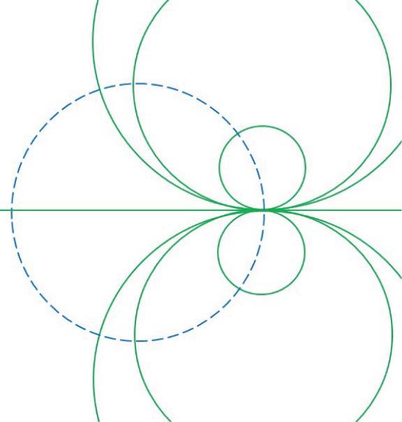
Foraparticularvalueof r ,Eq.(1.48)representsacircleofradius 1 r +1 withacentreat ( r r +1 , 0).Thevalueof r istherefore constantaroundanyparticularcircle.Thesearetermedconstantnormalizedresistancecirclesandexamplesaredrawnin Figure1.5.
Similarly,foraparticularvalueof x ,Eq.(1.49)representsacircleofradius 1 x withcentreat (1, 1 x ).Theseareconstant normalizedreactancecircles,andexamplesaredrawninFigure1.6,whereitshouldbenotedthat x cantakebothpositive andnegativevalues,sincewecanhavebothpositiveandnegativereactanceinapracticalcircuit.Itcanalsobeseenthatthe circlerepresenting x = 0hasaninfiniteradius,andisthereforerepresentedbyastraightlinecoincidentwiththe U -axis. Forreference,the r = 0circlehasalsobeenshowninFigure1.6.
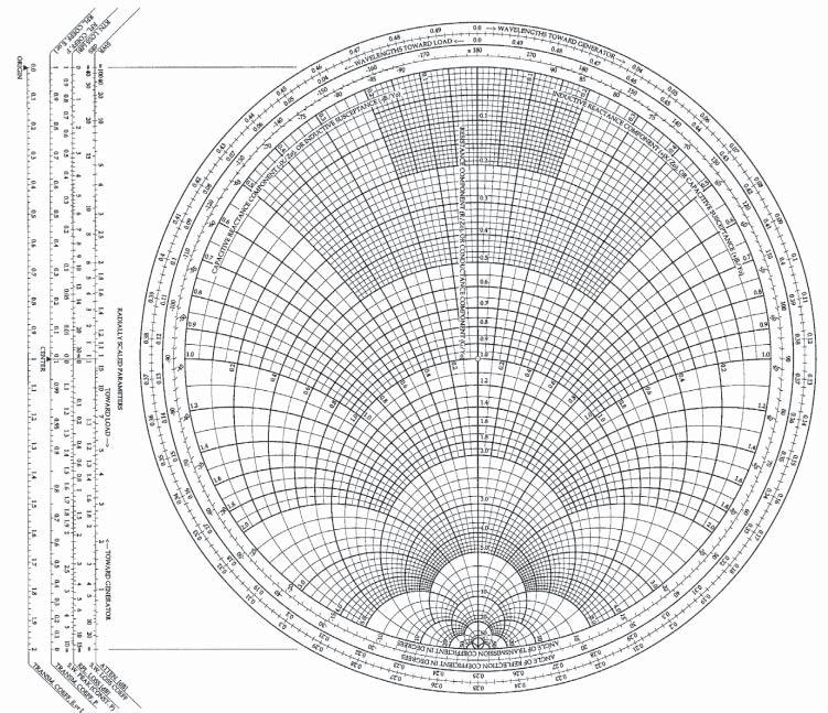
ThesetsofcirclesshowninFigures1.5and1.6canbecombinedontoasingle U V plot,andthisformstheSmith chart.AtypicalSmithchartisshowninFigure1.7.Notethatonlyreactancelinesthatliewithinthe r = 0circleareshown, sincenormalizedresistancevalueslessthanzerohavenophysicalmeaning.Notealsothattheresistanceandreactance circlesconstitutingtheSmithchartaredrawninthepolardiagramplaneofthereflectioncoefficient,andconcentriccircles, centredonthe U = 0and V = 0origin,representvaluesofconstantreflectioncoefficientamplitude.Thesecirclesarenot normallyincludedontheSmithchart,butaredrawnonbytheuser,aswillbeshowninsubsequentexamples.
Figure1.5 Normalizedconstantresistancecircles.
Figure1.6 Normalizedconstantreactancecircles.
TheSmithchartshowninFigure1.7isanexampleofacommerciallydrawnchart,anditcanbeseenthatinadditionto thenormalizedresistanceandreactancecirclesthathavebeendiscussed,asetofscaleshasbeenprovidedontheleft-hand side.Thesescalesareausefulaidforplottingradialdistancesonthechart,whichcorrespondtoparticularvaluesofVSWR andreflectioncoefficient.Theuseofthesescaleswillbedemonstratedinthesolutionsofworkedexampleslaterinthe chapter.
1.7.2PropertiesoftheSmithChart
(i)Animpedancepointisplottedonthechartbylocatingtheintersectionoftheappropriateresistanceandreactance lines,rememberingthatthechartonlydisplaysnormalizedvalues.
(ii)Sincethechartwasdrawninthereflectionplane,i.e. �� = U + jV ,pointsoncirclesthatareplottedwiththeircentreat theoriginrepresentreflectioncoefficientsofconstantmagnitude.Thesecircles,whicharenotprintedonthechartbut needtobedrawnbytheuser,areoftenreferredtoasconstantVSWRcircles(orusuallyjustasVSWRcircles).Moving aroundaconstantVSWRcirclecorrespondstomovingalongatransmissionline,therebychangingtheangleofthe reflectioncoefficient.However,thedirectionofrotationaroundaVSWRcircleisimportant,sincemovingfromthe generatorendofatransmissionlinetowardstheloadwillmaketheangleofthereflectioncoefficientmorepositive, andconverselymovingfromtheloadtowardsthegeneratorwillmaketheangleofthereflectioncoefficientmore negative.ToaidtheuseroftheSmithchart,anannularscaleshowingtheangleofthereflectioncoefficientisprinted aroundtheoutsideofthechart(theuseofthisscaleisdiscussedinpoint(iii)anddemonstratedinExample1.4).We knowfromtheearlierdiscussionofstandingwavesthatthevoltagepatternonamismatchedtransmissionlinewill repeateveryhalf-wavelength,andthereforemakingacompleterevolutionfromagivenpointonaVSWRcircle,to returntothesamepoint,mustcorrespondtomovingadistance ��/2alongtheline.Appropriatewavelengthscales areprovidedaroundtheperipheryofthechart.Notethattherearetwoscales,denotingtwodifferentdirectionsof movement.DistancesontheSmithchartarealwaysrepresentedaselectricallengths,i.e.asfractionsofawavelength. (iii)Reflectioncoefficientscanbeplotteddirectlyonthechart.Radialdistancescorrespondtothemagnitudeofthereflectioncoefficientonalinearscale,startingat0inthecentreofthechart(theorigininthe U V plane),andwitha maximumof1atthemaximumcircumference.SomemanufacturersoftheSmithchartprovideareflectioncoefficientscaleasanaidtoplotting(Figure1.7).Smithchartsalsocontaincircumferentialscalescorrespondingtothe angleofthereflectioncoefficient.Soplottingareflectioncoefficientpointinvolvesidentifyingtheradiallinethrough theappropriateangle,andthenmarkingtherequiredradialdistancealongthisline.
Figure1.7 TheSmithchart.